It is impossible to imagine the operation of any car without any devices powered by electric current. Starting from the most basic thing - supplying a spark, and ending with secondary functions that affect the comfort of the driver and passengers - heated seats, LCD monitor and audio system, GPS navigator, etc., they all require a certain amount of current to operate.
There are not so many electrical appliances in the VAZ 2108 car, but still, they need constant recharging. Where it comes from, how it gets to each device, what methods of protection it has, etc., we will look at in this article.
VAZ 2108 options
| Model | Option code | Location of controls | Execution | Engine | Injection system components and controller | Toxicity standards | Dashboard | Note |
| VAZ-2108 | 10 | left | “Norm” for the domestic market | 2108, 1.3 l, carburetor with contactless ignition system | — | R-83 | 2108 "low" | -> 01.00 |
| VAZ-21081 | 10 | left | "Standard" for the domestic market | 21081-10, 1.1 l, carburetor with contactless ignition system | — | R-83 | 2108 "low" | -> 05.97 |
| VAZ-21083 | 10 | left | “Norm” for the domestic market | 21083-50, 1.5 l, carburetor with contactless ignition system | — | R-83 | 2108 "low" | -> 09.00 |
| 10 | left | “Standard” for the domestic market “basic” | 21083-53, 1.5 l, carburetor with contactless ignition system | — | R-83 | 21083 "high" | 09.00-> | |
| 110 | left | “Norm” for the foreign market | 21083-50, 1.5 l, carburetor with contactless ignition system | — | R-83 | 2108 "low" | -> 09.00 | |
| 110 | left | “Standard” for the foreign market basic | 21083-53, 1.5 l, carburetor with contactless ignition system | — | R-83 | 21083 "high" | 09.00-> | |
| 143 | left | "Norm" for the Gulf countries | 21083-43, 1.5 l, carburetor with contactless ignition system | — | R-83 | 2108 "low" | ->09.00 with speed indicator | |
| VAZ-21083-01 | 10 | left | "Standard" for the domestic market | 21083-50, 1.5 l, carburetor with contactless ignition system | — | R-83 | 2108 "low" | -> 09.00 |
| 10 | left | “Norm” for the domestic market “basic” | 21083-53, 1.5 l, carburetor with contactless ignition system | — | R-83 | 21083 "high" | 09.00-> | |
| 110 | left | "Standard" for the foreign market | 21083-50, 1.5 l, carburetor with contactless ignition system | — | R-83 | 2108 "low" | ->09.00 | |
| 110 | left | The “norm” for the foreign market is basic | 21083-53, 1.5 l, carburetor with contactless ignition system | — | R-83 | 21083 "high" | 09.00-> | |
| 143 | left | "Standard" for the Gulf countries | 21083-43, 1.5 l, carburetor with contactless ignition system | — | R-83 | 21083 "low" | ->09.00 with speed indicator | |
| VAZ-21083-02 | 10 | left | "Lux" for the domestic market (basic) | 21083-53, 1.5 l, carburetor with contactless ignition system | — | R-83 | 21083 "high" | 09.00->;with fog lights and headlight cleaning |
| VAZ-21083-03 | 10 | left | "Lux" for the domestic market | 21083-50, 1.5 l, carburetor with contactless ignition system | — | R-83 | 21083 "high" | -> 09.00; with fog lights and headlight cleaning |
| VAZ-21083-20 | 10 | left | "Standard" for the domestic market | 2111-87, 1.5 l, with distributed fuel injection | GM, 2111-1411020-22 | R-83 | 21083 "high" | -> 03.00 |
| 10 | left | “Standard” for the domestic market (basic) | 2111-88, 1.5 l, with distributed fuel injection | Rus+B, 2111-1411020-70, 2111-1411020-71 | R-83 | 21083 "high" | 09.00->;with immobilizer | |
| VAZ-21083-21 | 10 | left | “Norm” for the domestic market (basic) | 2111-86, 1.5 l, with distributed fuel injection | Rus+B, 2111-1411020-60, 2111-1411020-61 | Euro 2 | 21083 "high" | ->03.00; with neutralizer and immobilizer |
| VAZ-21083-22 | 110 | left | for the foreign market | 2111-83, 1.5 l, with distributed fuel injection | GM, 2111-1411020-22 | Euro 2 | 2108 "low" | ->03.00; with neutralizer and immobilizer |
| 10 | left | Domestic Luxury (Basic) | 2111-86, 1.5 l, with distributed fuel injection | Rus+B, 2111-1411020-60, 2111-1411020-61 | Euro 2 | 21083 "high" | 09.00->;with neutralizer, immobilizer, fog lights and headlight cleaning | |
| VAZ-21083-23 | 10 | left | for the domestic market | 2111-82, 1.5 l, with distributed fuel injection | GM, 2111-1411020-22 | Euro 2 | 21083 "high" | ->03.00; with neutralizer and immobilizer |
| VAZ-21083-24 | 10 | left | for the domestic market | 2111-89, 1.5 l, with distributed fuel injection | Rus+B, 2111-1411020, 2111-1411020-70, 2111-1411020-71 | R-83 | 21083 "high" | with immobilizer |
| 20 | left | for the domestic market | 2111-86, 1.5 l, with distributed fuel injection | Rus+B, 2111-1411020-40 | Euro 2 | 21083 "high" | with neutralizer and immobilizer | |
| 21 | left | for domestic market | 2111-86, 1.5 l, with distributed fuel injection | Rus+B, 2111-1411020-60 2111-1411020-61 | Euro 2 | 21083 "high" | with neutralizer and immobilizer | |
| 110 | left | for the foreign market | 2111-86, 1.5 l, with distributed fuel injection | Rus+B, 2111-1411020-40 | Euro 2 | 21083 "high" | with neutralizer and immobilizer | |
| 130 | left | for the foreign market | 2111-74, 1.5 l, with distributed fuel injection | Rus+B, 2111-1411020-50 | Euro-3 | 21083 "high" | with neutralizer, immobilizer, rough road sensor and phase sensor | |
| 131 | left | for the foreign market | 2111-86, 1.5 l, with distributed fuel injection | Rus+B, 2111-1411020-40 | Euro 2 | 21083 "high" | with neutralizer, immobilizer and rear seat head restraints | |
| 138 | left | for Sweden | 2111-86, 1.5 l, with distributed fuel injection | Rus+B, 2111-1411020-40 | Euro 2 | 21083 "high" | with neutralizer, immobilizer and headlight cleaning | |
| 139 | left | for Scandinavian countries | 2111-74, 1.5 l, with distributed fuel injection | Rus+B, 2111-1411020-50 | Euro-3 | 21083 "high" | with neutralizer, immobilizer, rough road sensor and phase sensor, and headlight cleaning | |
| 143 | left | for Gulf countries | 2111-86, 1.5 l, with distributed fuel injection | Rus+B, 2111-1411020-40 | Euro 2 | 21083 "high" | with neutralizer, immobilizer, overspeed alarm | |
| 176 | left | for Israel | 2111-86, 1.5 l, with distributed fuel injection | Rus+B, 2111-1411020-40 | Euro 2 | 21083 "high" | with neutralizer, immobilizer, and tinted windows | |
| VAZ-21086 | 610 | right | Norm for the foreign market | 2108, 1.3 l, carburetor with contactless ignition system | — | R-83 | 21086 "low" | ->01.99 speedometer with combined MPH scale - km/h |
| VAZ-21087 | 610 | right | Standard for the foreign market | 21081-10, 1.1 l, carburetor with contactless ignition system | — | R-83 | 21086 "low" | ->01.99 speedometer with combined MPH scale - km/h |
| VAZ-21088 | 610 | right | Norm for the foreign market | 21083-50, 1.5 l, carburetor with contactless ignition system | — | R-83 | 21086 "low" | ->01.99 speedometer with combined MPH scale - km/h |
| VAZ-21088-01 | 610 | right | Standard for the foreign market | 21083-50, 1.5 l, carburetor with contactless ignition system | — | R-83 | 21086 "low" | ->01.99 speedometer with combined MPH scale - km/h |
| VAZ-21088-22 | 610 | right | for the foreign market | 2111-83, 1.5 l, with distributed fuel injection | GM, 2111-1411020-21 | Euro 2 | 21086 "low" | ->01.99 with neutralizer, immobilizer, speedometer with combined MPH scale - km/h |
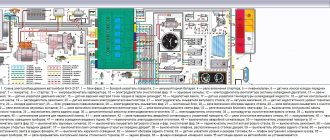
VAZ 2108 carburetor diagram
Front half of the diagram
| Position number on the diagram | Explanation of position |
| 1 | headlight |
| 2 | headlight wiper motor*; |
| 3 | engine compartment light switch |
| 4 | signaling |
| 5 | engine blower fan motor |
| 6 | fan motor connection sensor; |
| 7 | generator |
| 8 | electromagnetic throttle for connecting headlight washers |
| 9 | electromagnetic throttle for rear window washer connection* |
| 10 | solenoid valve for windshield washer connection |
| 11 | spark plugs |
| 12 | ignition distributor sensor |
| 13 | ignition salenoid VAZ 2108 |
| 14 | rear traffic light switch |
| 15 | TOZ indicator device |
| 16 | starter VAZ 2108 |
| 17 | battery |
| 18 | brake fluid level sensor |
| 19 | switch VAZ 2108 |
| 20 | TDC sensor 1st cylinder |
| 21 | diagnostic terminal block |
| 22 | ECU for carburetor electromagnetic throttle; |
| 23 | starter switch relay |
| 24 | carburetor limit switch |
| 25 | carburetor electromagnetic plunger |
| 26 | oil pressure control sensor; |
| 27 | windshield washer motor |
| 28 | electric heater fan motor |
| 29 | additional resistance of the electric motor of the interior heater |
| 30 | heater fan switch |
| 31 | electric windshield wiper motor |
| 32 | cigarette lighter |
| 33 | heater lever light bulb |
| 34 | portable light bulb socket |
* Installed on parts of manufactured cars.
Rear half of the diagram
| Position number on the diagram | Explanation of position |
| 35 | engine compartment lighting |
| 36 | glove box light bulb |
| 37 | fuse block VAZ 2108 |
| 38 | instrument lighting switch |
| 39 | handbrake control switch |
| 40 | brake light switch |
| 41 | steering column switch |
| 42 | size switch |
| 43 | hazard switch |
| 44 | rear fog light switch |
| 45 | fog light line fuse |
| 46 | rear window heating switch |
| 47 | side turn signals; |
| 48 | lamp |
| 49 | connector for connecting to an individual light fixture; |
| 50 | light button on the door pillars |
| 51 | ignition switch |
| 52 | ignition lock |
| 53 | dashboard |
| 54 | carburetor choke control switch |
| 55 | rear lights |
| 56 | meter for level indicator and fuel remaining; |
| 57 | rear window defroster |
| 58 | electric rear window wiper motor |
| 59 | room lighting fixtures |
| A | the order of conditional numbering of the terminals in the ignition switch block |
| IN | numbering order of the terminals in the windshield wiper electric motor block |
* Mounted on some passenger cars.
One-piece scheme
Healthy ! VAZ 2109 diagram.
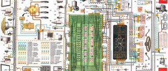
Electrical supply diagram
These are the main components of the VAZ-2104 power supply system.
Its full diagram is presented below:
| 1 | Block headlights (includes low and high beam lamps, front dimensions) | 40 | Lamp switches (in door pillars) |
| 2 | Side turn signals (located on the fenders) | 41 | Body interior lamp |
| 3 | battery | 42 | Rear window heating switch with indicator light |
| 4 | Starter relay | 43 | Handbrake control |
| 5 | Electro-pneumatic carburetor valve (idle speed) | 44 | Rear PTF activation control |
| 6 | TDC sensor of the first cylinder | 45 | Checking the brake fluid level |
| 7 | Starter | 46 | Switch for washing and cleaning the rear window |
| 8 | Carburetor microswitch | 47 | Hazard switch |
| 9 | Electric motors for headlight cleaners | 48 | Handbrake control relay breaker |
| 10 | Generator | 49 | Turn signal switch |
| 11 | Sound signals | 50 | Headlight switch |
| 12 | Candles; | 51 | Horn switch |
| 13 | Engine compartment lamp | 52 | Switch for washing and cleaning glass and headlights |
| 14 | Coolant temperature sensor | 53 | Warning lamp block |
| 15 | Oil pressure lamp sensor | 54 | Switch for washing and cleaning glass and headlights |
| 16 | Distributor-breaker | 55 | Egnition lock |
| 17 | Windshield washer motor | 56 | Instrument panel lighting switch |
| 18 | Coil | 57 | PTF switch in the rear headlights |
| 19 | Brake fluid level sensor | 58 | Coolant temperature indicator |
| 20 | Headlight washer motors | 59 | Dashboard |
| 21 | Pneumatic valve control unit | 60 | Oil pressure check |
| 22 | Diagnostic block | 61 | Gasoline level indicator with reserve control |
| 23 | Windshield wiper relay | 62 | Battery charge control |
| 24 | Turn signal and emergency flasher relay; | 63 | Voltmeter |
| 25 | Window cleaning system motor; | 64 | Speedometer |
| 26 | Socket for connecting a portable lamp; | 65 | Checking side lights |
| 27 | Brake light switch | 66 | Turn signal control |
| 28 | Engine with interior heating | 67 | High beam control |
| 29 | Heating motor resistor | 68 | Dashboard light bulb |
| 30 | Handbrake warning lamp switch | 69 | Engine switch with ventilation and heating |
| 31 | Reverse light switch | 70 | Rear window washer motor |
| 32 | Mounting block | 71 | Rear block lights |
| 33 | Low beam relay | 72 | License plate lights |
| 34 | High beam relay | 73 | Rear window heating element |
| 35 | Jumper (instead of horn relay) | 74 | Rear window wiper motor |
| 36 | Relay for turning on the headlight washer and cleaning system | 75 | Luggage compartment lamp |
| 37 | Heated rear window relay | 76 | Gasoline level and reserve sensor |
| 38 | Glove box light | 77 | Ignition relay |
| 39 | Cigarette lighter |
Note that initially only export models of the VAZ-2104 were equipped with this electrical equipment system. It became standard for the subsequent modification of the station wagon - 21043.
For comparison, below is a diagram of the electrical equipment of the VAZ-2105, which was standard for the first station wagon models:
The diagram shows that the first station wagons were not equipped with a rear window heating and cleaning system, headlight washers and cleaners, as well as their control mechanisms. The rest of the electrical circuit is identical.
The electrical circuit of the VAZ-2104 injector is different in that this car already uses electrical equipment borrowed from the VAZ-2107 injection model. This modification of the station wagon was designated VAZ-21047 and it was the last in the history of this car.
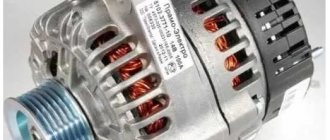
Generator circuits
This section presents a diagram of a VAZ 2108 generator of two types. One of them is a 2108 carburetor generator circuit designed for the model 37-3701 generator mounted on carburetor engines. Another connection diagram for the VAZ 2108 generator is intended for the generator model 5102.3771, installed on cars with a VAZ-2111-80 injection engine.
Electrical circuit of generator 37.3701 carburetor engine
| Position number on the diagram | Explanation of position |
| 1 | generator VAZ 2108 model 37.3701 |
| 2 | negative valve |
| 3 | additional diode |
| 4 | positive valve |
| 5 | low battery warning light |
| 6 | dashboard |
| 7 | voltmeter |
| 8 | fuse block |
| 9 | additional resistors 100 Ohm, 2W |
| 10 | ignition switch |
| 11 | ignition switch |
| 12 | source of electricity |
| 13 | capacitor |
| 14 | rotor winding |
| 15 | voltage regulator |
The generator model 37.3701 is mounted on VAZ 2108 cars with carburetor engines.
Generator circuit 5102.3771 injection engine
| Position number on the diagram | Explanation of position |
| 1 | source of electricity |
| 2 | generator VAZ 2108 model 5102.3771 |
| 3 | Relay and fuse box |
| 4 | low battery warning light located on the instrument panel |
| 5 | ignition switch |
On a car with an injection engine mod. VAZ-2111-80 was standardly equipped with generator 5102.3771 (Russia), but generator 94.3701 can be installed instead.
The voltage to excite the generator when the ignition is connected is supplied to the “D+” contact of the regulator (the “D+” terminal of the generator) through control 4 located on the dashboard. When the ignition is connected, the light should glow, and after starting the engine, it should go out if the generator is working. A bright glow of the light bulb or its burning at full intensity indicates a malfunction of the generator.
Electrical circuit for testing a generator on a bench
Electrical circuit for checking a generator with an oscilloscope
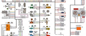
VAZ 2109 wiring diagram
The VAZ 2109 car has remained one of the most popular in the country for many years. Not just popular, but also prestigious. In the social hierarchy, owners of nines were not much lower than owners of used Cadets and Jettas. One could argue with the reliability of the car, but since there was no alternative, the car filled the entire CIS and was even assembled using the hub method in Finland, but this has little to do with the 2109 model.
This is interesting: Cars with Euro license plates are a tasty morsel for car thieves
Content:
Wiring diagram VAZ 2109
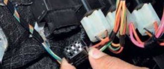
Like the entire car, the electrical equipment was not at the highest level, so owners of nines should know the VAZ 2109 wiring diagram thoroughly. To do this, we have provided the factory diagram in good resolution, which can be used with adjustments for changes made from time to time.
This is a diagram of the canonical nine with factory markings and explanations. In principle, the circuit is quite simple, but the electrical appliances themselves caused difficulties, the problems with which we will talk.
Basic problems with electrical wiring 2109
The biggest problem with the electrical equipment of the VAZ 2109 was the low quality of components and unsatisfactory build quality. Despite the fact that Togliatti traditionally blames suppliers for all mortal sins, in the end we have to take the rap, and as ordinary users, we should not be interested at all in why the spirals on the double-filament rear light bulbs constantly burn out. Also, in principle, we don’t care which factory made the housing for the fuse box - we only see the inadequate operation of the electrical equipment when pressing the brake pedal turns on the right turn.
And a lot of such examples can be given. If the factory is not confident in the quality of the components, then why install them on the car. Therefore, rhetorical questions only lead to unnecessary vibrations in the air, and do not solve the problem. The above problem with feet can be solved quite simply:
- the rear light cover is removed;
- the power terminals are disconnected from the trunk;
- the entire strip on which the lamps are mounted is unscrewed;
- The contact on the flexible board at the point of attachment to the lamp socket is checked.
Short circuits of the tracks of this board occur due to contamination of the contacts and tracks. Then the signal sent to the stop lamp can simply be redirected to the turn signal lamp. This can be radically solved by replacing the entire board with a new one, but the new strip will not last as long as we would like due to poor sealing of the lamp from inside the luggage compartment. It seems like a trifle, but we spend precious time solving trivial problems that are solved at the production level with the right approach, not the VAZ approach.
Improvements and correction of factory errors
In light of the above, a breakdown of the electronics control unit is very typical for the nine. The reason is very simple - its body simply allows water, dust and moisture in the form of condensation to pass through. Its very placement on the air supply shelf is not entirely clear, but there are also more significant disadvantages that can be eliminated with your own hands. The factory provided a tiny groove to drain water from the housing, but it constantly gets clogged, the housing fills with water, and the control unit slowly and surely dies. It is not cheap, so such negligence of the designers cannot be explained. There are two ways out of the situation - constantly clean the water drainage channel, or change the block at least once a year.
It is also worth paying attention to the fact that the power wiring on the bottom shelf of the radiator is constantly exposed to high temperatures. In addition, in this place it is in no way protected from water and dirt. This is also a difficult moment to explain. The category of wiring harness oversights includes the harness under the carpet next to the driver's seat. Moisture constantly accumulates there, and in order to remove it, you need to dry the floor, inevitably tugging on the rope. Of course, this problem cannot be solved on your own - the amount of work required to re-tighten all the wiring in the car is too large.
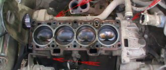
It is worth paying special attention to the power terminals on the generator. They very often become loose, heat up, spark and melt the wiring. But that's not the worst thing. The wires may short out, and it already smells burnt. Therefore, you should not be lazy, but check this unit as often as possible for tightness of the terminals.
Wire harness insulation 2109
No one will disassemble half a car for the sake of insulating the harnesses, but if necessary, you need to do this for your own safety. Using the diagram that we placed at the beginning of the article, all the work will not take much time, but you will be confident in the quality of the wiring insulation. For this you will need:
- Corrugated hose for electrical wires.
- Insulating tape.
- Wire cleaner.
Before wrapping old wiring in a sleeve, treat the wires with a cleaner, which is widely available in aerosol cans. Next, following the instructions and checking the electrical diagram, we proceed as follows:
- Disconnecting the battery
- Disconnect the terminals and remove the harness.
- We treat it with an aerosol.
- We carry out a visual check of the contacts.
- We lay the tourniquet in the corrugation.
- We fix and seal the entry points of the harness into the corrugation.
- We put the finished cable in place.
- Referring to the diagram, connect the terminals.
Particular attention should be paid to sealing the harnesses in places where they come into direct contact with water or hot surfaces. Also, when assembling, pay attention to the integrity of the pads and the condition of the contacts and terminals.
Thus, having spent very little time, we will save the wiring and get rid of unnecessary problems with short circuits. Keep an eye on the wiring, and good luck on the road!
Electrical diagram for connecting the VAZ 2108 starter
| Position number on the VAZ diagram | Explanation of the position on the diagram |
| 1 | starter VAZ 2108 brand 2113-3708010-00 or 29.3708, 423.3708. |
| 2 | source of electricity |
| 3 | magneto |
| 4 | Relay and fuse box |
| 5 | ignition switch |
| P1 | pull-in coil of traction relay |
| P2 | holding winding of the traction relay for connecting the starter |
A starter of brand 2113-3708010-00 from the Pramo company, produced in Russia, was installed on the car, but starters of brand 29.3708, 423.3708 can be installed. All starters are a DC electric motor with mixed excitation and an electromagnetic two-winding traction relay.
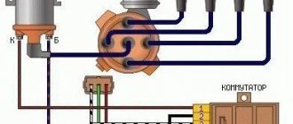
Ignition circuit 2108
Here is a diagram of the contactless ignition of the VAZ 2108. The 2108 ignition connection diagram includes the 2108 switch and its connection diagram, as well as other devices, a list of which is given in this section.
| Position number on the VAZ diagram | Explanation of the position on the diagram |
| 1 | contactless sensor |
| 2 | ignition distributor sensor VAZ 2108 brand 40.3706 or 40.3706-01, |
| 3 | spark plugs |
| 4 | switch |
| 5 | Ignition solenoid |
| 6 | Relay and fuse block |
| 7 | ignition switch |
| 8 | ignition switch |
Equipment for the contactless ignition system of the VAZ 2108 car:
- Ignition distributor sensor - 40.3706 or 40.3706-01;
- Switch - 3620.3734, or 76.3734, or RT1903, or PZE4022;
- Ignition coil - 3122.3705 with a closed magnetic circuit, dry or type 8352.12
- Spark plugs - A17DVR, or A17DVRM, or A17DVRM1, or FE65PR, or FE65CPR
Important ! You need to carry a Hall sensor and a switch in your car. The breakdown of these devices is quite large, and it is impossible to repair them or replace them with another one. If they break, the engine cannot be started, but changing them is easy. The same applies to the ignition coil, but it is more durable than the sensor and switch. If absolutely necessary, it can be replaced with a solenoid from another car.
Important ! Electronic ignition circuit for the injection engine of the VAZ-2111-80 model of the VAZ 2108 passenger car.
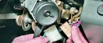
Signs of a faulty switch: how to check the switch yourself.
Purpose and design features of the switch.
A switch is one of the elements of a car's electrical equipment. Its task is to ensure the normal operation of the contactless ignition system. The assembly is fastened in the engine compartment.
The device is reliable, able to withstand severe vibrations and shock loads
This is very important, because the switch housing contains sensitive electronics
The VAZ switch is based on a standard L 497 microcircuit, which controls an “NPN” type transistor.
A special feature of the circuit is the possibility of programming by the user and setting the required delay coefficient. Starting a cold engine directly depends on the correctness of this indicator.
Thanks to precise tuning, you can speed up the crankshaft rotation speed (while eliminating failures in operation) and guarantee high-quality traction of the power unit.
The main parameters of the switch device include:
Voltage range – from 6 to 16 Volts; operating voltage level – 13.5 Volts; ensuring an uninterrupted spark when the crankshaft rotates in the range from 20 to 7000 rpm; switching current – from 7.5 to 8.5 A.
Signs of a faulty switch.
One of the main symptoms of a faulty switch is loss of spark. The engine starts hard and stalls from time to time, causing interruptions in operation.
But there is no need to rush into replacement - it is important to make sure of the reason, because loss of spark can occur for a number of reasons - failure of the Hall sensor, broken timing belt, faulty ignition coil, poor contact in the distributor cap, problems in the wiring, and so on. If the diagnostics of the remaining nodes did not produce results, then we can move on to our “hero”
But how to check the switch, since the device has a very complex design?
If the diagnosis of the remaining nodes does not produce results, then we can move on to our “hero”. But how to check the switch, since the device has a very complex design?
How to check the switch yourself.
Most car enthusiasts don’t bother with diagnostics and simply install a new unit. This method has its advantages. Firstly, there is no need to waste time checking - just install a new part.
Secondly, you can immediately determine whether this is the reason or not. In fact, there is no need to be afraid of the work, because checking the switch takes a few minutes.
So, to carry out work at home, a test lamp (nominal voltage should be 12 Volts) and a standard set of keys are enough.
With their help, you can verify the presence or absence of pulses, and later make a decision about the serviceability of the device itself.
Algorithm for checking the switch:
To begin work, it is advisable to disconnect the battery so as not to accidentally short-circuit the wiring that you will unscrew.
Using an eight-point wrench, unscrew the nut and remove the wiring from the ignition coil marked “K”. This wire is easy to recognize - it is brownish in color and goes to the terminal labeled one on the switch;
Connect this wire through a control light to terminal “K” on the ignition coil, and then connect the battery;
Turn on the engine starter and observe the lamp's actions. If it blinks, then the switch is working. If the light bulb does not show any signs of life, then the only way out is to replace the device.
If there are doubts about the serviceability of a part, the check should be carried out on a special stand (there is always one at the service station).
In this case, it is possible not only to determine whether the product is working, but also to measure the duration of the pulses.
When the first suspicions appear, you should not immediately change the switch or spend money on a specialist. You are quite capable of doing the job yourself.
Moreover, now you know how to check the switch on the VAZ 2109 and other models of the domestic brand. All that remains is to allocate time and prepare a minimum set of tools. Have a good trip and of course no breakdowns.
The task of the VAZ 2107 ignition system is to generate a spark that ignites the air-fuel mixture in the cylinders. In older “classic” models, this works based on the “breaker-ignition coil” connection. On more modern cars, a contactless ignition system is installed, where the VAZ 2107 ignition switch is responsible for sparking.
Switch malfunctions affect the efficiency and performance of the entire ignition system and the vehicle as a whole. Therefore, it will not be superfluous to learn how to check the VAZ 2107 switch and replace it, if necessary.
Wiring diagram for windshield wiper and washer
| Position number on the VAZ diagram | Explanation of the position on the diagram |
| 1 | motor with gearbox for windshield wipers |
| 2 | thermobimetallic fuse |
| 3 | electric motor for washer pump VAZ 2108 brand 33.5205 |
| 4 | electromagnetic throttle for windshield washer |
| 5 | relay and fuse block |
| 6 | ignition lock |
| 7 | ignition switch |
| 8 | switch for windshield wipers and washer |
| K3 | windshield wiper switch |
| A | sequence of conditional numbering of contacts in the wiper block |
| B | to terminal “30” of the generator |
| A | 2nd speed cleaner brush |
| b | 1st speed cleaner brush; |
| V | limit switch spring plate |
| g, d | limit switch contact posts |
| C1, C2 | noise suppression capacitors |
| L1, L2 | chokes |
Windshield wipers are available from domestic or Hungarian manufacturers. They are interchangeable in connection and mounting dimensions. The motors with gearboxes of these devices are also interchangeable, although they have some differences in design.
Wiring diagram for windshield wiper 2108 tailgate glass
| Position number on the VAZ diagram | Explanation of the position on the diagram |
| 1 | electric washer pump motor |
| 2 | electromagnetic throttle for connecting the rear window washer |
| 3 | Relay and fuse box |
| 4 | ignition switch |
| 5 | switch for windshield wipers and washer |
| 6 | rear window cleaner |
| A | to contact "30" magneto |
| B | plan for conditional numbering of contacts in the terminal block of the rear window wiper |
On some cars, tailgate glass cleaners may be installed along with electromagnetic washer chokes.
Full scheme
The order of conditional numbering of plugs in blocks:
a – mounting block, instrument cluster, ignition switch and windshield wiper (for blocks with a different number of plugs, the numbering order is similar); b – ignition distributor sensor; c – switch and carburetor solenoid valve control unit; d – headlight units, headlight and rear window cleaners; g – interior lighting lamp; e – fuel level sensor; d – rear lights (pin numbering in order from top to bottom)
* Installed on parts of manufactured cars. ** Not installed since 1995.
Heater fan motor connection diagram
| Position number on the VAZ diagram | Explanation of the position on the diagram |
| 1 | Relay and fuse block for VAZ 2108 |
| 2 | ignition switch |
| 3 | additional resistor |
| 4 | electric heater fan motor VAZ 2108 brand 45.3730 |
| 5 | heater electric motor switch |
| A | to terminal "30" magneto |
Electrical diagram of the rear window heating system
| Position number on the VAZ diagram | Explanation of the position on the diagram |
| 1 | Relay and fuse box |
| 2 | rear window heating connector |
| 3 | ignition switch |
| 4 | rear window heating switch; |
| 5 | rear window heating connection control |
| 6 | rear window heater |
If the glass does not warm up when the heating is connected, you need to check fuse F4, the wires and their connections, as well as the switch and relay 2.
If the rear window heater breaks down, the manufacturer recommends replacing the entire glass, but now the retail chain has special kits for repairing broken heater threads, which consist of the necessary components, tools and instructions for use.
The microprocessor ignition system is equipped with:
- one coil, which is common to the nodes;
- dual or individual voltage generation device.
Each option has distinctive features:
- the common coil is mounted in devices with microprocessor ignition equipped with a distributor;
- an individual type of coil is mounted on a spark plug, which eliminates the need to install high-voltage conductors;
- Dual-type coils are mounted in direct ignition units. So, a pair of coils are mounted on a 4-cylinder engine. One is installed on a pair of cylinders 1 and 4, and the second on 2 and 3. A high voltage current is generated in each device. A spark is formed simultaneously in two combustion chambers. In one, the prepared fuel mixture ignites, and in the other, the spark works in vain.
Connection diagram for the VAZ 2108 instrument cluster with a “low” panel (rear view)
| Position number on the VAZ diagram | Explanation of the position on the diagram |
| A | plan for conditional numbering of terminals in the instrument cluster blocks |
| A | PCB joints for instrument cluster without socket 17 |
| 1 | voltmeter |
| 2 | instrument lighting bulbs |
| 3 | antifreeze heat indicator |
| 4 | rear window heating control |
| 5 | high beam headlight control |
| 6 | backup control |
| 7 | rear fog light indicator light |
| 8 | size control |
| 9 | direction indicator control |
| 10 | "STOP" indicator light |
| 11 | oil pressure check |
| 12 | handbrake indicator light |
| 13 | emergency signal control |
| 14 | checking the brake fluid level; |
| 15 | carburetor throttle warning light |
| 16 | battery discharge control |
| 17 | socket for the relay-interrupter of the handbrake indicator light |
| 18 | gasoline level indicator |
| 19 | fuel reserve control |
The connections of the instrument cluster are made by printed wiring on a foil getinax plate. The plate is attached to the back of the case.
Diagram of the VAZ-2104 dashboard, control sensors
The driver monitors the operation of the power plant and car systems using sensors installed on the dashboard in the cabin.
I – temperature sensor; II – instrument panel; III – oil pressure lamp; IV – gasoline level sensor; V – circuit diagram for connecting electrical devices.
| 1 | Thermistor | 27 | Voltmeter |
| 2 | Contact spring | 28 | Dashboard |
| 3 | cylinder head | 29 | Gasoline level indicator |
| 4 | Paper insulation | 30 | Fuel reserve warning lamp |
| 5 | Frame | 31 | PTF rear light switch |
| 6 | Lid | 32 | Lubricant Pressure Sensor Filter |
| 7 | Pointer balancer | 33 | Spring |
| 8 | Permanent magnet arrow axis | 34 | Movable contact |
| 9 | Frame with sensor coils | 35 | Fixed contact (massed) |
| 10 | Protection diode | 36 | Diaphragm |
| 11 | External lighting switch | 37 | Crankcase |
| 12 | Oil pressure lamp | 38 | Reserve warning lamp contact |
| 13 | Coolant temperature gauge | 39 | Rheostat |
| 14 | Battery charge indicator lamp | 40 | Rheostat moving contact |
| 15 | Control lamp block | 41 | Gasoline level and reserve sensor |
| 16 | Brake fluid level lamp | 42 | Float with lever |
| 17 | Handbrake lamp | 43 | battery |
| 18 | PTF switching lamp | 44 | Generator |
| 19 | Speedometer | 45 | Oil pressure sensor |
| 20 | Odometer | 46 | Coolant temperature sensor |
| 21 | Rear defogger switch | 47 | Brake fluid level sensor |
| 22 | Dashboard mounting screw caps | 48 | Mounting block |
| 23 | Interior ventilation and heating fan switch | 49 | Egnition lock |
| 24 | High beam warning light | 50 | Handbrake lamp breaker relay |
| 25 | Turn signal lamp | 51 | Handbrake lamp switch |
| 26 | Exterior lamp |
Devices that provide comfort include a heating and ventilation system, a cigarette lighter, and small lighting fixtures.
To ensure safety and prevent burnout of electrical appliances, all wiring is insulated. Additionally, all equipment is powered through fuses, which are collected in one unit. That is, for example, if the dimensions do not work, there is a high probability that there is a short circuit in the electrical wiring through which these lighting devices are powered. The electrical diagram of the VAZ-2104 fuse box is printed on its cover, which allows you to quickly find which section of the circuit and equipment fuse has blown.
Books and diagrams for repairing VAZ 2108
Here you can download the following books on the repair and operation of the VAZ 2108 passenger car and its modifications.
- Catalog of spare parts for VAZ-2108, VAZ-2109 cars and their modifications / 1992
- 160 pp.
- Size - 72.8 MB
- Format - pdf
- 1989
- 1996