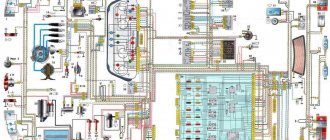
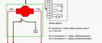
Diagram of the engine control system (ECM) VAZ-2113, 2114 and 2115
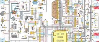
Engine control system (ECM) diagram Euro-2 Bosch 7.9.7, January 7.2 VAZ-2113, 2114 and 2115 (2111-1411020-80, 81.82). Engine 1.5 liter 8 valve.
- — controller;
- — block of the ignition system harness to the ABS cabin group harness;
- — diagnostic block;
- — immobilizer warning sensor (APS);
- — immobilizer control unit (APS);
- - ignition coil;
- - spark plug;
- — nozzles;
- — electric fuel pump;
- — block of the ignition system harness to the electric fuel pump harness;
- — block of the fuel level sensor harness to the ignition system harness;
- — block of the ignition system harness to the injector harness;
- — block of the injector harness to the ignition system harness;
- - speed sensor;
- — idle speed regulator;
- — throttle position sensor;
- — coolant temperature sensor;
- — mass air flow sensor;
- — camshaft position sensor (phases);
- — oxygen sensor;
- — crankshaft position sensor;
- - knock sensor;
- — solenoid valve for purge of the adsorber;
- — block of the ignition system harness to the instrument panel harness;
- — controller power supply fuse;
- - ignition relay;
- — ignition relay fuse;
- — fuse for the power supply circuit of the electric fuel pump;
- — electric fuel pump relay;
- — electric fan relay;
- — block of the ignition system harness to the air conditioning harness;
- — pads of the ignition system harness to the front harness;
- — electric cooling system fan;
- — block of the instrument panel harness to the ignition system harness;
- — ignition switch;
- — instrument cluster;
- — on-board control system unit;
- - starter relay;
- — mounting block;
- A - to the “plus” terminal of the battery; B1, B2 - grounding points of the ignition system harness; 2115-3724026-11 — Ignition system harness;
Diagram of the engine control system (ECM) Euro-2 Bosch 7.9.7, January 7.2 VAZ-2113, 2114 and 2115 (21124-1411020-30, 21124-1411020-31.32). 1.6 liter 16 valve engine with individual ignition coils.
- — block of the ignition coil wiring harness to the ignition system harness;
- — block of the ignition system harness to the ignition coil wiring harness;
- — ignition coils;
- — immobilizer warning sensor;
- — immobilizer control unit;
- - spark plug;
- — nozzles;
- — diagnostic block;
- — block of the ignition system harness to the ABS cabin group harness;
- — controller;
- — electric fuel pump;
- — block of the ignition system harness to the fuel level sensor harness;
- — block of the fuel level sensor harness to the ignition system harness;
- — block of the ignition system harness to the injector harness;
- — block of the injector harness to the ignition system harness;
- — block of the ignition system harness to the side door harness;
- - speed sensor;
- — idle speed regulator;
- — throttle position sensor;
- — coolant temperature sensor;
- — mass air flow sensor;
- — oil pressure warning lamp sensor;
- — camshaft position sensor (phases);
- — oxygen sensor;
- — crankshaft position sensor;
- - knock sensor;
- — solenoid valve for purge of the adsorber;
- —
- — coolant temperature indicator sensor;
- — block of the ignition system harness to the instrument panel harness;
- — block of the instrument panel harness to the ignition system harness;
- - ignition relay;
- — ignition relay fuse;
- — fuse for the power supply circuit of the electric fuel pump;
- — electric fuel pump relay;
- — electric fan relay;
- — controller power supply fuse;
- — ignition system harness block to the air conditioner connector;
- — instrument cluster;
- — ignition switch;
- — electric cooling system fan;
- — on-board control system unit;
- — additional starter relay;
- — contacts of the 8-terminal blocks of the instrument panel harness and the front harness;
- — contacts of the 21-terminal blocks of the instrument panel harness and the rear harness;
- - trip computer;
- — diagnostic connector;
- A, E - to the “plus” terminal of the battery; B1 — grounding point of the ignition coil wiring harness; B2 — grounding point of the fuel level sensor harness; B3, B4 - grounding points of the ignition system harness; C - to the starter; D — to the driver's door interior lamp switch;
Diagram of the engine control system (ECM) Euro-3 Bosch 7.9.7+, M73 VAZ-2113, 2114 and 2115 (2111-1411020-30). Engine 1.6 liter 8 valve.
1 - controller; 2 — block of the ignition system harness to the ABS cabin group harness; 3 — diagnostic block; 4 — immobilizer warning sensor (APS); 5 — immobilizer control unit (APS); 6 — ignition coil; 7 — spark plugs; 8 — nozzles; 9 — electric fuel pump; 10 — block of the ignition system harness to the fuel level sensor harness; 11 — block of the fuel level sensor harness to the ignition system harness; 12 — block of the ignition system harness to the injector harness; 13 — injector harness block to the ignition system harness; 14 — speed sensor; 15 — idle speed regulator; 16 — throttle position sensor; 17 — coolant temperature sensor; 18 — mass air flow sensor; 19 — camshaft position sensor (phases); 20 — control oxygen sensor; 21 — crankshaft position sensor; 22 — knock sensor; 23 — solenoid valve for purge of the adsorber; 24 — rough road sensor; 25 — diagnostic oxygen sensor; 26 — block of the ignition system harness to the instrument panel harness; 27 — controller power supply fuse; 28 — ignition relay; 29 — ignition relay fuse; 30 — fuse for the electric fuel pump power supply circuit; 31 — electric fuel pump relay; 32 — electric fan relay; 33 — block of the ignition system harness to the air conditioner harness; 34 — pads of the ignition system harness to the front harness; 35 — electric fan of the cooling system; 36 — block of the instrument panel harness to the ignition system harness; 37 — ignition switch; 38 — instrument cluster; 39 — on-board control system unit; 40 — starter relay; 41 — mounting block;
A - to the “plus” terminal of the battery; B1 — grounding point of the fuel level sensor harness; B2, B3 - grounding points of the ignition system harness;
Diagram of the engine control system (ECM) Euro-3 Bosch 7.9.7+, M73 VAZ-2113, 2114 and 2115 (21124-1411020-10). 1.6 liter 16 valve engine with individual ignition coils and two oxygen sensors.
1 — block of the ignition coil wiring harness to the ignition system harness; 2 — block of the ignition system harness to the ignition coil wiring harness; 3 — ignition coils; 4 — immobilizer warning sensor; 5 — immobilizer control unit; 6 — spark plugs; 7 — nozzles; 8 — diagnostic block; 9 — block of the ignition system harness to the ABS cabin group harness; 10 - controller; 11 — electric fuel pump; 12 — block of the ignition system harness to the fuel level sensor harness; 13 — block of the fuel level sensor harness to the ignition system harness; 14 — block of the ignition system harness to the injector harness; 15 — injector harness block to the ignition system harness; 16 — block of the ignition system harness to the side door harness; 17 — speed sensor; 18 — idle speed regulator; 19 — throttle position sensor; 20 — coolant temperature sensor; 21 — mass air flow sensor; 22 — oil pressure warning lamp sensor; 23 — camshaft position sensor (phases); 24 — control oxygen sensor; 25 — crankshaft position sensor; 26 — knock sensor; 27 — solenoid valve for purge of the adsorber; 28 — diagnostic oxygen sensor; 29 — coolant temperature indicator sensor; 30 — block of the ignition system harness to the instrument panel harness; 31 — block of the instrument panel harness to the ignition system harness; 32 — ignition relay; 33 - ignition relay fuse; 34 — fuse for the electric fuel pump power supply circuit; 35 — electric fuel pump relay; 36 — electric fan relay; 37 — controller power supply fuse; 38 — ignition system harness block to the air conditioner connector; 39 — rough road sensor; 40 — instrument cluster; 41 — ignition switch; 42 — electric fan of the cooling system; 43 — on-board control system unit; 44 - additional starter relay; 45 — contacts of the 8-terminal blocks of the instrument panel harness and the front harness; 46 — contacts of the 21-terminal blocks of the instrument panel harness and the rear harness; 47 — trip computer; 48 — diagnostic connector;
A, E - to the “plus” terminal of the battery; B1 — grounding point of the ignition coil wiring harness; B2, B3 - grounding points of the ignition system harness; B4 — grounding point of the fuel level sensor harness; C - to the starter; D — to the driver's door interior lamp switch;
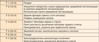
Bosch M1.5.4
The pinout of the VAZ 2114 Bosch M1.5.4 ECU connector is as follows:
- 1, 20 – Control of ignition coils of cylinders 1, 4 and 2, 3;
- 3 – fuel pump;
- 4, 21, 26, 29 – Contact A, C, B, D IAC;
- 6 – fan;
- 7 – mass air flow sensor;
- 9 – speed sensor;
- 11 – DD;
- 12 – +5V output for powering sensors;
- 13 – L-line;
- 14 – mass of injectors;
- 15, 33 – control of turning on the injectors of cylinders 1, 4 and 2, 3;
- 18 – positive terminal of the battery;
- 19, 24 – mass;
- 22 – Check Engine indicator;
- 25 – air conditioner;
- 27 – positive pole from the ignition switch;
- 30 – mass of sensors;
- 34 – voltage output from the main relay;
- 41 – on air conditioner;
- 43 – tachometer;
- 44 – CO sensor;
- 45 – DTOZH. Terminal B;
- 46 – voltage at the output of the main relay;
- 47 – programming;
- 48, 49 – DPKV. Terminals B, A;
- 53 – TPDZ. Terminal C;
- 54 – fuel consumption level;
- 55 – k-Line.
VAZ-2112 diagram
The VAZ-2112 car was produced at AvtoVAZ from 1998 to 2009, in Ukraine from 2009 to 2014. The following are color wiring diagrams (injector and carburetor) with a description of all elements for various modifications. The information is intended for self-repair of cars. Electrical circuits are divided into several blocks for ease of viewing via a computer or smartphone; there are also circuits in the form of a single picture with a description of the elements - for printing on a printer in one sheet.
To diagnose and repair yourself, first look to see if everything is okay with the generator. Is it put on well and does not sag? This procedure must be done with all versions of the fuel system, both carburetor and injection. We check the fuses according to the electrical diagram. The reverse side of the safety block cover will also be of great help. There are clues there that the diagram will help you decipher. Replace the burnt out element and try to start the car again. You need to check whether the battery terminals are tightly connected and whether they are oxidized. Is the wire going from the battery to the generator and to the starter damaged?
Basic tips for working with automotive electronics
Let’s immediately agree that installation, removal and any other work with car wiring are the most complex operations, which are taught in secondary specialized educational institutions. This article is for informational purposes only on working with the electronics of VAZ models and contains solely a description of the basic aspects of these procedures, so it will not be possible to learn from it all the intricacies of wiring repairs. Familiarization with these lies only through long and hard work associated with work practice in the field of automobile repair.
Returning to the main topic of today’s material, it would not be out of place to note: even a person without special skills in this path has the opportunity to install the wiring of any car with his own hands. However, for proper implementation of all procedures it is extremely important:
- Have the necessary diagrams that connect the wiring to a specific engine and dashboard. You can find them either when purchasing certified parts or the machine itself, or on the World Wide Web;
- Know the basics of working with automotive electronics, which we will get acquainted with in this article;
- Find free time, a small amount of tools and a place for repair work.
Modifications of the VAZ-2112 car
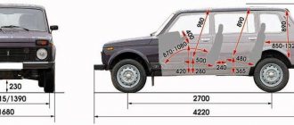
VAZ-21120 . Modification with a 16-valve injection engine with a volume of 1.5 liters and a power of 93 horsepower. 14-inch wheels were installed on the car. This modification has a problem with valves bending when the timing belt breaks. The problem can be solved by increasing the depth of the grooves in the piston bottoms.
VAZ-21121 . The car was equipped with a VAZ-21114 8-valve injection engine with a volume of 1.6 liters and a power of 81 horsepower.
VAZ-21122 . Budget modification with an 8-valve injection engine VAZ-2111. The car was produced without electric windows, the wheels were 13 inches in size, and the brakes were unventilated from a VAZ-2108 car.
VAZ-21123 Coupe . Three-door, five-seater hatchback. The only two doors for entering the car are 200 millimeters wider than those of the five-door hatchback, and they are mounted on new, durable hinges. The rear arches of the car have become wider. The engine was installed with a 16-valve injection engine with a volume of 1.6 liters and a power of 90 horsepower. The car was produced from 2002 to 2006 in small quantities, the reason for this was the high cost of the car.
VAZ-21124 . Modification with a 16-valve injection engine VAZ-21124 with a volume of 1.6 liters. Produced from 2004 to 2008. For this type of engine, the problem with valve bending was solved. To do this, the depth of the grooves in the piston heads was increased (up to 6.5 mm). In addition, the design of the cylinder block was changed to achieve a working volume of 1.6 liters, for which its height was increased by 2.3 mm, and the radius of the crankshaft was increased by 2.3 mm accordingly. There were also a number of other minor changes.
VAZ-21128 . The luxury version of the car, produced by Super-auto JSC, was equipped with a 16-valve VAZ-21128 engine with a volume of 1.8 liters and a power of 105 horsepower.
VAZ-2112-37 . A racing modification of the VAZ-2112, prepared for the “ring” in the Lada Cup qualifying group. The car was equipped with a 1.5-liter VAZ-2112 engine with a power of 100 horsepower. The racing car was equipped with a safety cage, an external aerodynamic kit and a front extension of the strut support cups.
VAZ-2112-90 Tarzan . All-wheel drive modification with a VAZ-2112 body on a frame chassis with transmission and suspension parts from a VAZ-21213 Niva. It was also equipped with a 1.7 or 1.8 liter engine from the Niva.
Differences from its predecessor
The VAZ 2115 car is a more modernized version of model 21099. The improvement of the “ninety-nine” contributed to the updating of the electrical wiring diagram.
It should be noted that, unlike 21099, the VAZ 2115 injector is equipped with newer body parts, in particular, we are talking about:
- improved shape of the front wings;
- the appearance of the headlights;
- back panel shape;
- different shape of the hood and luggage compartment.
Toy models VAZ 21099 and VAZ 2115
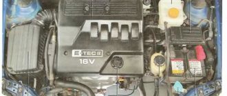
Of course, the changes also affected the engine compartment. Compared to 21099, the VAZ 2115 is equipped with a more powerful engine. Changes also affected the interior - a more advanced center console, instrument panel, and seats. An on-board computer was also added to the design of the car. Accordingly, the overall dimensions of the VAZ 2115 also underwent changes. But in general, this car remained the same - a front-wheel drive, five-door and five-seater sedan.
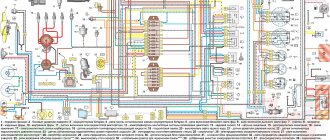
Electrical diagram of VAZ-2112
Designations: 1 – Headlight, 2 – Klaxon, 3 – Main radiator fan, 4 – Starter, 5 – Battery, 6 – Generator 2112, 7 – Gearbox limit switch (reverse), 8 – Actuator in the front passenger door, 9 – Power window enable relay, 10 – Starter relay, 11 – Heater fan, 12 – Electric heater partition drive, 13 – Main pump, 14 – Washer reservoir sensor, 15 – Driver’s door actuator, 16 – Front passenger window selector, 17 – Unlock button fifth door, 18 – Heater fan resistance unit, 19 – Main wiper motor, 20 – Driver’s window lift selector, 21 – Front passenger’s window lift motor, 22 – Central locking, 23 – Exterior light switch, 24 – Brake fluid leakage sensor, 25 – Pump additional, 26 – Driver's window lift motor, 27 – PTF on indicator, 28 – PTF switch, 29 – Dashboard, 30 – Heated glass on indicator, 31 – Heated glass switch, 32 – Steering column selector switch, 33 – PTF relay, 34 – Ignition switch, 35 – Main fuse block, 36 – Illumination of heater controls, 37 – Hazard warning button, 38 – Heater control controller, 39 – Glove compartment lighting, 40 – Glove compartment lid end cap, 41 – Cigarette lighter, 42 – BSK – display unit, 43 – Ashtray illumination, 44 – 12V socket, 45 – Instrument lighting switch, 46 – Actuator in the right rear door, 47 – Right rear passenger window selector, 48 – Clock, 49 – Right rear passenger window motor, 50 – Brake limit switch (closed – pedal is pressed), 51 – Left rear passenger window motor, 52 – Left rear passenger window selector, 53 – Actuator in the left rear door, 54 – Turn signal, 55 – Handbrake limit switch (closed – handbrake on), 56 – Rear wiper motor , 57 – Navigator's lamp, 58 – Interior lamp, 59 – Temperature sensor in the heater, 60 – Limit switch for the open front door, 61 – Limit switch for the open rear door, 62 – Trunk light, 63 – Rear optics (on the body), 64 – Rear optics (on the fifth door), 65 – License plate illumination.
The letters indicate the terminals to which it is connected: A – Front speaker on the right, B – Radio, C – Injector harness, D – ESD diagnostic connector, D – Front left speaker, E – Diagnostic connector for the heater controller, G – Rear right speaker, W – Rear left speaker, I – BC connector, K – glass heater thread, L – fifth door actuator, M – Additional brake light.
Wiring diagram VAZ-2112 injector 16 valves - full view
VAZ-21124 engine control circuit
Connection diagram of the VAZ-21124 engine control system with distributed fuel injection to Euro-2 emission standards (controller M7.9.7): 1 - ignition coils; 2 — nozzles; 3 - controller; 4 - main relay; 5 - fuse connected to the main relay; 6 — cooling system electric fan relay; 7 - fuse connected to the cooling system electric fan relay; 8 - electric fuel pump relay; 9 - fuse connected to the electric fuel pump relay; 10 — mass flow and air temperature sensor; 11 — throttle position sensor; 12 — coolant temperature sensor; 13 — solenoid valve for purge of the adsorber; 14 — oxygen sensor; 15 — knock sensor; 16 — crankshaft position sensor; 17 — idle speed regulator; 18 — immobilizer control unit; 19 — immobilizer status indicator; 20 - phase sensor; 21 — vehicle speed sensor; 22 — electric fuel pump module with fuel level sensor; 23 — oil pressure warning lamp sensor; 24 — coolant temperature indicator sensor; A - block connected to the wiring harness of the ABS cabin group; B — diagnostic block; B - block connected to the air conditioner wiring harness; G - to the “+” terminal of the battery; D — to the side door wiring harness block; E - block connected to the instrument panel wiring harness; G1, G2 - grounding points; I - the order of conditional numbering of plugs in the block of the immobilizer control unit; II - the order of conditional numbering of contacts in the diagnostic block.
Connection diagram of the VAZ-21124 engine control system with distributed fuel injection under Euro-3 toxicity standards (controller M7.9.7): 1 - ignition coils; 2 — nozzles; 3 - controller; 4 - main relay; 5 - fuse connected to the main relay; 6 — cooling system electric fan relay; 7 - fuse connected to the cooling system electric fan relay; 8 - electric fuel pump relay; 9 - fuse connected to the electric fuel pump relay; 10 — mass flow and air temperature sensor; 11 — rough road sensor; 12 — throttle position sensor; 13 — coolant temperature sensor; 14 — idle speed regulator; 15 — control oxygen sensor; 16 — diagnostic oxygen sensor; 17 — solenoid valve for purge of the adsorber; 18 — knock sensor; 19 — crankshaft position sensor; 20 — immobilizer control unit; 21 — immobilizer status indicator; 22 - phase sensor; 23 — vehicle speed sensor; 24 — electric fuel pump module with fuel level sensor; 25 — oil pressure warning lamp sensor; 26 — coolant temperature indicator sensor; A - block connected to the wiring harness of the ABS cabin group; B — diagnostic block; B - block connected to the air conditioner wiring harness; G - to the “+” terminal of the battery; D — to the side door wiring harness block; E - block connected to the instrument panel wiring harness; G1, G2 - grounding points; I - the order of conditional numbering of plugs in the block of the immobilizer control unit; II - the order of conditional numbering of contacts in the diagnostic block.
ECU January-4
The January 4 electronic control unit has three connectors, which differ in color and number of contacts. The pinout is as follows:
Pink connector 24 pins:
- A1-A4 – common wire of the on-board network (ground);
- A8, A9 – ignition coil of cylinders 2, 3 and 1, 4;
- A11 – +5V output for powering sensors;
- A12, B8 – positive pole of the battery;
- B2 – tachometer signal;
- B3 – air conditioner clutch;
- B4 – speed signal;
- B5 – adsorber, purge valve control;
- B6 – mass air flow sensor;
- B7 – coolant temperature;
Pink connector 32 pins:
- C1 – positive voltage 12 V from the ignition switch;
- C2 – DD;
- C3 – fuel pump;
- C5 – L-line;
- C12, D8 – control of turning on the injectors of cylinders 2, 3 and 1, 4;
- C16, D16 – mass and signal of the λ-probe (oxygen sensor);
- D10 – air conditioner;
- D16 – DC;
- Blue connector 32 pins:
- C2 – fuel consumption;
- C5, C6 – idle, high and low levels A;
- C7, C8 – idle, high and low levels B;
- C9 – speed sensor;
- C12 – coolant mass;
- C16, D16 – DPKV. High and low levels;
- D1, D12 – TPS signal and mass;
- D2 – fan;
- D4 – k-Line;
- D5 – Check Engine indicator;
VAZ-2112 harness diagrams
Instrument panel harness diagram
1, 2, 3, 4 – instrument panel harness pads to the front harness; 5 — block of the instrument panel harness to the side door harness; 6, 7, 8 — instrument panel harness pads to the rear harness; 9 – rear window heating switch; 10 – light signaling switch; 11 – windshield wiper switch; 12 – block of the instrument panel harness to the radio; 13 – mounting block; 14 — instrument cluster; 15 – heater control controller; 16 – heater motor switch; 17 — block of the instrument panel harness to the ignition system harness; 18, 19 — blocks of the instrument panel harness to the air supply box harness; 20 — ignition switch; 21 – fog lamp relay; 22 – sound signal relay; 23 — power window relay; 24 — starter relay; 25 – seat heating relay; 26 – external lighting switch; 27 – fog lamp switch; 28 – cigarette lighter; 29 – lampshade lighting of the glove box; 30 – glove box lighting switch; 31 – switch for rear fog lights; 32 – right steering column switch; 33 – socket for connecting a portable lamp; 34 — instrument lighting switch; 35 – brake signal switch; 36 – sound signal switch; 37 – alarm switch; 38 – air distribution drive gearmotor; 39 – VAZ-2112 illuminator; 40 — instrument panel harness block to the front harness; 41 – trunk lock drive switch; 42 – rear fog light relay.
A – grounding point of the instrument panel harness.
Wiring harness for injectors VAZ 1118 Kalina, 2170 Priora with a volume of 1.6L (8V).
Dear customers, in order to avoid errors when sending the wiring harness for injectors VAZ 1118 Kalina, 2170 Priora with a volume of 1.6 L (8 V) CARGEN, in the “Comment” line indicate the number of valves, engine size, model of your car, year of manufacture.
When operating an injection engine with an engine capacity of 1.6 L (8 V) Lada Kalina, Priora, the engine control computer 11183-1411020-20 constantly monitors the state of the executive equipment and their control circuits. For this, appropriate programs and drivers are used, which use the appropriate algorithm in their work. When such a program detects a malfunction of a particular device, the corresponding malfunction code is entered into the controller’s RAM memory and the “Check Engine” lamp lights up on the driver’s instrument panel.
If a break in the control circuit of one or more injectors is detected, fault code P0201 (P0202 – 0204) is entered into the controller’s RAM memory. This code corresponds to the number of the faulty injector (1-0201, 2-0202, etc.). If one of these malfunctions occurs, it is necessary to disconnect the contact block from the injectors and check the resistance between the terminals on it.
If the resistance of the terminals of all pads is in the range of 11 - 15 Ohms, then it is necessary to check the resistance of the non-working injector, which should also be 11 - 15 Ohms.
A resistance less than or greater than this value indicates a break or short circuit in the injector solenoid coil. This injector must be replaced.
If the injector is working properly, there may be a broken wire in the injector harness or a weak connection, as well as a broken wire between the injector harness block and the controller block. To check, you need to check the resistance in the injector control wire between the terminal of the controller block and the injector harness block. Resistance should not exceed 1 ohm.
Increased resistance indicates a wire break in the harness from the controller to the injector harness block.
If the wire from the controller to the injector harness block is in good condition, it is necessary to check the resistance of the corresponding wire directly in the injector harness by measuring the resistance. If the wire is in good condition, it is necessary to eliminate the presence of poor contact in the connection of the injector harness and the controller harness.
"Cargen" is constantly working to ensure that its products - automotive wiring harnesses - meet the needs of consumers. This made it possible to implement and certify a quality system for automotive wiring harnesses in accordance with the requirements of GOST R51814.1-2004 (ISO/TU 16949:2002).
Other article numbers of the product and its analogues in catalogues: 11186372403600.
VAZ 1117-1119, VAZ 2170-2172.
Any breakdown is not the end of the world, but a completely solvable problem!
How to independently replace the wiring harness for VAZ 1118 injectors on a car of the Lada Kalina, Priora family and their modifications with an engine capacity of 1.6 L (8 V).
AvtoAzbuka online store, repair costs will be minimal.
Just COMPARE and BE SURE.
Don't forget to share the information you find with your friends and acquaintances, because they may also need it - just click one of the social networking buttons located above.