Electrical wiring in a car plays an important role, connecting all electrical lines, electrical equipment and electronics. Therefore, when purchasing a new car, a service book with electrical diagrams is included. If there is a malfunction of any element in the on-board network, the driver will be helped by a diagram of the location of electrical equipment with wiring. The overview of the diagrams is designed to help beginners, as well as car enthusiasts who bought a used Lada Granta car without a diagram. In the event of a minor malfunction of any unit, an experienced driver can handle it himself, having a multimeter with him. The most important thing is to follow safety precautions when working with electrical equipment.
Grant norm central locking scheme
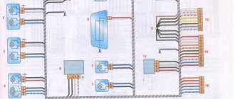
What controls the central locking? A special block to which the lock actuator wires fit. There are also two wires connected to it, connected to the driver's door microphone. More precisely, this wire is used alone in “Grant”, it has a brown sheath, and the second contact from the “micrik” is connected to ground.
The “micric” itself is located inside the actuator. So, the first piece of advice: after removing the left front door trim, you need to find the cable going from the actuator to the 7-pin connector.
Depending on the configuration, under the trim you will see the following:
- There are 6 wires suitable for the connector (from 2 microphones and a drive);
- The cords from the electric drive (pins “2/7”) are not connected, but there is still a brown wire connected to pin “1”;
- Only those wires that, according to the diagram, should be connected to contacts “4/6” are missing.
Connecting the signaling means that the wires from contacts “2/7” are still connected to the central locking control unit. The cords coming from the three actuators are always connected to the standard unit. You need to connect a fourth one, if this is not done by the factory. You may have to lay a two-wire cable from the door to the central lock control unit:
The central locking control unit is located under the fuse block, it is designated BUBD-2190.
Here's how one of the car owners coped with the task:
The cords that come out of the door are connected to the wires of the standard terminal block. The following connector pins are used: “3” and “4”. The main thing is not to confuse them. Take another look at the diagram to see what exactly we are talking about.
Instructions for installing headlights for dummies
The entire process of equipping a car with foglights can be divided into several stages:
- Removing the bumper.
- Installation of headlights.
- Wiring.
- Connecting headlights.
- Reassemble the parts in reverse order.
Removing the front bumper
The Granta's bumper is integral with the radiator grille, so in order not to distort the latches under the wings, it is advisable to remove it together with a partner.
Photo gallery: necessary tools
- crosshead screwdriver;
- 10 mm wrench, 10 mm socket;
- 8 mm wrench;
- TORX T-20 wrench.
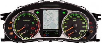
Lada Granta instrument panel diagram
Electrical connection diagram for the instrument panel harness : 1-block of the wiring harness of the wiring panel to the block of the front wiring harness; 2-block of the wiring harness of the wiring panel to the block of the front wiring harness; 3-block of the wiring harness of the wiring panel to the block of the rear wiring harness; 4-block of the wiring harness of the wiring panel to the block of the rear wiring harness; 5-lighting control module; 6-ignition switch; 7-on-board computer mode switch; 8-wiper switch; 9-instrument cluster; 10-light signaling switch; 11-switch for trunk lock drive; 12-block diagnostics; 13-block of the instrument panel wiring harness to the block of the wiring harness of the air supply box; 14-rear window heating switch; 15-hazard switch; 16-brake signal switch; 17-block of the instrument panel wiring harness to the radio; 18-block of the instrument panel wiring harness to the radio; 19-rotating device; 20-module driver airbag; 22-mounting block; 23-electric power steering; 24-cigarette lighter; 25-lamp illumination of the heater control panel; 26-illuminator; 27-block of the instrument panel wiring harness to the block of the ignition system wiring harness; 28-controller; 29-clutch pedal position signal switch; 30-electronic accelerator pedal; 31-additional resistor; 32-heater electric motor; 33-heater motor switch; 34-door lock system control unit.
Relay: K1-relay for the electric fan of the engine cooling system; K2-door lock activation relay; K3-additional starter relay; K4-additional relay; K5-relay-breaker for direction indicators and hazard warning lights; K6 wiper relay; K7-relay for turning on the high beam headlights; K8-horn relay; K9 relay for low beam headlights; K10-relay for turning on the heated rear window; K11-main relay; K12 fuel pump relay.
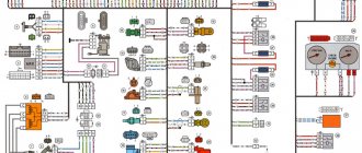
Ignition system wiring harness pinout diagram
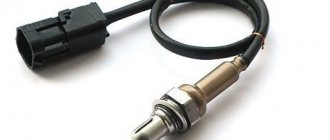
1 — oil pressure indicator; 2 — generator unit connector; 3 — throttle valve power supply; 4 — antifreeze temperature sensor; 5 — block of ignition system wire bundles to the block of instrument panel harnesses; 6 — power supply to the adsorber purge valve; 7 — speed sensor (speedometer); 8 — mass air flow sensor; 9 — DPKV; 10 — oxygen saturation sensor; 11 — control controller; 12 — oxygen saturation diagnostic sensor; 13 — ignition coil; 14 — spark plugs; 15 — nozzle control; 16 — blocks of ignition harnesses and injector wire bundles; 17 — detonation control sensor.
Connecting the signaling to the central locking system
Now we get to the most interesting part. The contacts of the signaling relay must be connected to the gap in the brown wire (see diagram in Chapter 1). Moreover, this will be required regardless of the configuration. Oddly enough, we won’t need power cables at all. And the task now looks like this: you need a two-wire signal cable connected to the break in the brown cord.
The moral here is:
- If you were able to remove the central lock control unit, connect the cable to the break in the wire connected to pin “7” of the control unit;
- If you have removed the door trim, then pull the cable out of it (from the point where the brown cord breaks).
It is clear that the second side of the cable must reach the relay connector of your alarm.
Option for the “Lux” package
So, this means that there is a button on the armrest in the cabin that allows you to lock the locks. From one of the contacts of the button, to which a “plus” is applied when pressed, you need to stretch the cord to the signaling unit. Nothing else is required, and you can connect the alarm according to the following scheme:
According to reviews, this option is suitable if we are talking specifically about the “luxury” configuration. By the way, the resistor can be connected to the gap in the wire designated “blue” (the common contacts are then connected with a jumper).
It must be remembered that when working with any electrical equipment, you must first remove the negative terminal from the battery.
Each cord that is re-laid must not touch metal surfaces. Otherwise, in places of contact, the wire is protected with a tube that can withstand temperatures of 250 degrees. This is how you can protect yourself from unforeseen consequences.
Option for the “Norma” configuration
Let's say there is no button in the cabin that allows you to perform emergency closing. Then you need to connect the signaling to the central locking system according to the following scheme:
As you can see, unlike the first option, there are no resistors here, and positive voltage is not used at all. But in the luxury configuration the effect that is characteristic of this scheme will not be observed:
- We perform closing from the key fob - all locks are locked;
- We try to open the locks with the key fob - only the driver's lock unlocks.
If you are satisfied with this property, try to implement the scheme in practice. And other options, more advanced, look much more complicated.
Read what is said about installation safety in the previous chapter. Do not neglect the advice about disconnecting the negative terminal. We work only with signal circuits, so nothing will fail even if connected incorrectly. However, be careful not to confuse the locking and unlocking relays, which are located in the alarm unit. This unit is usually equipped with a 6-pin connector (for details, see the signaling manufacturer's instructions).
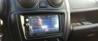
Mus viburnum 2 lux
Light control module (LCM) for VAZ 1118 Kalina norma
Light control module (LCM) for VAZ 1118 Kalina Lux
Light control module (LCM) VAZ 2170 Priora-2 with A
Light control module (LCM) VAZ 2170 Priora-2 Norma
Light control module (LCM) for VAZ 2170, 71, 72 Lada Priora (standard)
Light control module (LCM) for VAZ 2170, 71, 72 Lada Priora with PTF button (lux)
Light control module (LCM) VAZ 2190-2194 Lada Granta, Lada Kalina-2 (standard)
Light control module (LCM) VAZ 2190-2194 Lada Granta, Lada Kalina-2 (luxury)
Light control module (LCM) VAZ 2190-2194 Lada Granta, Lada Kalina-2 Lux with A
Headlight adjustment button (wheel) Vesta
This section presents (factory) lighting control units on VAZ vehicles.
Didn't find the product you were looking for.
I would like to thank the online store AVTOZAP63.RU. We ordered wheel hub caps for a cast R17 Lada Vesta SW Cross by Russian Post. The parcel was sent quickly, it arrived within a week. The product is well packaged, everything arrived intact. We are very pleased. Many thanks to the store AVTOZAP63.RU
Lyudmila Anatolyevna Vasenko 07/31/2019 18:49
Thanks for the parcel. We ordered electric lifts for a VAZ 2106. They arrived very quickly. Despite the fact that it was sent by Russian post, 5 days to Voronezh!! Thank you for your cooperation. I recommend the store
Irina 07/29/2019 08:51
Read all reviews
You can leave feedback to the store director on the website or by phone: +7 9277 899 597 Alexey
Lighting control modules MUS 50.3769, 521.3769, 522.3769, 58.3769, 582.3769 are designed for switching electrical control circuits for external lighting, front and rear fog lights, adjusting the level of illumination of controls and instruments, and controlling the angle of the light beam of automobile headlights.
Light control module Lada Granta FL (PTF and Autosvet, white backlight)
- RUB 1,950
- Description
- Characteristics
- Reviews (1)
- Question answer
Light control module for Lada Granta FL (with PTF and Autolight, white backlight). Suitable for Lada Granta, Kalina-2, Datsun.
Product characteristics
We recommend watching
Original standard windshield heating button with white backlight for Lada Granta FL. Suit..
Power window switch (button) Lada Granta FL (low-current, white backlight). Is ..
Original standard switch (button) for the ESP system of the Lada Granta FL (white...
Light control module Lada Granta FL (without PTF, white backlight). Suitable for Lada Granta, Cal..
Light control module Lada Granta FL (with PTF, white backlight). Suitable for Lada Granta, Kalin...
Original standard air conditioning button (switch) with white backlight for Lada Granta FL. Under..
Power window switch (button) Lada Granta FL (power, white backlight). Is anal..
Driver's door module Lada Granta FL Lux with white backlight, suitable for Lada Kalina, Kalina-2, Gr..
Lada Granta FL power window switch block (white backlight). Can be installed in Lada..
Switch block (window regulators and mirrors) Lada Granta FL (white backlight). Can be installed..
Switch (button) for heating the rear window of Lada Granta FL (white backlight). Suitable for Lada..
Diagrams of individual elements of electrical equipment of the Lada Granta
In addition to the main blocks, the album contains graphic images of individual elements, for example: door wiring harnesses; lighting control.
Right front door pinout
1 — block of the door wire bundle to the rear harness block;
2 — window lift electric motor drive;
3 - locking device;
4 — switch device for lowering and raising glass;
5 — block of the door cable bundle to the front right speaker.;
Left front door pinout
1 - similar to the right door;
2 — electric motor of the left door glass lifting device;
3 - door lock;
4 — power window switch block;
5 — output to the speaker of the left door.
Lada Granta rear door pinout
The pin locations are the same on the left and right rear doors.
1 — connecting block of the rear door wiring harness to the tailgate wiring block; 2 - to the loudspeaker; 3 - to the locking device.
Electrical circuit of the lighting control module
| Contact | Purpose |
| 2 | Rear foglights |
| 4 | To the daytime running lights |
| 30 | +12 V (from generator pin 30) |
| 31 | Frame |
| 56 | To low beam headlights |
| 58 | To side lights and backlight lamps |
| Xz | + 12 V (from pin 15 of the ignition switch) |
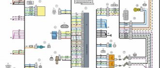
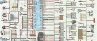
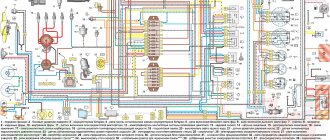
Schematic diagram of Lada Granta
The general map includes not only the front and rear of the car, but also the electrical circuit of the instrument cluster, as well as the ignition system.
Legend
The general connection map includes symbols, as well as serial numbers assigned to specific pantographs. All energy consumers are switched on the electrical wiring diagram into one large network using conditional lines. The latter are conductors, each of which is assigned a specific color for better clarity. All electrical circuits are assembled into bundles and connected to various modules using special connectors.
The cable marking includes two numbers:
- the first is a connector, terminal clamp or block to which a specific conductor is connected;
- the second is the contact number of the pantograph.
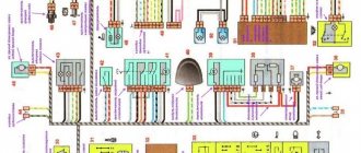
Diagram of the front of the car
- Right optical device (headlight).
- Electric motor for windshield washer system.
- Left external lighting fixture.
- Starter mechanism.
- Battery located in the engine compartment.
- Main mounting module with safety elements.
- Generator unit.
- Steering horn (horn).
- Connector for connecting to the instrument cluster.
- Another similar block.
- Connector for connecting to the dashboard.
- Electric motor for climate control fan.
- Electric fan of the power unit cooling system.
- ABS system hydraulic module.
- Speed controller mounted on the front right wheel.
- Speed sensor for front left wheel.
- Automatic transmission controller, if provided by the manufacturer.
- Transmission unit.
- Connector for connection to automatic transmission.
- Plug for connection to the gear selector.
- Output with connector going to the transmission speed controller.
- Air conditioning compressor.
Photo gallery: electrical circuits of the front part of the car
Colored Lada Granta connection maps:
Electrical connection diagram for electrical equipment in the rear of the car
- Connector for connecting the rear harness to the instrument cluster cables.
- A similar block designed for connection to the instrument panel.
- Right outer turn signal located on the side.
- Left side turning headlight.
- Parking brake state detection controller.
- Component of the rear window heating system.
- Lighting device in the car interior.
- A switch installed in the owner's seat belt.
- Luggage compartment lighting.
- Electric fuel pump module.
- Right rear light.
- Electric motor for the tailgate locking system.
- Switch for the lighting system in the car interior.
- Additional brake light.
- Left rear headlight.
- Connector for connecting the rear harness to the cables located in the rear left door.
- Block for connecting the rear harness with wires installed in the rear right door.
- Output for connecting the rear harness with electrical circuits located in the right door at the front.
- Connector for connecting the rear harness with a block of cables laid in the front left door.
- Control module of the airbag system.
- Output for connecting the rear harness with a connector for the rear number lamp cables.
- Another connector for connecting the rear block to the output of the instrument cluster.
- Speed controller mounted on the right rear wheel.
- Speed sensor located at the rear left.
- Driver's seat belt pre-tensioner.
- Pretensioner on the passenger side belt.
- Harness connector with cables for connecting to the instrument cluster.
Main characteristics of the electrical equipment of the Lada Granta car
Before you begin to study the electrical circuit, you need a clear understanding of the systems and all equipment of the car. It consists of the following:
- All systems are powered by a 12 volt battery, therefore no other voltages are permitted.
- To protect electrical networks in the car, blocks with safety elements and relays are installed. Often a car malfunction occurs due to a blown fuse. For example, if you cannot start the car, then this must be a faulty relay or a breakdown of the safety element of the fuel pump part.
- The main component of a car's electronic system is the engine control unit. Of course, if there are malfunctions in this system, the car’s engine will not start.
- All the most important electronic devices are connected via a terminal block and cable bundle to the instrument panel. If any icon remains on the dashboard after turning on the ignition and starting the engine, then there is a malfunction in the system.
- The engine control system (ECM) includes: controller (ECU); sensors monitoring engine parameters; executive modules. The ECU is located below the glove compartment, under the passenger's feet, namely under the floor covering. Its function includes: supplying voltage to sensors and actuators; control system diagnostics; troubleshooting and storing error codes.
Frequently encountered problems in the stable operation of electrical equipment:
- relay failure, fuse breakdown;
- corrosive deposits on connector contacts;
- fuse links burn out;
- failure of contacts in the terminal block.
A diagnostic device and a geographical image of the electrical connections of equipment and car systems will help to detect all damage.
Having an electrical circuit in the glove compartment, the driver will be able to fix a small malfunction on his own, this is especially true on a long journey. A knowledgeable driver, having studied the diagram of the required unit, represents the functional purpose of a particular circuit. However, we must remember that the electrical circuit of the Lada Granta equipment is quite complex for a person who is not related to technology. Therefore, in this case, if a malfunction is detected, you must contact specialists. In conclusion, a small reminder: electrical wiring cannot withstand large voltage drops in the on-board network. In other words, it is necessary to monitor the condition and state of charge of the battery.
Delivery by transport company
Delivery by one of the transport companies with a representative office in your city. Delivery time: 2-10 days depending on the distance of your locality from Togliatti. The most convenient and fastest way to deliver orders of different sizes. Delivery cost from 250 rub. depending on weight and delivery distance.
Orders are sent by transport companies based on 100% payment for the order. Dispatch by transport companies PEK, KIT, Baikal-Service is carried out on Wednesday, Thursday and Friday.
Where is the trunk limit switch of the Lada Granta Liftback
The trunk lid activation sensor is located on the left side, closer to the lamp. However, it is installed only in the “Lux” configuration. Rubber plugs are inserted into “Standard” and “Norma”.
In order to prevent sudden activation of the central locking and door locking, owners optionally install sensors. Considering the simplicity of the procedure, you can do this either independently or by contacting a service station for help from specialists. After installing the trunk end switch into the seat, we lay and connect the electrical wiring. “Plus” is powered from the side lights of the lamp, “minus” can be from the body or on the block with wires. Black with a white stripe is “minus”, red is “plus”.
In the Luxury package, the sensor is built into the trunk lid lock by default. When the lid is closed, the sensor automatically turns off the power from the light.