General diagram of electrical equipment of Lada Granta
1 - headlight; 2 — windshield wiper gear motor; 3 - generator; 4 - battery; 5 - snack; 6 — sound signal; 7 — fuse box in the engine compartment; 8 — power window switch for the right front door; 9 — motor-reducer for window lifter of the right front door; 10 — right front door connector; 11 — connection of cable blocks for connecting the front right speaker of the audio system; 12 — electric drive for locking the front right door lock; 13 — windshield washer pump; 14 — connection block to the ECU; 15 — electric fan of the engine cooling system; 16 — sensor of insufficient brake fluid level; 17 — left front door connector; 18 — central locking switch; 19 — interior lighting switch; 20 — connecting cable blocks for connecting the front left speaker of the audio system; 21 — right front door power window switch (installed on the driver’s door); 22 — power window switch of the left front door; 23 — front right door window lift motor gearbox: 24 — airbag control unit; 25 — electrical equipment control unit; 26 — instrument panel; 27 — mounting block; 28 — right direction indicator; 29 — brake signal switch; 30 — seat belt unfastened sensor: 31 — ignition switch (lock); 32 — lighting control unit; 33 — gear shift levers; 34 — left direction indicator; 35 — connection of cable blocks for connecting the rear left speaker of the audio system; 36 — electric drive for locking the rear left door; 37 — electric heater fan; 38 — additional heater resistance: 39 — heater switch: 40 — airbag module; 41 — hazard warning switch: 42 — trunk lock switch; 43 — rear window heating switch: 44 — pads for connecting the rear right speaker of the audio system; 45 — electric drive for locking the rear right door; 46 — reverse light switch; 47 — parking brake warning lamp switch; 48 — cigarette lighter; 49 — connecting cable blocks for connecting the main audio system unit: 50 — lighting on the cover of the center console of the instrument panel: 51 — electric power steering control unit; 52 — lampshade for interior lighting; 53 — rear light; 54 — trunk lid lock; 55 — license plate illumination; 56 — additional brake light; 57 — rear window heating element; 58 — luggage compartment lighting
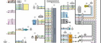
Instrument panel connection diagram
1-electrical panel block to the front wiring block; 2-harness block to the front harness block; 3-wire shield block to rear wiring block; 4-blocking the wiring of the electrical panel with blocking the rear wiring; control module for 5 headlights; block 6 ignitions; 7-on-board computer mode switch; 8-windshield wiper switch; 9-instrument panel; 10-light alarm switch; 11-switch of the trunk lock block; 12-block diagnostics; 13-instrument panel wiring lock to the air intake wiring lock; 14-rear window heating switch; 15 alarm switches; 16 brake light switch; 17-blocking the wiring of the instrument panel to the radio; 18-blocking the wiring of the instrument panel to the radio; 19 rotating devices; airbag module for 20 drivers; mounting block 22; electric power steering 23; 24 cigarette lighters; 25 heater control panel illumination lamps; 26-illuminator; 27-instrument panel wiring lock to the ignition system wiring lock; 28-controller; switch 29 clutch pedal position signal; electronic accelerator with 30 pedals; 31 additional resistor; electric motor 32 resistance; electric motor switch 33 heaters; 34-control unit for the door closing system.
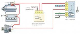
Relay: K1-relay for the electric fan of the engine cooling system; Relay K2 for blocking activation; K3-additional starting relay; K4-additional relay; K5-relay switch for direction indicators and alarm; Windshield wiper relay K6; Relay K7 for turning on the high beam; K8 - sound signal relay; Relay K9 for turning on low beam headlights; Relay K10 for turning on the heated rear window; K11-main relay; Fuel pump relay K12.
Rear Wiring Diagram
1-rear block of wires to the block of wires of the instrument panel; 2-blocking the rear wiring to the instrument panel wiring harness; turn signal 3-way right; turn signal 4-way left; 5 handbrake sensor; 6-element heated rear window; 7 ceiling lights for interior lighting; 8 switches in the driver's seat belt; 9-section lighting; 10-electric fuel pump module; 11 right lamp; 12 trunk locking motors; 13 interior lighting switches; 14-additional brake signal; 15 left lamp; 16-rear part harness block to left rear door harness block; 17-rear part harness block to right rear door harness block; 18-rear part harness block to right front door harness block; 19-rear part harness block to left front door harness block; 20 airbag control units; 21-rear part harness block to license plate light harness block.
Ignition system diagram Subsidies
1 oil pressure sensor warning lamp; 2-generator; 3-butterfly pipe with electric drive; 4 coolant temperature sensors; 5-ignition system wiring lock to instrument panel wiring lock; 6 solenoid valve for draining the adsorber; 7-speed sensor; 8 mass air flow sensor; 9 crankshaft position sensor; 10-oxygen concentration sensor; 11 controllers; 12 — diagnostic oxygen concentration sensor; ignition coil at 13; 14 candles; 15 nozzles; 16 blocks for wiring the ignition system and injector wiring; sensor for 17 shots.
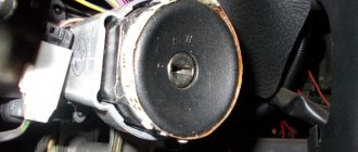
A malfunctioning ignition switch is a rare but annoying problem that requires replacement of the assembly or part of it. Replacing the ignition switch of a LADA Granta is quite feasible in a “garage” environment and does not require high plumbing skills or specialized equipment.
Malfunctions of the ignition switch LADA “Granta”
Ignition switch malfunctions can be divided into two types: electrical and mechanical. Electrical faults include the contact group of the lock, as a result of which individual energy consumers (most often the starter) stop working or the entire electrical system as a whole fails. This may also include a faulty vehicle immobilizer. Mechanical failures occur due to the breakdown of parts of the ignition switch or contact group, as well as physical wear of the contacts. This also applies to cases where, due to poor contact, the plastic parts of the contact assembly heat up and melt. Signs of a malfunction in the ignition switch of the LADA Grant:
- the key does not turn;
- turning the key does not turn on the ignition;
- the starter or other electrical devices do not work.
The last two signs do not necessarily indicate problems with the ignition switch, but they certainly appear when the contact group is not working properly.
To eliminate the malfunction, it is necessary to replace the LADA Granta ignition switch or part of it, for example, a group of contacts.
What is needed to replace the Granta ignition switch
To replace the ignition switch you will need:
- key to 10;
- a thin chisel and a hammer drill (or a drill with a drill for drilling screws with self-tapping screws);
- screwdriver;
- new LADA “Granta” ignition switch or contact group.
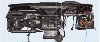
Detailed diagrams of nodes and blocks
1 — right headlight; 2 — electric motor for washers; 3 — left headlight; 4 — VAZ-2190 starter; 5 — rechargeable battery; 6 — main fuse block; 7 - generator; 8 — sound signal; 9, 10, 11 — front wiring harness blocks to the instrument panel wiring harness blocks; 12 — reverse lamp switch; 13 — electric fan of the engine cooling system.
1 – oil pressure warning lamp sensor; 2 – generator; 3 – throttle pipe with electric drive; 4 – coolant temperature sensor; 5 – ignition system wiring harness block to the instrument panel wiring harness block; 6 – solenoid valve for purge of the adsorber; 7 – speed sensor VAZ-2190; 8 – mass air flow sensor; 9 – crankshaft position sensor; 10 – oxygen concentration sensor; 11 – controller; 12 – diagnostic oxygen concentration sensor; 13 – ignition coils; 14 – spark plugs; 15 – Lada Granta injectors; 16 – blocks of the wiring harness of the ignition system and the wiring harness of the injectors; 17 – knock sensor.
Electrical diagram of the Lada Granta lighting control module
1, 2 – rear wiring harness blocks to the instrument panel wiring harness blocks; 3 – right side direction indicator; 4 – left side direction indicator; 5 – hand brake sensor; 6 – rear window heating element; 7 – interior lamp; 8 – switch in the driver’s seat belt; 9 – trunk lighting; 10 – electric fuel pump module; 11 – right lamp; 12 – trunk locking motor; 13 – interior lamp switch; 14 – additional brake signal; 15 — left lamp; 16 – rear wiring harness block to rear left door wiring harness block; 17 – rear wiring harness block to rear right door wiring harness block; 18 – rear wiring harness block to the front right door wiring harness block; 19 – rear wiring harness block to the front left door wiring harness block; 20 – airbag control unit; 21 – rear wiring harness block to the wiring harness block for license plate lights.
How to replace the ignition switch of a LADA Granta
The work can be carried out both indoors and outdoors. To avoid a short circuit, before removing the ignition key, it is necessary to disconnect the ground terminal from the Granta battery. The ignition switch of the LADA "Grant" is removed as follows:
- unscrew the five lower screws securing the steering column cover;
- unscrew the mounting bolts of the left and right casing;
- remove the lower part of the Granta steering column casing;
- remove the upper part of the casing;
- tighten the wire connector clamp attached to the ignition switch;
- disconnect the connector from the contacts of the Grant ignition switch;
- press the latch of the immobilizer antenna unit wire connector;
- disconnect the connector of the antenna unit of the LADA “Grant” immobilizer;
- using a thin chisel and hammer, unscrew and remove the screws securing the ignition switch to the steering column, or drill the bolts with a drill;
- remove the LADA Granta ignition switch from the steering column.
Tip: There is no need to change the lock group. It is cheaper to find the cause of the malfunction and simply replace a part, for example a group of contacts.
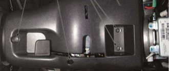
Where is terminal 30 located?
Here the side trim (2) in the driver's feet is unscrewed.
Arrows indicate mounting screws. Below it is a group of connectors (1). Under the side trim (1) on the passenger side next to the driver there is also a group of connectors (2). Arrows indicate mounting screws.
Right: The central switch unit (2) is located on the left under the instrument panel in the Audi A4. Above is the “13-place support for additional relays” (1).
Left: The illustration shows the placement of the central switch node sockets.
Standard terminal designations
The colorful mix of wires in a car is actually very well organized, since many parts of the car's electrical equipment are standardized. The numbers on various components and connecting elements of wires, as well as in electrical circuits on all German and some foreign cars have the same meaning:
Terminal 15 receives power only when the ignition is turned on from the ignition switch, while, along with the ignition/injection system, those consumers of electricity that should receive current only during operation of the vehicle are supplied with current. The wires to terminals 15 in most cases have a black sheath, sometimes with an additional colored stripe for certain current consumers.
Terminal 30 receives direct current from the battery positive or from the generator when the engine is running. If the tools are handled carelessly, this can lead to short circuits or cause sparks to rain if the wire connected to the battery negative is not removed. These wires, which are always live, are in most cases red, sometimes with additional colored stripes.
Terminal 49 refers to the intermittent and emergency light system.
Through terminal 53, voltage is supplied to the glass cleaning system.
From terminal 56, current is supplied to the low beam headlights through the yellow and yellow-black wires, as well as to the high beam headlights through the white and white-black wires.
Terminal 58 supplies power to the front parking lights, as well as the rear lights and license plate lights. The main color of the wire sheath is gray, sometimes with an additional colored stripe.
terminal 75 receives current when the ignition key is in the "On" position.
Terminal 31 is the ground terminal, through which the electrical consumer must be connected to ground in order to complete the electrical circuit. The corresponding wires have a brown sheath.
Labeled electrical connectors
In the Audi A4, individual wires are often bundled together in a black sheath, making it difficult to find a specific wire. In this case, orientation assistance is provided by multi-pin connections, which this chapter describes the exact number of wires and their exact location in electrical diagrams.
Terminal designation
Rate this post
Let's look at the main wires, or rather groups of wires, they are often called buses in electrical circuits, and they have standard symbols:
– Terminal “31” is the wires that are connected to the car body (ground)
– Terminal “50” is the wire, roughly speaking, that goes to the starter.
– Terminal “30” are wires on which +12 volts are always present, regardless of the position of the ignition switch, i.e. they are directly connected to the + (plus) terminal of the battery.
– Terminal “58a” supplies current to the front parking lights, rear lights and license plate lights.
– Terminal “75X” – on this bus +12 volts is present only in the “Ignition” position, but is absent at start, i.e. this is the case when +12 volts disappears from this bus in the “Starter” position
– Terminal “15a” is the wires on which +12 volts are present, in the “Ignition” position and the “Engine Start” position. The voltage from bus “15” powers the important parts of the engine, without which it will not start: spark plugs, ignition coil, various valves and the “brains” of the engine.
All of the above wires (except for ground “31”) go to the ignition switch.
Advice from experienced motorists and repairmen on the topic of where terminal 30 is located on the VAZ 2114 - you are welcome. All about renovation. Here we teach you how to repair a car yourself. How to repair a car yourself at home. We will help you with repairs and repair the car yourself. We know how to restore a car with minimal investment. I have attached video instructions.
Category: Car repair
Laughter on topic: It’s infuriating when you have to wake up your royal majesty at 6 a.m. on state affairs.
Published by Admin: at the request of Ilfat
Reviews from the car owner: Dad plays with his little daughter. Suddenly his daughter pushes him away and says: “Okay, that’s enough, I have a headache!” Dad looks at mom in bewilderment: “Is this what you’ve been taught since childhood, or what?”
Source
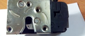
How to disassemble the ignition switch of a LADA Granta
To disassemble the ignition switch, follow these steps:
- bend the wire harness clamp on the Grant ignition switch connector housing;
- remove the terminals with wires from the housing;
- tighten the latches securing the plastic cover and remove it from the lock;
- press out a pair of plastic contact group clips;
- remove the contact block from the lock body.
After disassembling the lock, you need to check the condition of the contact group and terminals on the wires and clean them with fine sandpaper or replace them with new ones.
Assembling the ignition switch and installing it on the LADA “Grant” is carried out in the reverse order of disassembly and removal from the car.
P O P U L A R N O E:
Not all cars have a mains voltage monitoring system. Previously, domestic cars had a regular light in the dashboard indicating that the battery was charging. This is clearly not enough information. It would not be a bad idea to install an additional digital voltmeter or at least an indicator of several multi-colored LEDs showing the main thresholds of permissible voltages. Below are three simple car voltage LED circuits.
In some cases, you can independently diagnose a washing machine malfunction by reading the indicators on the front panel of the washing machine. The washing machine's fault code is displayed on the digital or LCD display. Next, we will take a closer look at the diagnostic codes of Indesit and Ariston washing machines.
Another charging scheme is very similar to the previous one, but differs in that it turns off after charging is complete. The charger is started by pressing the “start” button on the front panel; when supply voltage is applied to the circuit, relay K1 is activated and provides “self-capture”. Know more...
About the conventions
Let us remember that the practical Lada Granta model went into production back in 2011. This modern car is full of new modifications of complex instruments and electronic devices. All this aims to provide the driver with maximum driving comfort. Today VAZ produces the Lada Granta in three versions in terms of equipment:
The first two options have the same wiring diagram, but in the “Lux” it is different. It's a shame that the factory operating instructions for the car do not contain this wiring diagram. However, do not rush to get upset, because such an album with the entire list of schemes can be purchased in the market network of auto goods.
Electrical cabling involves the presence of a large number of bundles. The wiring diagram has symbols and serial numbers, each of which is assigned to a strictly specific pantograph. These consumers in the diagram are switched into the general network via conventional lines. To increase clarity, the developers used different colors for the lines. Next, the wires are assembled into bundles, which are connected to electrical units using special connectors.
The first number in the wire marking indicates the plug, connector or terminal to which this cable is connected. The number present behind the fraction sign indicates its correspondence to the contact number of the pantograph.
The reader can familiarize himself with the operating principle of a particular electronic unit on his own. If the defects are minor, then they do not create difficulties during the repair or replacement process. But the situation changes when a complex component fails, which implies the need to turn to electricians. To understand the situation with a malfunction of a specific pantograph, the owner of a LADA Granta does not need to remember all the details and details of the layout drawing, but it will be enough to know the location of the device and the features of the wiring leading to it.