Removing the instrument panel
We carry out work to replace the instrument panel, panel wiring harness and elements of the heating and ventilation system.
Disconnect the wire terminal from the negative terminal of the battery. Drain the liquid from the engine cooling system (see “Replacing the coolant”). In the engine compartment, remove the heating and ventilation system filter (see “Replacing the heating and ventilation system filter and cleaning the drainage hole in the plenum box”). Using a Phillips screwdriver, unscrew the four self-tapping screws that secure the filter housing of the heating and ventilation system to the instrument panel...
...and remove the casing. Loosen the clamps securing the heater inlet and outlet hoses...
...and remove the hoses from pipes 2 of the heater radiator. Using a high 10mm socket with an extension, unscrew nut 1 of the stud securing the flange of the heater radiator pipes to the front panel. Inside the car...
We disconnect the steering column from the instrument panel frame and lower it to the floor or remove the button completely (see “Removing the electric power steering column”).
We remove the seals of the openings of the right and left doors in the places where the instrument panel and the upholstery of the front pillars are installed.
Having overcome the resistance of the clamps, remove the left side trim of the instrument panel. Similarly, remove the right side trim of the instrument panel. Use a screwdriver to pry up the upholstery of the left front pillar and, overcoming the resistance of the pistons...
...remove the upholstery. Similarly, remove the upholstery of the right front pillar.
Remove the headlight beam direction control knob.
Using a 21mm socket, unscrew the nut securing the regulator to the instrument panel...
...and remove the nut.
We take out the headlight beam direction control from the hole in the instrument panel.
Using a screwdriver, press out the two latches on the glove box and remove the upper edge of the box from the instrument panel.
We open the glove box at a large angle and, applying the necessary force, pull the four split hinges of the box from their axes.
Near the opening of the left door, use a 10mm socket to unscrew the nut securing the tip of the “mass” wire... ...and remove it from the stud.
Using a 10mm socket, unscrew the two nuts securing the ends of the ground wires to the right bracket of the instrument panel console...
...and remove the wire ends from the studs.
Using a 13mm socket, unscrew the bolt securing the right bracket of the instrument panel console to the body bracket. Similarly, unscrew the bolt securing the left bracket of the instrument panel console to the body bracket.
Squeeze the two clips and disconnect the wiring harness block from the brake light switch.
By pressing the latch, disconnect the wiring harness block from the gas pedal module.
Disconnect the instrument panel wiring harness connector from the clutch pedal position sensor wiring harness connector.
On the right side of the instrument panel, by pressing the latch, disconnect one block of the wiring harness from the controller.
Using a screwdriver, move the pad clamps...
. disconnect the two wiring harness blocks from the fuse and relay mounting block.
Disconnect the two connectors of the front wiring harness of the engine compartment.
Using a 13mm socket, unscrew the two bolts securing the instrument panel frame to the front panel bracket (for clarity, the instrument panel trim has been removed).
The arrows show the bolts securing the instrument panel frame to the front panel bracket (for clarity, the instrument panel trim has been removed).
Using a 13mm socket, unscrew the two bolts on the left securing the instrument panel frame to the side panel bracket. Similarly, unscrew the two bolts of the right fastening of the instrument panel frame to the side panel bracket.
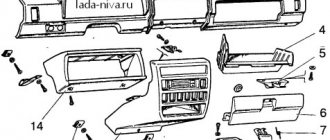
We take out the instrument panel complete with frame, heater and air ducts through the doorway. To remove the plastic trim of the instrument panel...
... use a Phillips screwdriver to unscrew the two screws under the instrument cluster. Under the cover of the mounting block...
Instrument panel assembled with frame and heater (view from the inside)
Front panel (instrument panel removed)
The numbers in the two photos show the connecting blocks of the wiring harnesses on the instrument panel and the front panel.
...use a Phillips screwdriver to unscrew the three screws on the left side...
...and one screw on the right side.
Using the same tool, unscrew the five screws on the right side of the instrument panel.
Under the central trim of the instrument panel, unscrew the two screws in the center...
...and one screw on top.
Using a Phillips screwdriver, unscrew the four self-tapping screws securing the heating and ventilation control unit to the instrument panel trim. Disconnect the wiring harness block from the cigarette lighter (see “Removing the cigarette lighter, replacing the backlight”).
We unscrew the two screws of the lower fastening of the instrument panel trim to the frame.
Using a Phillips screwdriver, unscrew the screw at the top left that secures the instrument panel trim to the frame. Similarly, unscrew the screw of the upper right fastening of the cladding.
Using a Phillips screwdriver, unscrew the two self-tapping screws securing the windshield defogger duct...
Using the same tool, unscrew the self-tapping screw securing the air duct of the right side deflector...
Unscrew the self-tapping screw securing the air duct of the left side deflector...
Remove the instrument panel trim from the frame. We install the instrument panel trim and the instrument panel assembled with the frame and heater in the reverse order. Fill in the coolant (see “Replacing the coolant”).
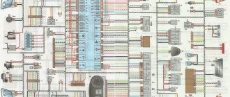
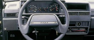
Principle of operation
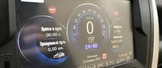
Manufacturers have equipped the car model in question with an electronic speedometer. Such a system calculates speed as accurately as possible with a minimum percentage of errors. The system consists of the following elements:
- The speedometer itself is a completely electronic device with a minimum number of mechanical parts. It works using signals received from the on-board computer.
- An on-board computer, a device necessary for calculating incoming data.
- A system of electrical wires that provide power to the speedometer components.
- A fuse is necessary to protect against electrical overloads and short circuits.
- Speed sensor, the main element of the system. It is used to calculate the speed characteristics while driving.
So, next we’ll look at how the whole system works. Its main element is the speed sensor or EMF. The device operates on the principle of a Hall ignition and distribution system. The EMF is installed on the gearbox near the flywheel. The flywheel has a special risk. When this risk passes by the EMF, the contact inside the sensor opens. This creates an electrical impulse. As the speed of the vehicle increases, the number of such “openings” increases, which means more pulse discharges are created.
The pulses are sent through the wire to the computer, where the number of signals per unit of time is automatically calculated. Secondary confirmation comes in the form of pulses from the crankshaft position sensor. The on-board computer transmits the received data to the receiver - the speedometer drive. Depending on the magnitude of the received signals, the drive deflects the instrument needle by a certain degree.
Removing the Lada Granta instrument panel
Tools:
- Open-end wrench 10 mm
- Ratchet wrench
- Extension
- 8 mm head
- 10 mm high head
- 13 mm head
- 21 mm head
- Torx T20 socket
- Medium Phillips screwdriver
- Large flat screwdriver
Parts and consumables:
- Technical capacity
- Coolant
Notes:
Carry out work if it is necessary to replace the instrument panel, panel wiring harness and elements of the heating and ventilation system.
1. Disconnect the wire terminal from the negative terminal of the battery.
2. Drain the engine cooling system as described in this article.
3. In the engine compartment, remove the heating and ventilation system filter as described here.
4. Using a Phillips screwdriver, unscrew the four self-tapping screws securing the heating and ventilation system filter casing to the instrument panel and remove the casing.
5. Loosen the clamps securing the heater inlet and outlet hoses and remove the hoses from pipes 2 of the heater radiator. Using a 10 mm high socket with an extension, unscrew nut 1 of the stud securing the flange of the heater radiator pipes to the front panel.
6. Inside the car, remove the mounting block cover as described in this article.
7. Remove the instrument cluster as described here.
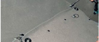
8. Remove the floor tunnel lining as described in this article.
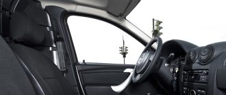
9. Disconnect the steering column from the instrument panel frame and lower it to the floor or remove the button completely, as described in this article.
10. Remove the instrument panel center trim as described here.
11. Remove the seals for the right and left door openings at the installation locations of the instrument panel and the A-pillar upholstery.
12. After overcoming the resistance of the clamps, remove the left side trim of the instrument panel.
13. Similarly, remove the right side trim of the instrument panel.
14. Use a screwdriver to pry up the upholstery of the left front pillar and, overcoming the resistance of the pistons, remove the upholstery.
15. Similarly, remove the right front pillar trim.
16. Remove the headlight beam adjustment knob by pulling it towards you.
17. Using a 21 mm socket, unscrew the nut securing the regulator to the instrument panel and remove the nut.
18. Remove the headlight beam adjustment control from the instrument panel hole.
19. Using a screwdriver, press out the two latches on the glove box and remove the top edge of the box from the instrument panel.
20. Open the glove box to a large angle and, applying the necessary force, pull the four split hinges of the box from their axes.
21. Near the opening of the left door, use a 10 mm socket to unscrew nut 1 securing the tip of the “mass” wire and remove it from the stud.
22. Using a 10 mm socket, unscrew the two nuts securing the ground wire lugs to the right bracket of the instrument panel console and remove the wire lugs from the studs.
23. Using a 13 mm socket, unscrew the bolt securing the right bracket of the instrument panel console to the body bracket.
24. Similarly, unscrew the bolt securing the left bracket of the instrument panel console to the body bracket.
25. Squeeze the two clips and disconnect the wiring harness connector from the brake light switch.
Lada Granta SPACE › Logbook › Shvi instrument panel
the penultimate stage of complete noise and vibration insulation of my grant, a panel with a motor shield.
in general, all the supporting units located on the panel were removed: the side plastic plugs (located at the ends), the central cover of the panel, under it the heater control unit was unscrewed, which is attached to two screws, the plastic steering wheel covers were also removed, the steering wheel itself (when removed, it is better mark the threads and the wheel itself in order to put it back straight) with an airbag (I had to ask an assistant because from the bottom from the sides to opposite each other you need to find two holes, insert objects such as nails or a screwdriver into them, press the clamps, while they are pressed, you need to pull off the airbag), these procedures must be carried out with the battery terminals removed, better than both and so that at least 1 minute has passed, otherwise the airbag will work,
there is also a plastic instrument panel cover behind the steering wheel (with three bolts and from the right corner it is held on a clip with an iron holder, you just need to pull it harder and it will come out),
also, under the trim, the instrument panel itself was removed (it is secured with four bolts, you also need to pull out the wiring harness from it that holds a valve-type mechanism that needs to be moved down), the headlight hydraulic corrector was removed (more precisely, its fastening, the twister is simply pulled off stupidly and under it the head screws on a nut like 19), the headlight control unit (unscrews with one self-tapping screw), the glove compartment was also removed (it is attached to the top with two bolts, then two plates from the top are pressed and it falls down, then you just need to pull it off from the lower mounts) there is still a space above the glove compartment I also twisted the plastic plate (attached with 4 screws) and removed the plug from the top of the panel on the passenger side (from the second sunroof type airbag) (forged with a knife and tore it out), the floor tunnel was also removed, all the removed elements were vibrated,
I sealed the outside of the glove compartment with vibrato, also put a layer of splen on the inside, and tightened the top of the inside with madeline so that nothing would rattle in the glove compartment.
In general, I’m quietly disassembling the panel, at one time I check with the book so as not to miss anything, I unscrewed all the screws on the outer panels, about 18 of them, and I’m thinking about what to do next, I look in the book and it says, carefully lift the panel and use a long screwdriver, unscrew the screws securing the air ducts of the front windows, and that’s it..., the book doesn’t explain in more detail how to unscrew these fucking screws so carefully, in general, I’m trying to lift this panel, but it didn’t work out that way, it doesn’t lift much, and it’s almost impossible to put your hand to these screws I couldn’t get it through, I went to the computer, sat down, started looking on the net for how to twist them, again a bummer, on the net the same book was paraphrased from different sources, in general I walked around this panel for a long time, this way and that and still with great difficulty and with a small tear I was able to stick my rather small hands in, on the right side from the bottom, from the side of the glove box, I crawled up to this screw, unscrewed it with a little difficulty, but on the left side I suffered and more than once remembered the designers who made such fastenings in the inside of the panel, and where finally It’s not really possible to crawl up, why the hell do I do that, I thought, and still, with difficulty, I stuck both hands through, stuck my left hand from the left side from the end where the side panel plug goes, lifting the panel to the top as much as I could, almost with a tear, stuck my right hand under the bend the air duct between it and the stiffening pipe where the speedometer wire block sticks out, in general I stuck my hands in almost with a bang, and in the end, with a little pain, I unscrewed this self-tapping screw. after which, with a little effort, the panel was removed, I did not remove the central air duct, and without removing it, the panel already began to come out and came out. I glued the panel itself with a thin 2mm vibrator, in the panel itself I noticed a feature that on the panel itself inside there is a tunnel for the air duct to the windshield, and it is made as a separate part and I assume that this design can rattle, so the joints between this trim and the panel itself I also glued the panel with vibration
I also vibrated the thin pipes of the air ducts and glued the joints with Madeline
Well, I think I’ve done the hardest thing (removed the panel) as soon as I start gluing, but it wasn’t there, a depressing picture opened up at the front door, it was that without removing the remaining units, i.e. the stove and the rest of the entrails will not get close to the engine shield, because the factory Shumka in the form of a carpet made of splenoid-like paralon was hanging (really hanging) between all these units and to remove it it was necessary to remove the rest of the entrails. I thought a little and again picked up this stolen book from the third Rome on a grant and take a bite out of you, not a damn thing is written in it about how to remove this stove and the rest of the guts, I looked through the whole book again and was convinced that the freeloaders did this booklet. since I scored a little because of the removal of the stove, because... there’s a radiator and pipes and antifreeze and all that stuff, and I really didn’t want me to disturb anything with my awkward movement before winter. I decided to rip off this Shumka surgically, partly because It was necessary to make noise anyway.
Removing the instrument panel
We carry out work to replace the instrument panel, panel wiring harness and elements of the heating and ventilation system. Disconnect the wire terminal from the negative terminal of the battery. Drain the liquid from the engine cooling system. In the engine compartment, remove the heating and ventilation system filter.
Using a Phillips screwdriver, unscrew the four self-tapping screws that secure the filter housing of the heating and ventilation system to the instrument panel...
...and remove the casing. Loosen the clamps securing the heater inlet and outlet hoses...
...and remove the hoses from pipes 2 of the heater radiator. Using a high 10mm socket with an extension, unscrew nut 1 of the stud securing the flange of the heater radiator pipes to the front panel. Inside the car...
...remove the cover of the mounting block.
We remove the instrument cluster.
Remove the floor tunnel lining.
We disconnect the steering column from the instrument panel frame and lower it to the floor or remove the button completely.
Remove the central trim of the instrument panel.
We remove the seals of the openings of the right and left doors in the places where the instrument panel and the upholstery of the front pillars are installed.
Having overcome the resistance of the clamps, remove the left side trim of the instrument panel. Similarly, remove the right side trim of the instrument panel. Use a screwdriver to pry up the upholstery of the left front pillar and, overcoming the resistance of the pistons...
...remove the upholstery. Similarly, remove the upholstery of the right front pillar.
Remove the headlight beam direction control knob.
Using a 21mm socket, unscrew the nut securing the regulator to the instrument panel...
...and remove the nut.
We take out the headlight beam direction control from the hole in the instrument panel.
Using a screwdriver, press out the two latches on the glove box and remove the upper edge of the box from the instrument panel.
We open the glove box at a large angle and, applying the necessary force, pull the four split hinges of the box from their axes.
Near the opening of the left door, use a 10mm socket to unscrew the nut securing the tip of the “mass” wire... ...and remove it from the stud.
Using a 10mm socket, unscrew the two nuts securing the ends of the ground wires to the right bracket of the instrument panel console...
...and remove the wire ends from the studs.
Using a 13mm socket, unscrew the bolt securing the right bracket of the instrument panel console to the body bracket. Similarly, unscrew the bolt securing the left bracket of the instrument panel console to the body bracket.
Squeeze the two clips and disconnect the wiring harness block from the brake light switch.
By pressing the latch, disconnect the wiring harness block from the gas pedal module.
Disconnect the instrument panel wiring harness connector from the clutch pedal position sensor wiring harness connector.
On the right side of the instrument panel, by pressing the latch, disconnect one block of the wiring harness from the controller.
Using a screwdriver, move the pad clamps...
. disconnect the two wiring harness blocks from the fuse and relay mounting block.
Disconnect the two connectors of the front wiring harness of the engine compartment.
Using a 13mm socket, unscrew the two bolts securing the instrument panel frame to the front panel bracket (for clarity, the instrument panel trim has been removed).
The arrows show the bolts securing the instrument panel frame to the front panel bracket (for clarity, the instrument panel trim has been removed).
Using a 13mm socket, unscrew the two bolts on the left securing the instrument panel frame to the side panel bracket. Similarly, unscrew the two bolts of the right fastening of the instrument panel frame to the side panel bracket.
We take out the instrument panel complete with frame, heater and air ducts through the doorway. To remove the plastic trim of the instrument panel...
... use a Phillips screwdriver to unscrew the two screws under the instrument cluster. Under the cover of the mounting block...
Instrument panel assembled with frame and heater (view from the inside)
Front panel (instrument panel removed)
The numbers in the two photos show the connecting blocks of the wiring harnesses on the instrument panel and the front panel.
...use a Phillips screwdriver to unscrew the three screws on the left side...
...and one screw on the right side.
Using the same tool, unscrew the five screws on the right side of the instrument panel.
Under the central trim of the instrument panel, unscrew the two screws in the center...
...and one screw on top.
Using a Phillips screwdriver, unscrew the four self-tapping screws securing the heating and ventilation control unit to the instrument panel trim. Disconnect the wiring harness block from the cigarette lighter.
We unscrew the two screws of the lower fastening of the instrument panel trim to the frame.
Using a Phillips screwdriver, unscrew the screw at the top left that secures the instrument panel trim to the frame. Similarly, unscrew the screw of the upper right fastening of the cladding.
Using a Phillips screwdriver, unscrew the two self-tapping screws securing the windshield defogger duct...
Using the same tool, unscrew the self-tapping screw securing the air duct of the right side deflector...
Unscrew the self-tapping screw securing the air duct of the left side deflector...
Remove the instrument panel trim from the frame. We install the instrument panel trim and the instrument panel assembled with the frame and heater in the reverse order. Fill in coolant.
How to remove the tidy on a Grant sedan and liftback
Removing the torpedo with your own hands on cars of the specified versions before and after 2013 is simple. To do this, you only need a Phillips and flathead screwdriver.
The sequence of actions looks like this.
- Initially, you should turn off the power to the car and place it in a stable position.
- Remove the cover of the interior fuse box.
- Next, you will need to find the mounting screw and unscrew it. The fasteners for the instrument panel trim are also unscrewed.
- Now the decorative trim can be removed and the mounting of the tidy itself can be exposed.
- There are two screws at the bottom of the console that hold it in place. The screws need to be unscrewed and the tidy lifted.
- Next, you should reach under the panel and remove the wire terminal block from its back.
Removing the front panel of Granta Lux
Before removing the center console, you will need to arm yourself with a plastic spatula or a flat-head screwdriver wrapped in electrical tape. You will also need to find several clips in case the standard ones are broken during disassembly.
- Turn off the power to the car - all manipulations with the device are performed only after disconnecting the battery.
- Using a plastic spatula or screwdriver, remove the radio/radio plug.
- Pull the heater and air duct controls towards you. The procedure must be performed with extreme caution. There is a risk of damaging the regulator.
- Next you will need to remove the facing plastic of the beard by prying it off with a screwdriver. The design contains plastic latches that are easy to break. During reassembly, new ones are put in their place.
- At the end, you will need to lift the tidy and disconnect the contact groups of wires from the reverse side.
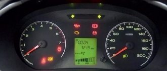
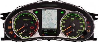
Which LEDs to choose for instrument panel illumination
To highlight the readings in the Granta or Kalina instrument cluster, green SMD-3528 LEDs are used. Instead, you can use SMD LEDs of different brightnesses. Here are the most commonly used:
- very bright SMD 5050 (luminous flux - 15 Lumens);
- bright SMD 3825 (brightness 7-9 Lumens)
- medium brightness SMD 3528 (about 5 Lumens);
- medium brightness SMD 3028 (about 5 Lumens);
- not bright SMD 3020 (about 4 Lumens);
- not bright SMD 3014 (about 3 Lumens).
The numbers after SMD mean the ratio of width and length, for example, an SMD 3528 LED has dimensions of 3.5 mm by 2.8 mm. You can buy everything you need on AliExpress (see catalog).
The approximate difference in LED brightness is shown in the photo:
Please note that using very bright LEDs to illuminate the instrument panel, reading readings in the dark may not be comfortable (they will dazzle). In this case, you can reduce the brightness by tinting the dashboard with a film (we select the light transmittance to taste). We recommend using SMD LEDs with a luminous flux of up to 5 Lumens for tuning the instrument panel.
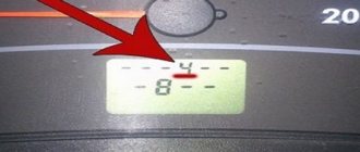
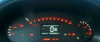
Symptoms
Car components rarely fail unexpectedly. Breakdowns are often preceded by various symptoms. There are also such cases when the speedometer breaks down. These include:
- Partial or complete failure of the arrow. The device stops showing data, freezes at a certain level, turns on periodically, and trembles.
- Complete failure of the instrument panel. The tachometer, odometer, and instrument lighting stop working.
- The error signal “P0500” appears. This code directly determines the speedometer error.
- The car loses power at the start, during acceleration.
- The power unit is difficult to start, stalls at low speeds, and is unstable when shifting into gear.
- Complete failure to ignite a flammable liquid while driving.
- High fuel consumption.
Symptoms of unstable operation of the power unit can be directly attributed to a breakdown of the speed sensor. It is on the basis of its data that the ECU controls fuel consumption for engine idle speed, and also maintains the balance of the amount of mixture while driving at different speeds. The following will describe in detail why the speedometer on the Grant does not work and the reasons for each breakdown.
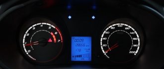
How to change the color of the instrument cluster illumination
1. Use SMD of the desired color. For example, use white LEDs to illuminate one part of the panel, and blue LEDs for the other.
2. Use a light filter (electrical tape or film of different colors) together with white LEDs. We stick it on the desired area, as a result of which we get the illumination of the desired color. To change the color, you do not need to use a soldering iron, just disassemble the instrument panel and stick a film of a different color.
It is worth noting that the hands have an orange coating. To change the illumination of the hands, wipe off the varnish with nail polish remover and, if necessary, apply a new varnish of a suitable color. Another option is to use LEDs for the arrows of the desired color.
You can change the backlight of the screen (display) not only by replacing its LEDs, but also by turning the film over. First, we tear off the film from the display, clean the remaining adhesive with a solvent and glue the film on the back side. This results in an inversion of the panel display:
3. Use RGB-SMD LEDs. If you want to change the backlight color at once. In this case, you will have to additionally output switching control.
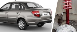
Signs of a malfunctioning speed sensor
Malfunctions of the Lada Granta speed sensor are associated with its location near the road surface, which causes intense exposure to water, dirt, sand and reagents that are sprinkled on roads in winter. Speed sensor malfunctions manifest themselves as follows:
- when driving, the speedometer needle does not deviate from the initial mark or works only periodically;
- the speedometer readings are very different from the actual speed;
- the engine is idling unsteadily;
- engine thrust decreases;
- fuel consumption increases.
Do-it-yourself dashboard overexposure
You will need: remove and disassemble the instrument cluster, SMD LEDs (unsoldered from LED strip or LED lamp), soldering iron.
The process of replacing LEDs on the instrument panel board consists of unsoldering the standard SMD LED and soldering a new one in its place. During such tuning, there are several important points to consider:
- take your time so as not to damage the conductive traces of the board;
- observe the polarity (SMD LEDs have a bevel on one side, install a new LED in the same position);
- do not overheat the LEDs; high temperatures may cause them to fail;
After soldering the required LEDs, it is recommended to check the backlight. To connect the instrument cluster at home, you need to apply +12V to pins 19 and 21, and ground to 17. You can also verify that the installed LEDs are working properly using a multimeter in “tester” mode, connecting the probes to the LED according to the polarity (red probe is plus) :
If all LEDs are installed successfully, reassemble in the reverse order. Relighting the instrument cluster of Grants or Kalinas is a great way to make your car more individual and stylish. It is noteworthy that there are a lot of options for implementing such panel tuning, but which style suits you best? Participate in the survey, share video materials and photos of your improvements.
Let us remind you that the website presents other modifications to the instrument panel, for example, you can reflash it and install an outside air temperature sensor.