Don’t ask me anything, I wrote everything I know.
You can copy this article to your blog, then notify me so that I can delete this entry.
First type of devices:
Kalinas and Prioras without can tires.
On the VAZ-1118 (Kalina) from 2004 to 2011, the device was installed 1118-3801010
All these devices have a 32-pin connector. You can, for example, install a Priorovskaya tidy instead of a Kalinovskaya one, but it is advisable to select the desired model (1118 or 2170).
Instead of such a tidy, you can install an expensive tidy with navigation 1118-3801010-50 for Kalina and 2112 with Europanel or 2170-3801010-50 s for Prior produced before July 2012 (without CAN bus). And they additionally need a GPS antenna and a wiper switch with a joystick (they are described below).
Addition from Shurik5891
On the first releases of 1118 devices, there are no LEDs for ABS, ESD, or seat belts.
Addition from Shandys
On Kalina1 2013
with e-gas and cable drive gearbox there is a tidy 11180-3801010-20 vdo _____________________________________ Second type of
Grant devices of the 1st generation
Granta appeared in 2011
From a smart book: “The electronic engine control system of the LADA GRANTA car implements a data exchange interface between the ECM, instrument cluster and diagnostic device via the CAN bus. The CAN bus is a two-wire line: - CAN L low level line (contact “X2/D2” of the ECM - contact “7” of the instrument cluster - contact “14” of the diagnostic block); - CAN H high level line (contact “X2/F1” of the ECM – contact “8” of the instrument cluster – contact “6” of the diagnostic block). The immobilizer is integrated into the instrument cluster." Pinout of devices 2190
: 1 - To the emergency oil pressure sensor, 2 - To the parking brake switch, 3 - Service. Panel diagnostics, 4 — To the exterior lighting switch, 5 — To the right turn signal switch, 6 — To the left turn signal switch, 7 — CAN-L, 8 — CAN-H, 9 — To the seat belt sensor, 10 — “RESET” key » on the steering column switch, 11 - To the brake fluid level sensor, 12 - To the high beam headlights, 13 - To the low beam headlights, 14 - To the rear fog lamp, 15 - To the front fog lamps, 16 - Immobilizer antenna input (b) , 17 — “Ground” panel, 18 — Immobilizer antenna input (a), 19 — To terminal “30,” 20 — To electric power steering, 21 — To terminal “15,” 22 — To door sensor, 23 — MK key “ forward", 24 - MK key "back", 25 - To the outside temperature sensor, 26 - To the fuel level sensor. Instrument clusters are interchangeable.
Pinout provided by fellow teemest
The connector for these devices is 26-pin.
Some devices have sound for turn signals and/or hazard lights, some do not. This is normal and is not a malfunction. Instead of a temperature indicator, there was only a light bulb, the lighting of which indicated overheating. On June 16, 2014, they began installing the device with firmware 092, and in the window it was possible to select engine temperature readings. On cars with the standard configuration, there is no outside temperature sensor. If the device has firmware 090, you can take sensor 2115-3828210, one contact to the body, the second to contact 25 of the devices, and the function of displaying the outside temperature will work. Devices may also differ in the presence/absence of an indicator for front fog lights, an indicator for an automatic transmission, etc. And there are these same devices with navigation.
A detailed article on flashing such devices is here www.drive2.ru/l/6010764/
The third type of devices
Priora 1 with can-bus.
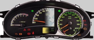
Since July 2012, Priora also began installing devices with a CAN bus. For example, 2170-3801010-30 Addition from turbomotor412
Pinout of CAN panel Priora 1st generation 2170-3801010-30. 1) To the electric power steering, 2) Reserve, 3) Reserve, 4) To the parking brake switch, 5) To the immobilizer control unit (electrical package), 6) Reserve, 7) To the light control module (light on indicator), To the switch turn signal (right side), 9) To the turn switch (left side), 10) CAN_L, 11) CAN_H, 12) Immobilizer antenna (not engaged), 13) Immobilizer antenna (not engaged), 14) To the steering column switch (" button Reset"), 15) To the brake fluid level sensor, 16) Reserve, 17) To the high beam switch, 18) To the light control module (light dimmer), 19) Housing, 20) Terminal “30” of the battery, 21) Terminal “15” of the ignition switch, 22) Reserve, 23) To the steering column switch (down button), 24) To the steering column switch (up button), 25) To the outside temperature sensor, 26) To the outside temperature sensor, 27) To the fuel level sensor, 28) Reserve, 29) Reserve, 30) Reserve, 31) Service. Diagnostics of instrument cluster during production, 32) Reserve
On these devices, the built-in immobilizer is not used, but the immobilizer of the electrical package unit is used, with which the ECU communicates via the k-line. ECU Bosch ME 17.9.7 21126-1411020-45 transitional. Supports both CAN-bus (communication with ABS 9.0, dashboard, airbag unit) and k-line (communication with the immobilizer in the electrical package unit).
The connection pins also change: 2) To the radio receiver “MUTE”, 10) Reserve, 11) To the radio receiver “AUDIO OUT” “-“, 14) To the steering column switch (“Left”, “OK”), 23) To the steering column switch ( “Down”, “Menu”), 24) To the steering column switch (“Right”, “Up”), 25) To the radio receiver “AUDIO OUT” “+”, 28) CAN_L, 29) CAN_H photo of the 2012 Priora connector
Both of these devices potentially support the indication of the ESP system, although in fact no such cars left the assembly line. 2170-3801010-30 has an icon to the left of the screen, and 2170-3801010-60 on the LCD screen.
The fourth type of devices
With can-bus for Priora-2 Pinout of Priora-2 devices: 1 - EUR, 4 - handbrake, 7 - dimensions, 10 - CAN H, 11 - CAN L, 12 and 13 - immobilizer antenna, 14 and 23 and 24 - k steering column switch, 15 — brake reservoir, 18 — backlight, 19 — ground, 20 — constant power, 21 — ignition, 25 and 26 — outside temperature sensor, 27 — fuel level, (28 and 29 — CAN bus for devices with navigation) , 31 - diagnostics.
That is, devices for with a CAN bus, for the Priora-1 generation and another for the Priora-2 generation.
Additions from Oren56ru
: — Since June 2012, the Priora Coupe came with a CAN bus and already began installing devices with navigation. — link to hardware improvements for devices with navigation and Amoled display if it freezes www.drive2.ru/c/2282291/
Lada Largus instrument panel pinout
Lada Priora instrument panel pinout
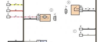
Instrument panel wiring harness connection diagram:
No. Connection of the Itelma gearbox with navigation without CAN 1 To the electric power steering 2 MUTE 3 To the oil pressure sensor 4 Parking brake switch 5 To the immobilizer control unit (electrical package) 6 To the airbag control unit 7 To the light control module (light on indicator) 8 Turn signal switch (right side) 9 Turn signal switch (left side) 10 To the engine control system unit 11 AUDIO OUT - “Battery” 12 To the seat belt sensor 13 To the ABS unit (EBD malfunction) 14 Steering column switch “Buttons” 15 Brake fluid level sensor 16 To the ABS unit (ABS malfunction) 17 To the high beam switch 18 To the light control module (scale lighting regulator) 19 Housing 20 Terminal “30” of the battery 21 Terminal “15” of the ignition switch 22 To the control unit (signal fuel consumption) 23 To the steering column switch “UP” 24 To the steering column switch “DOWN” 25 To the radio receiver “AUDIO OUT “+” 26 To the outside temperature sensor 27 To the fuel level sensor 28 To the speed sensor 29 To the coolant temperature sensor. liquid 30 To control unit engine (tachometer signal) 31 Service diagnostics 32 To terminal “L” of the generator relay regulator
Pinout of the Lada Priora instrument panel with CAN bus
Lada Kalina instrument panel pinout
Pinout of the instrument panel Lada Kalina 1
Pinout of the instrument panel Lada Kalina 2
Lada Granta instrument panel pinout
Lada Granta instrument panel pinout
Lada Granta instrument panel pinout
Connection diagram of the instrument panel wiring harness on a Lada Granta VAZ 2190:
1, 2 — connectors of the instrument panel wiring harness to the connectors of the front wiring harness; 3, 4 — connectors of the instrument panel wiring harness to the connectors of the rear wiring harness; 5 — external lighting control unit; 6 — ignition switch; 7 — on-board computer mode switch; 8 — glass cleaner and washer switch; 9 — instrument cluster; 10 — switch for direction indicators and headlights; 11 — trunk lock drive switch; 12 — diagnostic connector; 13 — connector of the instrument panel wiring harness to the connector of the wiring harness of the air supply box; 14 — rear window heating switch; 15 — alarm switch; 16 — brake light switch; 17, 18 — connectors of the instrument panel wiring harness to the head unit and audio device; 19 — driver airbag contact ring; 20 — driver airbag module; 21 — mounting block connector; 22 — mounting block; 23 — electric power steering; 24 — cigarette lighter; 25 — backlight lamp for the heater control unit; 26 — backlight lamp; 27 — connector of the instrument panel wiring harness to the connector of the ignition system wiring harness; 28 - controller; 29 — clutch pedal position sensor; 30 — electronic accelerator pedal; 31 — additional resistor; 32 — heater electric motor; 33 — heater motor switch; 34 — control unit for the door lock system; K1 - relay for the electric fan of the engine cooling system; K2 - door lock relay; K3 - additional starter relay; K4 - additional relay; K5 - relay-interrupter for direction indicators and hazard warning lights; K6 - windshield wiper relay; K7 - headlight high beam relay; K8 - sound signal relay; K9 - relay for low beam headlights; K10 — relay for turning on the heated rear window; K11 - main relay; K12 - fuel pump relay.
Lada Largus instrument panel pinout
Lada Largus instrument panel pinout
Lada Largus instrument panel pinout
Source
Which wire goes where?
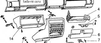
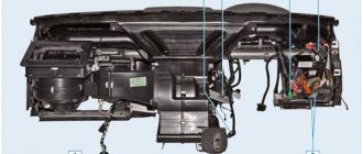
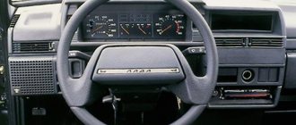
First, let's look at the back of the instrument panel. At the top there are:
- fuel level indicator;
- dashboard lighting lamps;
- control of right and left turns (separately);
- tachometer;
- block with many plugs;
- coolant temperature gauge.
As you can see, there is really nothing particularly complicated here. At the bottom of the instrument panel on the back side there are controllers:
- high beam;
- "emergency lights";
- CHECK ENGINE;
- battery charge;
- parking brake;
- oil pressure;
- air damper (for models with a carburetor);
- outdoor lighting work.
In addition, there is also a speedometer and a brake fluid level indicator lamp.
Now let's take a closer look at the pads. There are two of them - white and red. In the first, the connectors and wires look like this (in order):
- Ground wire black.
- Red-brown – low-voltage supply from the ECU to the tachometer.
- Yellow – high-voltage supply to the tachometer from the coil.
- Red-blue - comes from the battery through the 6th fuse Const with a voltage of 12 volts.
- Green-white - leads to the coolant temperature sensor.
- Green-yellow – fuse F1, responsible for the side lights.
- This connector has no color, it goes to the throttle valve.
- Red and white – leading to the CHECK ENGINE indicator light.
- 2 orange wires leading to two F19 + 12 volt power fuses.
- Same as the previous connector.
- 2 blue-brown wires leading to the “VK” terminal of the handbrake.
- The output to terminal D of the generator is a brown-white wire.
- Gray and blue - wire going to the oil pressure sensor.
Scheme of Lada Kalina VAZ-1117, VAZ-1118, VAZ-1119
Complete information on the electrical equipment of the Lada Kalina car, including the following modifications: VAZ 1118 - 5-door sedan (2004 to 2011), VAZ 1119 - hatchback (since 2006) and VAZ 1117 - station wagon. Also reviewed is the Lada Kalina Sport, a sporty version of the hatchback produced since 2008. There are diagrams of all blocks, including the location of relays and fuses, which allows you to carry out minor repairs of auto electronics and replace burnt-out elements yourself. At the end of the reference book there is a link to a PDF album of schemes.
General diagram of VAZ-1117, VAZ-1118, VAZ-1119
1 – right headlight; 2 – engine compartment lamp switch; 3 – sound signal, 4 – Lada Kalina starter; 5 – battery; 6 – generator; 7 – windshield wiper electric motor; 8 – left headlight; 9 – power window switch of the right front door (passenger]; 10 – power window motor of the right front door; 11 – right front door lock; 12 – connection block to the right front column; 13 – windshield washer motor; 14 – air temperature sensor; 15 – connection block to the injection system wiring harness; 16 – left front door lock; 17 – brake fluid level sensor; 18 – connection block to the left front column; 19 – right front door power window switch (driver); 20 – left front door power window switch; 21 – door lock switch in the switch block; 22 – electric window motor of the right front door; 23 – mounting block; 24 – immobilizer; 25 – power accessories control unit; 26 – instrument cluster; 27 – right side turn signal; 28 – glove compartment lighting lamp ; 29 – glove compartment lamp switch; 30 – brake light switch; 31 – ignition switch; 32 – lighting control module; 33 – steering column switch; 34 – left side direction indicator; 35 – connection block to the right rear column; 36 – rear door lock; 37 – rear window heating switch; 38 – reverse lock switch; 39 – alarm switch; 40 – heater motor switch; 41 – additional resistor; 42 – heater electric motor; 43 – block is connected to the left rear column; 44 – electric fuel pump with fuel level sensor; 45 – reverse lamp switch; 46 – handbrake sensor; 47 – cigarette lighter; 48 – reverse lock; 49 – connection block to the radio device; 50 – backlight lamps for heater control levers; 51 – Kalina illuminator; 52 – control unit for electromechanical power steering; 53 – interior lighting unit; 54 – right rear light; 55 – trunk locking motor; 56 – switch in the trunk lock; 57 – license plate lights; 58 – additional brake signal; 59 – rear window heating element; 60 – trunk lighting; 61 – left rear light
Elements of the instrument panel harness connection diagram
1, 3, 4, 5 — blocks of the tidy wire bundle to the front harness; 2, 8 - the same for the rear “pigtail” of wires; 6, 7, 9, 10 - continuation of the direction to the assembly unit; 11 — power supply for the lighting control device; 12 — set of instruments; 13 — toggle switch for the electric motor of the stove; 14 — power supply to the air supply box; 15 — ignition switch Lada Kalina; 16 — immobilizer block; 17 — block of the dashboard wiring harness to the ignition system wire bundle; 18 — cigarette lighter power supply; 19 — alarm switch; 20 — rear window heating switch; 21 — brake light switch; 22 — alarm light breaker; 23 — adjustment of computer modes ; 24 — windshield wiper control; 25 — VAZ horn switch ; 26, 27 — heating and ventilation control lighting lamps; 28 — glove box lighting; 29 — power supply to the on/off button in the glove compartment; 30, 31 — pinout for the standard radio; 32 — power supply to the electric motor of the stove; 33 — heater resistor network; 34 - electric amplifier control unit.
Features of connecting BC
In conclusion, I would like to dwell in more detail on such a point as installing an on-board computer. In the typical pinout diagram shown just above, there is only one wire leading to it - brown. But for the correct operation of this device, this alone will not be enough. Therefore, here is a complete pinout diagram for connecting the on-board computer:
- Green wire – comes from the electronic control unit, needed to obtain information about fuel consumption.
- Orange – goes to the ignition switch, to terminal 15.
- White-red - in the same place, only to terminal 30.
- The common ground wire is black.
- Brown – needed to take speed data.
- Red-green - to the positive circuit of the fuel level sensor.
- White - leads to the light control, which is responsible for the lamps that illuminate the instrument panel.
Detailed electrical diagrams of car components
Instrument panel wiring harness wiring diagram
1,2,3,4 blocks of the instrument panel wiring harness to the rear wiring harness blocks; 5,6 blocks of the instrument panel wiring harness to the blocks of the front wiring harness; 7 block of the instrument panel wiring harness to the block of the wiring harness of the air supply box; 8 block of the instrument panel wiring harness to the block of the front wiring harness; 9 lighting control module; 10 ignition switch; 11 on-board computer mode switch; 12 windshield wiper switch; 13 horn switch; 14 light signaling switch; 15 instrument cluster; 16 evaporator temperature sensor; 17 interior air temperature sensor; 18 air conditioner switch; 19 controller of the automatic climate control system; 20 heater damper gearmotor; 21 rear window heating switches; 22 alarm switch; 23 brake signal switch; 24 cigarette lighter; 25 electric power steering control unit; 26,27 connectors for the instrument panel wiring harness to the radio; 28 backlight lamp for the heater control panel; 29 lighting Lada Kalina; 30 mounting block: K3 additional starter relay; K4 additional relay; K5 relay breaker for direction indicators and hazard warning lights; K6 wiper relay; K7 relay for high beam headlights; K8 horn relay; K9 relay for turning on fog lights; K10 relay for turning on the heated rear window; K11 electric seat heating relay; K12 air conditioning compressor clutch activation relay; 31 heater motor switch; 32 electric heater motor; 33 additional resistance of the heater electric motor; 34 glove box lighting; 35 glove box lighting switch; 36 control unit of the automobile anti-theft system APS6; 37 driver airbag module; 38 passenger airbag module; 39,40 the instrument panel wiring harness blocks to the ignition system wiring harness blocks.