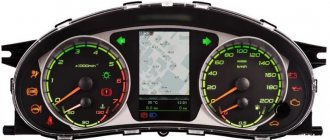
VAZ has noticeably improved the instrument panel of Lada Priora cars in comparison with earlier models that were produced at the plant. When developing the new dashboard, Soft Look plastic was used, similar to high-grade leather material. In addition, it is quite durable and difficult to scratch.
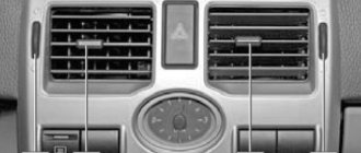
In addition to the instrument panel, such plastic was used on the upper part of the doors. The luxury Lada Priora contains several parts on the dashboard that are varnished black. In addition, Priora is equipped with a GLONASS-GPS navigator with a large color touch screen, which displays navigation-related information necessary for the driver, for example: route system configuration, connection with navigation, audio system interface, etc.
Navigation is controlled using the steering column switch on the right. During reviews of a domestic car, most experts mention that the Priora’s built-in computer is well adapted to the local population, because all information displayed on the display is displayed in the native Russian language.
GLONASS-GPS supports 83 regions of Russia and contains a complete map of their roads, on which about 300,000 objects are marked (gas stations, hotels, cafes, restaurants, shops, car services). The maps show all the routes in sufficient detail, down to the house numbers.
What does the dashboard consist of?
The Priora instrument panel contains all the necessary parts that no modern car can do without:
- regulator of external lighting and internal panel lighting;
- switch for turning, side and headlights;
- signal regulator;
- car instrument cluster;
- windshield wiper and washer regulator.
This is how the dashboard works
In addition, the panel contains an ignition switch connected to the anti-theft system. It contains 3 positions. Among the secondary mechanisms, we can note the presence of regulators for the rear window heating system, alarm and interior cooling. It is also worth mentioning the glove compartment, built-in clock and radio input jack.
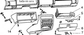
Sometimes a certain panel element becomes unusable and you have to look for ways to replace it. In this case, you will need to disassemble the interior. Below is how to disassemble the instrument panel.
Rear door wiring harness diagram Kalina 2
1 – contacts of the tailgate wiring harness to the rear wiring harness block; 2 – block of the wiring harness of the rear additional (tailgate) to the block of the wiring harness of the license plate lights; 3 – gear motor for the electric drive of the tailgate lock; 4 – rear window heating element; 5 – rear window wiper gear motor; 6 – tailgate lock; 7 – contacts of the tailgate wiring harness to the rear wiring harness block 2; 8 – additional brake signal.
How to disassemble the instrument panel?
It often becomes necessary to dismantle the car interior in order to replace a part, for example, backlight bulbs. To do this, first of all, you need to understand how to disassemble the instrument panel. Removing the panel is quite simple. Select the required screwdriver and carefully unscrew the attached hardware.
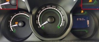
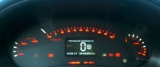
Disassembling the panel begins with removing the hands on the dial, which can be disconnected with a knife. The main thing is to be careful and not damage the speedometer parts. It is advisable to use cardboard as a holder for glass elements. Replacing the backlight is done by scraping out the cover of the gasket in the speedometer. If you do not need to change the backlight of the sensors, you can simply clean them and leave them brighter.
But in most cases, the driver wants to change the color of some elements in the speedometer and make it much more useful. For example, the backlight of the instrument panel will be able to display the maximum permissible speed or extremely high engine overheating with indicators of a different color. To do this you will need a thin multi-colored cellophane bag.
You need to use a small piece of brightly colored cellophane to cover the indicator you are interested in on the inside of the dial. Dashboard lighting is limited to more than just highlighting indicators. Many motorists try to ensure that the lighting of their devices is uniform.
To achieve brighter and more even illumination, it is necessary to cover the panel with a special LED strip, which must be connected to the stock backlight wires in accordance with all the rules of current resistance. The set of instruments on the Priora can be easily supplemented with the latest method of illuminating the needles.
You can use CMD diodes, which can be easily fused into the glass panel using a soldering iron. To do this, we disassemble the dial and begin soldering directly under the base of the hands. The contact wires must be connected from the reverse side. If the instrument panel in Priora is broken, qualified assistance may be needed to repair it.
But you can easily do it yourself. To do this, you will need a panel pinout, that is, a diagram indicating the correspondence of the contacts with certain car devices. It looks like this:
- 1 — power steering;
- 4 - hand brake;
- 7 — external lighting regulator;
- 8 — right turn signal;
- 9 — left turn signal;
- 12,13 — immobilizer antenna sockets (A and B);
- 14 — mileage reset regulator;
- 15 — brake fluid regulator;
- 18 — instrument panel backlight control;
- 20 — battery terminal 30;
- 21 — battery terminal 15;
- 23,24 — forward and backward buttons on the steering column;
- 25,26 — outside temperature regulators (- / +);
- 27 — fuel tank regulator;
- 31 - panel diagnostic service.
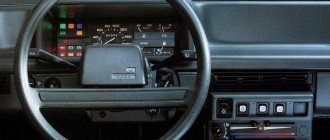
How to remove the console on a Lada Priora?
Removing the console is a simple and straightforward process, but there are a few things you need to know. For example, under the Open cover there are 2 screws. In addition, you will find 4 more screws under the ashtray and radio. They all serve as mounts for the console, so you need to unscrew them.
Pull the cover towards you and disconnect the nozzles from the stove. After this, disconnect the heating system, clock and control system by hand. The console can now be pulled out with a slight movement. Often the console on the Priora begins to creak, and it becomes necessary to eliminate this unpleasant sound.
First you need to remove the facing panel and cover its edges with a special sound insulator, for example, madeleine. It is also necessary to treat all areas that the console touches and make sure that it will not rattle after assembly.
What is a CAN bus?
This is one of the many electronic devices in the car. It is entrusted with the task of combining various sensors and processors into a single system with synchronization. The bus ensures the collection and exchange of information that is necessary to correct the operation of vehicle systems and components. CAN is short for Controller Area Network. Therefore, the bus is a kind of “road” for transmitting information from the controller to devices and vice versa. This standard was developed and implemented more than three decades ago. Today it is used not only in cars, but also in industry, including in smart homes.
Do-it-yourself dashboard tuning on Priora
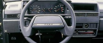
Torpedo of a Lada Priora car
The dashboard on the Lada Priora has improved characteristics compared to previous models of the domestic automobile industry. When creating it, “soft look” class plastic was used, which looks like good leather and is scratch-resistant. The same material, in addition to the dashboard, is on the upper trims of the door trims. The new Lada instrument panel in the “luxury” configuration may have a number of parts decorated with black varnish.
The panel on the Priora has a large display with touch control, which displays auxiliary and external information, in particular: the navigation screen, settings from the multimedia system, parameters from the trip computer, etc. Experts note that the instrument panel computer is maximally adapted for Russian users, i.e. - information is transmitted in Russian.
What is a CAN bus in a car?
CAN in relation to a car can be called a “spine” to which all electrical devices are connected. The signals are digital, and the conductors to each controller are connected in parallel. Thanks to this, high network performance is achieved.
In modern cars, sensors from the following devices are combined into a single network:
- Motor;
- Gear box;
- Airbags (airbags);
- Anti-lock braking system;
- Power steering;
- Ignition;
- Dashboard;
- Tires (controllers that determine the pressure level);
- Wipers on the windshield;
- Multimedia system;
- Navigation (GLONASS, GPS);
- On-board computer.
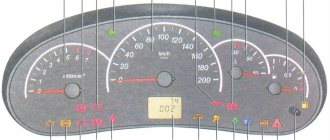
Description of the dashboard
The dashboard contains the following elements:
- Unit for controlling instrument lighting and external lighting.
- Horn switch.
- Switch for turn signals and headlights.
- Instrument cluster for Lada Priora.
- Lever for glass washer and wiper.
There is also an ignition switch on the instrument panel, which is combined with an anti-theft device. On the Lada Priora it has three positions. In addition, the instrument panel contains buttons and mechanisms such as a heated switch on the rear window, a clock, an alarm switch, a glove box lid, a tape recorder socket, an ashtray, a fan control unit, etc.
Tuning for the dashboard (dashboard) can be done with your own hands if you want to change the lighting for the instruments. In this case, the panel must be removed. The answer to the question: “How to remove the panel?” quite simple - using a screwdriver. Then we unscrew the fastening screws, disassemble the panel, remove the hands (you can use a knife, placing a piece of cardboard on the dial), and separate the cover from the plexiglass.
Replacing the dashboard backlight is done by scraping off (with a knife) the coating on the gasket numbers. If you want to leave them white (brighter), then you can put all the elements back together. However, many drivers want to make the instrument panel more informative. To do this, take a not very thick plastic bag with colored designs, from which parts of a certain color are cut out and glued to the back of the instrument panel. This way you can highlight, for example, areas of high speed on the speedometer, or “cold” areas on the temperature scale.
Development of a sniffer and study of the CAN bus protocol
After I have access to listen to the CAN bus, I need to decipher who is transmitting what to whom. The CAN packet format is shown in the figure.
All utilities from the can-utils set can parse CAN packets themselves and provide only useful information, namely:
The data is transmitted unencrypted, which made it easier to learn the protocol. On the Raspberry Pi I wrote a small server that redirects data from candump to TCP/IP in order to parse the data stream on the computer and display it beautifully. For macOS I wrote a simple application that adds a cell to the table for each device address and in this cell I can already see what data is changing.
I press the power window button, I found a cell in which the data changes, then I determined which commands correspond to pressing down, pressing up, holding up, holding down.
You can check that the command works by sending from the terminal, for example, the command to raise the left glass up:
cansend can0 181#0200 Commands that transmit devices via the CAN bus in VAG cars (Skoda Octavia 2011), obtained by reverse engineering: // Front Left Glass Up 181#0200 // Front Left Glass Down 181#0800 // Front Right Glass Up 181#2000 // Front Right Glass Down 181#8000 // Back Left Glass Up 181#0002 // Back Left Glass Down 181#0008 // Back Right Glass Up 181#0020 // Back Right Glass Down 181#0080 // Central Lock Open 291#09AA020000 // Central Lock Close 291#0955040000 // Update Light status of central lock (When you send a command to open/close the lock, the LED on the lock control button does not change state so that it shows the real status of the central lock, you need to send an update command) 291#0900000000 I was too lazy to study all the other devices, so in this list, only what was interesting to me.
If you know how to disassemble the panel, you can completely change the backlight
Tuning the instrument panel on a Lada Priora car usually does not end there, because car enthusiasts want to get more uniform lighting, which requires replacing the light bulbs. To do this, pieces of LED strip are glued around the perimeter of the panel, which need to be connected using thin wires and connected to the contacts of the standard backlight (plus to plus, minus to minus).
Replacing light bulbs is often accompanied by replacing the green filter in the display; for this purpose, you need to disassemble it and install a filter of a different color or leave the backlight on white.
Tuning of devices on Priora can be effectively complemented by a new way of illuminating the arrows. For this, red CMD diodes are used, three each for the tachometer and speedometer and two each for the engine temperature and fuel level scales. They need to be melted into the plexiglass from the instrument panel (you can use a soldering iron) under the base of the arrows, and resistances must be soldered on the reverse side (130 Ohms for three CMDs and 300 Ohms for two CMDs).
Do-it-yourself tuning and dismantling of the center console
Dismantling the center console on the Lada Priora is quite simple, but has a number of secrets. First, you need to remove the “Open” cover and unscrew the two screws underneath it. Then remove the ashtray and also unscrew a couple of screws under it. Next, remove the tape recorder and take out the frame, under which again there will be two screws that must be unscrewed. The cover needs to be pulled towards you in order to remove the central nozzles from the stove at the top (overcoming some resistance). After the top disconnection, you need to stick your hand in and remove the connectors from the heating, clock, emergency lights, control system. The center console can now be completely removed.
Car interior tuning
The Lada Priora, which came off the assembly line, has fairly light colors in the interior, which can be made darker by painting the center console, door handles, and replacing the upholstery. For painting we will need white spirit, varnish, acetone, primer for metal and plastic, and spray paint. The center console is degreased, primed in a couple of layers with drying between them, painted in 2-3 layers (also with intermediate drying), and varnished.
The situation is much worse if the instrument panel in the Priora is faulty and requires repair. In this case, pinout is needed, i.e., matching the contacts and wires to a particular device. The description of the combinations for the shield states that contacts 2,3,5,6,8,9,16, 17,22, 28-30 are reserve,
- while contact No. 1 goes to the power steering, No. 4 goes to the parking brake switch (both negative),
- No. 7 - to the lighting module (plus),
- No. 8 - on CAN_H,
- No. 9 - on CAN_L,
- No. 12-13 - immobilizer antenna inputs (a and b),
- No. 14 - to the “Reset” switch,
- No. 15 - to the brake fluid level sensor (minus),
- No. 18 - to the backlight adjustment module,
- No. 20 - to the terminal on the battery “30” (plus),
- No. 21 - to the ignition terminal “15” (plus),
- No. 23 - to the “menu down” key on the steering column switch, No. 24 - to the “up right” key on the steering column switch (both negative),
- No. 25-26 - to external temperature sensors (minus and plus, respectively),
- No. 27 - to the fuel level sensor,
- No. 31 - to the diagnosis of the instrument cluster.
Advantages of spacers under the hood of Priora Prosport
Existing instrument clusters for Lada Priora
Installation of additional Priora door seals
How to increase ground clearance (clearance) for a Lada Priora car?
Required
The Itelma instrument panel with navigation can be of two types (externally they are no different):
- 2170-3801010-50 without CAN bus;
- 2170-3801010-60 from CAN bus.
They are not interchangeable, so before purchasing, you should determine whether your vehicle uses a CAN bus or not.
- until 06.2012, cars were produced without a CAN bus;
- remove the instrument cluster and look at the article number or at the block with wires (see pinout of connectors below).
For Kalina (VAZ 1117, 1118, 1119) - all cars without a CAN bus.
- Right steering column switch with joystick (catalog number: 1118-3709340-20);
- Antenna (for roof installation): 1118-7903074.
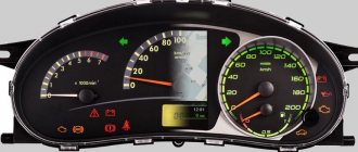
New Priora dashboard
steering column switch with joystick Kalina/Priora/Granta antenna for the Priora instrument panel
You can also buy ready-made kits (device + antenna + switch):
- for Lada Priora - 2170-3801010-55;
- for Lada Kalina 1 - 1118-3801010-55.
old-style Priora dashboard
New-style Priora instrument panel
Replacement of the old instrument panel without CAN with a dashboard with navigation without CAN (2170-3801010-50) is carried out without modifications. We remove the old panel and install a new one in its place, insert the connector with wires, connect the antenna (we fix it on the roof) and, if necessary, change the right steering column switch.
If the old instrument cluster without navigation, but with CAN, and instead of it it is planned to install a new dashboard with navigation with CAN (2170-3801010-60), then you need to rearrange contacts 10-11 to 28-29 (if after connecting it still does not work, change 28 and 29 places).
Pros and cons of CAN bus
Automotive electronics specialists, speaking in favor of using a CAN interface, note the following advantages:
- simple data exchange channel;
- information transfer speed;
- wide compatibility with operating and diagnostic devices;
- a simpler car alarm installation scheme;
- multi-level monitoring and control of interfaces;
- automatic distribution of transmission speed with priority in favor of the main systems and nodes.
But the CAN bus also has functional disadvantages:
- with an increased information load on the channel, the response time increases, which is especially typical for the operation of cars “stuffed” with electronic devices;
- Due to the use of a higher-level protocol, standardization problems occur.
Lada Priora Hatchback Turbo › Logbook › Installing a daytime running lamp controller
Dashboard pinout
Connecting VDO on a Priora car
1 Pink-white To the electric power steering 2 Blue-white To the hazard warning light 3 Gray-blue To the emergency oil pressure sensor 4 Brown-blue To the parking brake switch 5 Yellow-blue To the control unit immobilizer 6 Black To the airbag control unit 7 Yellow To the exterior lighting switch 8 Blue To the right turn signal switch 9 Blue with black To the left turn signal switch 10 White-blue To the ECU 11. To the brake pad wear sensor 12. To the seat belt sensor 13 Black To the traction control control unit 14 Red-blue “RESET” key on the steering column switch 15 Pink-blue To the brake fluid level sensor 16 Black To ABS 17 Green To the headlight high beam switch 18 White To the instrument cluster light control 19 Brown Panel weight 20 White -red Terminal “30” 21 Orange Terminal “15” 22 Yellow-red To fuel consumption sensor 23 Orange-white MK “forward” key 24 White-black MK “back” key 25 Black-white Outside temperature sensor (-) 26 Yellow -green Outside temperature sensor (+) 27 Pink Fuel level sensor 28 Gray Speed sensor 29 Green-white Coolant temperature sensor 30 Brown-red Tachometer (low voltage) 31. Service. Panel diagnostics. 32 Brown-white Terminal “L” of the generator relay regulator
Here we connect: 1) Speed control, connect the white wire to the gray wire (pin 28 of the dashboard connector) 2) Ignition, connect the yellow wire to the orange (21 pin of the dashboard connector) 3) Dimensions connect the blue wire to the yellow (pin 7 of the dashboard connector)
Next we are interested in the mounting block, on the left under the panel, namely K7 - the relay for the high-beam headlights.
A mass is attached above the mounting block with a bolt.
We unscrew the screw from the bottom and take out the mounting block from the panel; we need the relay on the bottom left.
1) Connect the red constant plus wire to the pink wire going to the high beam relay. 2) The green wire in our case to the white-green wire going directly through the fuses to the lamps
What we end up with: 1) When autostarting, the lamps do not light up. 2) The lamps light up smoothly when you start moving. 3) When parked for a long time, the headlights first dim by 50%, then turn off. 4) When the headlights are turned on, the lighting goes into normal mode and the DRL turns off.
The dashboard contains the following parts, without which the car would not function:
- external lighting controller;
- switch for turning and lighting headlights;
- signal regulator;
- instrument cluster;
- wiper regulator.
The device also has an ignition switch consisting of three positions. Secondary components include controls for the heater, alarm and interior cooling.
Circuit breakers
LADA PRIORA 21723
Fuse box of Lada Priora under the hood
F1 (green) 30 Electronic engine management system F2 (blue) 60 power package control unit, engine fan, heated rear window, ignition switch relief relay F3 (blue) 60 cooling fan power supply circuit, horn, alarm, ignition switch, combination devices, interior lighting, brake light, cigarette lighter F4 (blue) 60 Generator Priors F5 (red) 50 Electromechanical power steering F6 (blue) 60 Generator
Fuse box of Lada Priora in the cabin
F1 (blue) 15 Main relay and starter interlock circuit F2 (brown) 7.5 Controller power circuit F3 (blue) 15 Electric fuel pump fuse K1 - Ignition relay K2 - Electric fuel pump relay
Lada Priora fuse box under the instrument panel
F1 25 Electric radiator fan of the cooling system F2 25 Heated rear window Priors F3 10 High beam right F4 10 High beam left F5 10 Sound signal F6 7.5 Low beam (left) F7 7.5 Low beam (right) F8 10 Alarm signal F9 25 Heater Priors F10) 7.5 Interior lighting, instrument cluster, brake light F11 20 Windshield wiper F12 10 Terminal 15 devices F13 15 Cigarette lighter F14 5 Left side light, license plate light, trunk light F15 5 Right side light F16 10 Terminal 15 ABS F17 10 Fog light (PTF) left F18 10 Fog light (PTF) right F19 15 Heated seats F31 or F27 30 Electrical package control unit
When is pinout required (device chips) and how to do it
All car parts fail sooner or later. There are times when they need to not only be repaired, but replaced. The instrument panel may also break, causing it to be removed and a new one installed in its place. This work is easy to do with your own hands if you have at least the slightest knowledge of mechanics. If you are well versed in your Priora (sedan), then you need to perform the pinout in this way:
- First, the dial hands are removed using a regular knife.
- Next, the gasket in the speedometer is scraped out to replace the backlight.
- If there is no need to change the sensors, you can simply remove them and clean them.
Very often, motorists cover the panel with a special LED strip to achieve even lighting.
You can also use CMD diodes, which can be easily fused into glass with a soldering iron. To do this, you need to disassemble the dial and solder diodes directly under the base of the hands. If you understand the purpose of all the contacts, and also know the purpose of a particular connector on the panel, then you can easily do the pinout yourself. The main thing is to carry out everything strictly according to the instructions so that the connection is successful and the panel continues to function efficiently. If you know which is better to install a tidy: with a canbus or a regular one, then it’s better to ask professionals who understand this. If you have no experience in such work, and you do not understand the purpose of certain wires, then the technical service will help you improve the operation of the instrument panel. Of course, you will have to pay for this, but you will not waste your time, and the work will be done efficiently.
Why is a CAN bus still needed, and the principles of its operation?
A modern car has modern on-board electronics with a huge number of control and executive modules, these include all kinds of controllers, sensors, etc..., and for the exchange of information, reliable and fast data transfer was required for communication between devices.
The modern CAN bus provides a duplex system for the simultaneous reception and transmission of digital information, processing it in one unit, where the data transmission speed plays an important role. The implementation of the canbus is a twisted pair cable and has made it possible to significantly reduce the electromagnetic fields that arise during the operation of the generator and other important vehicle systems.
Typically, CAN bus wiring is orange, distinguished from each other by different colored stripes (CAN-Higt is black, and CAN-Low is orange-gray).
With the advent of the CAN bus and the beginning of its use, the circuit of automobile conductors was freed from a certain number of conductors, which provided communication between the control controller between the diagnostic connector, the engine, multimedia (navigation systems on Android OS), the vehicle security system, etc...., using the KWP 2000 protocol.
Vehicle control protocol using the KWP 2000 CAN bus
The data processing speed via the CAN bus can be up to 1 Mbit/s, and the processing speed of information between vital systems in the car, for example, the ABS braking safety system, the engine transmission is 500 kbit/s. In addition to the main systems, the car has an equipment system that includes airbags, multimedia for the car, control units in the car doors, etc.. can be 100 kbit/s.
When exchanging information between any control units and using a transceiver, the signals for receiving and transmitting information are amplified to the required level.
CAN bus topology and waveforms
Each block connected to the CAN bus has a certain input resistance, as a result of which a CAN module load is formed. The load on the central CAN bus depends on the simultaneous connection and use of actuators and electronic control units of the vehicle and various sensors, for example - the resistance of the power unit connected to the CAN bus is on average 68 Ohms, information and command systems “COMFORT equipment” from 2.0 up to 3.5 kOhm. When the entire system is de-energized, the load resistance of the modules operating via the CAN bus is also turned off.
Fragment of a CAN bus with load distribution in the wires: CAN High CAN Low.
System, automotive control units, in addition to various load resistances, also have a data transfer rate, which can lead to an obstacle when processing different types of impulses.
To solve the technical problem of pulses of different characteristics, a gateway converter is used for communication between buses.
The converter is the so-called gateway interface, in a car it is used in the control unit or as a separate unit, etc... The converter interface is used for various input / output of information from the OBD diagnostic connector, via a specific wire connected to the diagnostic connector and connecting the central control unit with the OBD connector via CAN bus.
OBD is a unified diagnostic connector with a lot of conveniences and advantages for scanning a car for errors and diagnostics.
Block diagram of the gateway CAN interface.
As shown in the picture, communication in the car of the CAN bus electronic blocks occurs using different blocks, but doing one thing, the CAN bus power unit, the information command system and the Comfort system, depending on the brand of the car and their composition, the blocks may differ , but the essence of the idea remains unchanged.
Diagnosis of a vehicle for faults is carried out by connecting specialized diagnostic equipment with the necessary software, the so-called CAN bus analyzer, or using an oscilloscope (with a CHN bus analyzer) and a multimeter (digital).