Removing (replacing) the dashboard (“torpedo”)
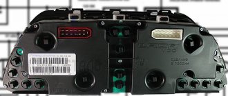
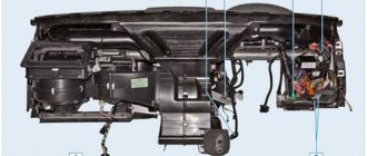
The structure of the instrument panel and its components: 1 — mounting bracket;
2 - amplifier; 3 — dashboard; 4 — glove box body; 5 — lid lock latch; 6 — glove box cover; 7 — lock spring; 8 — lid lock; 9 — shelf; 10 — lid hinge link; 11 — box for small items; 12 — fastening brackets; 13 — radio mounting panel; 14 — instrument panel panel From the instrument panel, disconnect the main cylinder of the headlight hydraulic adjustment (see here) and the instrument lighting switch (see here).
We remove the instrument cluster (see here).
On a car with a carburetor engine, remove the air damper drive (see here)
On a car with an injection engine, disconnect the two connectors of the APS status indicator (see here).
Remove the central panel for attaching the radio (see here).
Using a Phillips screwdriver, unscrew the three self-tapping screws securing the trim of the right windshield pillar... |
|
|
|
|
|
|
|
Remove the instrument panel from the pins by pulling it towards you...
Install the instrument panel in reverse order.
Video
Source
Possible faults
If the instrument panel of the VAZ 21214 has stopped working, this may be caused by various reasons.
What malfunctions are typical for the device:
- Light bulbs don't work. If all the backlight fails at once, most likely the problem lies in poor power supply. If only a few or one lamp does not work, then the indicator should be replaced with a new one.
- The speedometer does not work. An electronic problem can be solved by dismantling the device and looking for a bad contact or a failed board element. The problem of tachometer breakdown is solved in the same way.
- Mechanical damage to the device due to impacts and other impacts on it. If the device stops working because of this, it must be removed and tested to determine the failed element.
- Broken wires, this malfunction can also be attributed to mechanical failures.
- Once connected, the new device may not work due to incorrect connection.
- Oxidation of the contacts on the plugs, which may cause sensors and controllers to not work. The problem is solved by cleaning the contacts.
Removing the instrument panel (combination), replacing the instrument panel illumination lamps and warning lamps
We remove the instrument cluster to replace it, as well as to replace indicator lamps and instrument backlight lamps, the speedometer cable, and to access the instrument panel mounting points.
Note. The instrument panel mounts may vary slightly depending on the year of manufacture and modification of the vehicle.
Using a Phillips screwdriver, unscrew the two self-tapping screws securing the instrument panel panel to the instrument panel itself.
Pull the upper part of the shield towards you, overcoming the resistance of the two latches.
Two latches (latches) are located in the upper corners of the shield.
|
|
Move the instrument cluster away from the panel
and on cars before 2009, we also unscrew the union nut of the flexible shaft (cable) of the speedometer drive.
We disconnect the two wire blocks: the left one is white, the right one is red.
We remove the instrument cluster.
Location of instrument cluster lamps (after 2009): 1 — backlight lamps; 2 control lamps.
Lamps on all modifications of devices are replaced in the same way, only their location differs. (lamps used)
On the removed instrument cluster we replace:
indicator lamp by turning the socket counterclockwise and removing it (the photo shows the battery charge indicator lamp),...
|
We install the lamps and instrument cluster in the reverse order.
Video
Source
Checking the sensors.
In order to check the DC, you need to have a multimeter, then follow a certain procedure:
- Turn off the sensor.
- We connect the red (positive) probe to the DC contact.
- We connect the black (negative) probe to ground.
- We fix a tube of suitable diameter onto the shaft in order to be able to rotate it.
- We switch the multimeter switch to low voltage measurement mode.
- It is necessary to rotate the shaft and observe the readings: as the speed increases, the readings on the multimeter display will increase. If the readings do not change, the sensor is faulty.
Another method does not require removing the sensor. To do this, you need to jack up one wheel so that it is at a distance from the ground and can rotate freely. After this, you need to connect a multimeter to the DC connectors. You need to rotate the wheel and observe the readings of the device. A change in voltage will also indicate performance.
Dashboard Niva 21214
The instrument panel is present in any car. It combines a lot of different devices for monitoring the car. This part of the car is also sometimes called the dashboard. One important rule must be observed on any dashboard: it should not block the driver’s view and must provide full visibility of its instruments. On the VAZ 21214 car, all these rules are followed with precision.
Since this is an off-road vehicle, visibility here should be maximum, and information about the condition of the vehicle should be maximum.
Salon
Everything is as simple as possible here. There is as much comfort as you need to get from point A to point B. No more and no less. Of all the options that make it easier to interact with this car, only power steering is available in this configuration. Fortunately, it is reliable from the famous German company ZF.
Otherwise, there are honest mechanical window regulators, mirror adjustment levers, mechanical rods for moving the heater flaps, and so on. In general, this particular configuration is as mechanical as possible. There are no auxiliary security systems or electronic assistants here. Everything is like in the good old Soviet cars.
And in general, the Niva, despite all the options that have been added to it today, remains a Soviet car.
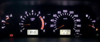
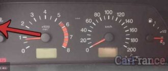
Panel Contents
On the VAZ 21214, on which the injector is installed, there are a lot of different instruments on the panel, among them you can find:
- Speedometer and tachometer (which report the vehicle speed and crankshaft speed).
- Engine temperature indicator.
- Fuel level indicator in the gas tank.
- Turning light indicator.
- There are a lot of indicator lamps that indicate breakdowns: battery charge, parking brake, oil pressure in the engine lubrication system, “check engine” lamp, emergency lamp of the entire brake system.
- Odometer (counts the kilometers that the car has traveled since it left the assembly line).
Shnivy tidy does not work: reasons
Usually this is damage to the module's power circuit, moisture/condensation on the board, or mechanical damage caused by improper repair.
The problem is simple when studied in detail, and can be easily eliminated without the help of specialists.
The shield does not light up
If it just goes out (the backlight has failed), check the corresponding fuse inside the mounting block. Next you need to follow the wires towards the tidy. Here the condition of the contact groups and the presence of oxidation on the terminals are checked. If there are such problems, the problems should be eliminated.
Shnivy's shield is blinking
A typical problem in cars that are driven on rough terrain or broken roads. A symptom of trouble is that the device periodically goes out while driving or blinks quickly.
Check the wiring and connecting terminals for possible damage or loose contacts.
Instrument needles Strings stuck
In such a situation, check the systems.
- Fuse and power circuits of the interior lighting line. The design of the network is such that the power is crossed, which causes problems.
- Mass disappears on the connected elements of the on-board circuits.
Significance of the torpedo
The instrument panel includes all of the above elements and is located in such a way that they are always visible to the driver from any position. Experienced drivers note that it is necessary to carefully monitor the condition of all devices, since the condition of the entire VAZ 21214 car and the injector engine depends on their performance.
Dashboard Niva 21214
For example, the battery charge sensor can notify you in advance of a bad charge, and the car owner will understand that the belt driving the generator has become unusable. When the belt finally comes to an end, it will first begin to whistle bizarrely, and then completely burst.
If this happens on a long journey, the car will be immobilized. Also, the instrument panel has a seemingly simple VAZ 21214 engine temperature sensor, since it is imperative to monitor how the injector heats up. However, it is precisely this that can prevent engine overheating.
Using it, the driver can determine when the temperature began to rise sharply. If this happened while the car was running and driving for a long time, then this may be evidence that the coolant pump drive belt has broken.
By looking at the instrument panel in time, you can prevent sudden overheating of the engine.
Engine
We also recommend that you pay attention to our expert’s article, which discusses the technical characteristics of the Subaru Forester. You can read about the technical characteristics of the Kia Rio in the detailed and interesting material from our expert
You can read about the technical characteristics of the Kia Rio in the detailed and interesting material from our expert.
Additionally, we advise you to study a very interesting and useful article in which our specialist examines the technical characteristics of the Nissan Xtrail.
To transform the VAZ 2123 engine, you will have to delve deeper into the topic of tuning. If you don’t know the basic concepts of the device, it’s better to avoid manual manipulations. Realize that you, as the owner, will have to get into the design of the engine, change specific elements and perform other operations, errors in which can be fatal. So, if you are confident, go for it.
- Install new piston rings and crankshaft. This way you can increase the engine volume by 100 ml. Despite the tiny change at first glance, the technical parameters will actually improve significantly.
- The possibility of chip tuning can be expanded by installing a new control unit.
- Replace the injectors. Prioritize efficiency and quality if you want to achieve fuel consumption that benefits both dynamics and power.
- You can also work on the geometry of the engine. Increasing the diameter of the wells and valves of the inlet and outlet channels will help you in this matter.
- You can replace a traditional catalyst with a flame arrester, which will significantly transform the dynamics of the car and the operation of the exhaust system.
Removing the panel
Sometimes it happens that it is necessary to remove the panel, often when it is necessary to replace some faulty device on the VAZ 21214, for example, a sensor for the condition of the injector. Doing it yourself is not that difficult. First we will have to unscrew and remove all the trim around the panel to get to the mounting bolts. The next step will be to unscrew the screws securing the heater arms. Next, you need to unscrew two nuts under the panel with a wrench; they are located in the steering wheel area. Now unscrew all the bolts around the instrument cluster. Now we simply find all the screws around the perimeter of the panel and forcefully remove it from the studs.
Source
Fuse location
All fusible links used in the electrical circuit of the Niva 2121 car are divided into two groups. They are located in the fuse boxes located under the dashboard to the right of the driver's seat. You can easily find a description of each of these safety devices, as well as their technical characteristics, in your vehicle's owner's manual. If any electrical equipment in your car has failed, first of all you need to check the serviceability of the fuse
To do this, it is very important to follow the following safety rules:
- Before replacing the fuse link, it is necessary to identify and eliminate the cause of its failure;
- In no case should you install fuses that do not meet the requirements of the car manufacturer;
- It is strictly forbidden to close the contacts of the inserts with any metal objects;
- Do not remove fuses from the block using a screwdriver or knife without first turning off the power supply.
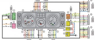
In the figure below you can see a detailed diagram of the location of the fuses of the Niva 2121 car, as well as the connections of all electrical equipment.
How to remove the complete instrument panel (dashboard) Lada Niva Legend
In 2022, Lada 4×4 (now Niva Legend) received interior updates. The SUV has a new instrument panel assembly (dashboard). How to remove it yourself is described in the factory’s technological instructions.
Open the hood and disconnect the earth wire terminal from the battery (spanner 10).
Open glove compartment lid 1, Figure 3-1.
Unscrew screws 3 securing the glove box to instrument panel 2 (Phillips screwdriver).
Figure 3-1 – Fastening the glove box: 1 – glove box; 2 – instrument panel; 3 – glove box fastening screw
Unscrew the screws 2, Figure 3-2, securing the lower right part of the instrument panel 1 (Phillips screwdriver).
Figure 3-2 – Fastening the lower right part of the instrument panel: 1 – instrument panel; 2 – instrument panel fastening screw
Unscrew nuts 1, Figure 3-3, fastening the upper right part of the instrument panel 2 (replaceable head 10, extension, knob)
Figure 3-3 – Fastening the upper right part of the instrument panel: 1 – instrument panel; 2 – instrument panel fastening screw
Remove the central trim (instructions).
Remove the instrument cluster (instructions).
Unscrew screws 1, Figure 3-7, securing the trim of the lower part of the instrument panel (Phillips screwdriver).
Overcoming the resistance of the clamps at the bottom of the cladding, remove the cladding.
Figure 3-7 – Fastening the instrument panel trim: 1 – screw securing the trim; 2 – instrument panel trim
Unscrew screws 4, Figure 3-8, securing the instrument panel (Phillips screwdriver).
Unscrew screw 2 securing lighting control module 1, remove the module by disconnecting the instrument panel wiring harness block from it (a Phillips screwdriver).
Remove handle 3 for controlling the headlight hydraulic adjustment.
Unscrew the nut securing the hydraulic corrector control mechanism to the instrument panel (replaceable head 21, knob).
Figure 3-8 – Fastening the lower left part of the instrument panel: 1 – lighting control module; 2 – screw for fastening the lighting control module; 3 – control handle for headlight hydraulic adjustment; 4 – instrument panel fastening screw
Unscrew nuts 1, Figure 3-9, fastening the upper left part of the instrument panel 2 (replaceable head 10, extension, knob)
Figure 3-9 – Fastening the upper left part of the instrument panel: 1 – instrument panel fastening nut; 2 – instrument panel
Install the instrument panel in the reverse order of removal.
The process of removing the Niva dashboard is also shown in the video:
You will find other reference information on the modification, maintenance and repair of the Lada Niva Legend in this section.
Key words: 4x4 dashboard
Source
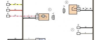
Electrical diagram of VAZ-21214M 2011
ELECTRICAL CONNECTION DIAGRAM FOR FRONT WIRING HARNESS 21214-3724010-44
- 1 – right headlight;
- 2 – starter relay;
- 3 – front harness block to the instrument panel harness block;
- 4 – air temperature sensor;
- 5 – coolant temperature sensor;
- 6 – oil pressure warning lamp sensor;
- 7 – sound signal VAZ-21214;
- 8 – brake fluid level sensor;
- 9 – left headlight;
- 10 – pads for the front harness, sidelight harness and side turn signal
- right;
- 11 – pads for the front windshield wiper motor harness and electric motor;
- 12 – windshield wiper motor;
- 13 – blocks of the front harness and connecting starter wire;
- 14 – starter;
- 15 – rechargeable battery;
- 16 – generator;
- 17 – front harness block and connecting generator wire;
- 18 – right side turn signal;
- 19 – right sidelight;
- 20 – electric motor for washers;
- 21 – pads for the front harness, sidelight harness and side turn signal
- left;
- 22 – left sidelight;
- 23 – left side turn signal.
IGNITION SYSTEM WIRING HARNESS CONNECTION DIAGRAM 21214-3724026-44
- 1 – controller;
- 2 – diagnostic block;
- 3 – mass air flow sensor;
- 4 – coolant temperature sensor;
- 5 – phase sensor;
- 6 – electric fuel pump module;
- 7– block of the instrument panel wiring harness to the block of the rear wiring harness;
- 8 – ignition coils;
- 9 – spark plugs;
- 10 – electronic accelerator pedal;
- 11 – throttle pipe with electric drive;
- 12 – electric fan of the engine cooling system, right;
- 13 – electric fan of the engine cooling system, left;
- 14 – knock sensor;
- 15 – blocks of the wiring harness of the ignition system and the wiring harness of the injectors;
- 16 – VAZ-21214 injectors;
- 17 – solenoid valve for purge of the adsorber;
- 18 – control oxygen sensor;
- 19 – diagnostic oxygen sensor;
- 20 – crankshaft position sensor;
- 21 – APS control unit;
- 22 – APS status indicator;
- 23 – ECM fuse block;
- 24 – fuse for the power supply circuit of the electric fuel pump;
- 25 – electric fuel pump relay;
- 26 – left engine cooling system electric fan relay;
- 27 – relay for the electric fan of the right engine cooling system;
- 28 – ignition relay;
- 29 – ignition system wiring harness block to panel wiring harness block
- devices.
INSTRUMENT PANEL WIRING HARNESS CONNECTION DIAGRAM 21214-3724030-44
- 1 – additional relay;
- 2 – relay-interrupter of direction indicators;
- 3 – windshield wiper relay;
- 4 – ignition switch;
- 5 – alarm switch;
- 6 – rheostat;
- 7 – switch for headlights and direction indicators;
- 8 – windshield wiper and washer switch;
- 9 – main fuse block;
- 10 – additional fuse block;
- 11 – instrument cluster;
- 12 – external lighting switch;
- 13 – rear window wiper switch;
- 14 – rear window heating switch;
- 15 – rear fog light switch;
- 16 – heater motor switch;
- 17 – additional resistor of the heater electric motor;
- 18 – heater electric motor;
- 19 – relay for high beam headlights;
- 20 – low beam headlight relay;
- 21 – rear window heating relay;
- 22 – rear fog light relay;
- 23 – cigarette lighter VAZ-21214;
- 24 – differential engagement sensor;
- 25 – brake signal switch;
- 26 – reverse lamp switch;
- 27 – handbrake warning lamp switch;
- 28 – illuminator;
- 29 – illuminator;
- 30 – instrument panel harness block to the front harness;
- 31 – block of the instrument panel harness to the radio;
- 32 – block of the instrument panel harness to the ignition system harness;
- 33 – instrument panel harness block to the rear harness;
- 34 – indicator lamp for turning on the differential;
- 35 – control lamp for heated rear window;
- 36 – clutch pedal position signal switch;
- 37 – speed sensor.
REAR HARNESS DIAGRAM 21214-3724210-44
- 1 – rear wiring harness block to the instrument panel wiring harness block;
- 2 – rear wiring harness block to the ignition system wiring harness block;
- 3 – switch for the interior lighting in the driver's door pillar;
- 4 – switch for interior lighting in the passenger door pillar;
- 5 – left interior lamp;
- 6 – right interior lamp;
- 7 – electric fuel pump with fuel level indicator sensor;
- 8 – rear window heating element;
- 9 – additional brake signal;
- 10 – right lamp;
- 11 – left lamp VAZ-21214;
- 12 – license plate light;
- 13 – license plate light;
- 14 – electric motor for rear window wiper;
- 15 – rear window washer electric motor.
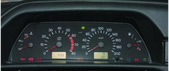
Design Features
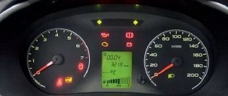
What can the instrument panel tell us? The Chevrolet Niva is designed in such a way that its panel unites all the control devices of the car. It includes:
- speedometer;
- odometer (counter of kilometers traveled);
- tachometer (crankshaft revolution counter);
- coolant and ambient temperature indicators;
- fuel level indicator;
- 12 control (signal) lamps.
Important: the shield has an electronic design and cannot be repaired if it fails! Spare parts in the form of individual panel units are not available for sale. The only exceptions are signal and lighting lamps
In other words, if at least one indicator fails, you will have to buy an assembled panel.
Also interesting: Signs of a faulty crankshaft position sensor
Video “Replacing tidy at home”
The main nuances and features of replacing the control panel on the Niva are shown in the video below (author - Vladimir Kucher).
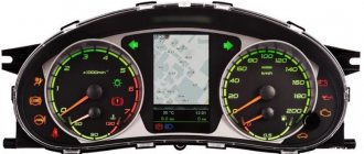
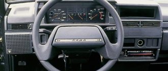
VAZ 2121 or Niva has been produced since 1977. During the entire production period, the body of the SUV changed slightly, and the interior was modified, for example, changes concerned the instrument panel. Let's look at the types of Niva 4x4 dashboards and their descriptions.
The most common instrument combinations (catalog numbers):
- 2121-5325120 - the very first model;
- 21213-3801010 - intermediate model;
- 21150-3801010 - modern model.
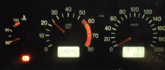
Despite the fact that the instrument panels are different, the indicators showing the status of the vehicle systems remain unchanged and are divided by color:
- Green and blue lamps are informational;
- Yellow lamps are informative (Attention!);
- Red lights are emergency lights, movement is prohibited!