Probably, hardly anyone will argue with the fact that the VAZ “ten” is not the pinnacle of design thought. However, there is nothing surprising here, because this car was designed back in the last century. At the same time, the compensator, and quite a serious one, in this case is the price. In other words, a certain compromise is proposed - the imperfection of the car in exchange for an acceptable cost. Well, the choice is ultimately made by the car owner himself, deciding whether this option is suitable for him.
You can talk about the advantages and disadvantages of this model for quite a long time. However, this is not what we are talking about now. Those who decide that the “ten” is a suitable option in terms of the ratio between price and quality often want to somewhat refine their iron horse during operation, making changes to both the exterior and the interior.
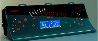
If we talk about tuning the car interior, then one of the main objects of improvement here is the dashboard. Many people simply don’t like the native version, which, frankly, doesn’t look very attractive. Yes, after the “Zhiguli” this is an undoubted step forward, but it’s already the 21st century outside the window, and I want something more beautiful and pleasing to the eye.
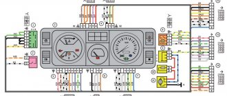
Which wires go where on the VAZ 2110 instrument panel pinout
Let's be honest - the VAZ 2110 does not have the most beautiful “native” instrument panel, neither on the first cars nor on the “improved” ones.
Therefore, many owners of this model are trying to make it more modern and somehow decorate it (with LEDs, beautiful lights, etc.). But, before you decide on some kind of upgrade, it is necessary that you have before your eyes the pinout of the instrument panel for the VAZ 2110, otherwise you can simply get lost in a heap of wires, sensors and buttons. Moreover, it will be useful regardless of whether you completely change the panel, or simply make some additions to the dashboard of your VAZ 2110.
Diagnosis and troubleshooting
If the instrument panel of the VAZ 2110 does not work, then to fix the problems you need to:
- check the lamps and replace faulty elements;
- check the integrity of the wiring using a multimeter or test indicator;
- inspect the condition of the contacts and clean their surface from traces of oxidation;
- check the condition of the fuses;
- test the operation of the devices.
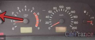
The diagram shows fuses in blue that need to be checked if problems arise with the devices on the VAZ 2110.
Connection knowledge
Before starting dismantling work, you need at least a conventional pinout on paper, otherwise it will be very difficult: you will need to “trace” every wire and every connection that is on the “path” from the devices to the power button.
In fact, the pinout of the VAZ 2110 dashboard is not so difficult to understand, but there are differences between cars produced in different years and at different factories. There is an old model, there is one with a mechanical odometer, and a new (Euro) model, so there are differences in the pinout of the instrument panel, depending on the type to which it belongs.
General diagram of devices
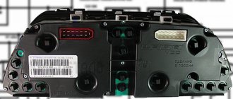
If you look from the back of the instrument panel, here it is in sequence - from top to left to right:
- Fuel level indicator;
- Combination of instrument lighting lamps;
- Right turn control;
- Left turn control;
- Tachometer;
- Next is the block, there are a lot of plugs in it;
- And the top part of the dashboard is completed by an antifreeze temperature indicator.
VAZ 2110 dashboard connection diagram
The lower part of the dashboard (also from left to right and from the back of the dashboard). The following part of the instruments is located here:
- high beam controller (bulb);
- alarm controller;
- brake fluid level control lamp;
- speedometer;
- CHECK ENGINE controller;
- battery charge control;
- parking brake controller;
- oil pressure controller;
- air damper controller in the carburetor;
- outdoor lighting controller.
White block
The connector number, wire color and the unit (assembly) to which it goes are located in the white block as follows:
- The first connector has a black wire. Its purpose is the body (mass);
- In the second - red-brown - this is a low-voltage supply from the electronic control unit - tachometer;
- The third, yellow one is also a tachometer, but this is a high-voltage supply from a coil;
- The fourth, red-blue is Const from the battery + 12V, going through the sixth fuse;
- The fifth, green-white - it is intended to indicate the coolant temperature;
- Sixth, green-yellow – for size fuse F1;
- The seventh connector does not have its own color and goes to the “choke”, the throttle valve;
- Eighth, red and white - CHECK ENGINE light;
- In the ninth and tenth there are 2 orange wires each, leading to 2 power fuses F19+12V;
- In the eleventh there are 2 blue-brown wires leading to the “BK” terminal of the parking brake;
- The twelfth, brown-white is the output “D” of the generator;
- Thirteenth, gray and blue – for the oil pressure sensor.
White block (X1) and Red block (X2) of the VAZ 2110 instrument panel
Red block
The number is the connector according to the account, followed by the color of the wire and an indication of the device to which it goes in the red block of the VAZ 2110:
- Blue and red go to the sensor showing the external temperature;
- Orange - power fuse F19+12V;
- Black, 2 wires – ground, body;
- White - light switch for all devices;
- Blue - right direction indicator;
- Blue and black - left turn signal;
- Blue with pink - TJ level;
- Brown – leading to the trip computer;
- Gray - speed indicator;
- Pink - Fuel gauge (terminal “T”);
- 2 black-green wires - high beam fuse (F3);
- Blue and white - emergency light switch;
- White - leading to the ignition switch (terminal 50).
Why you should know the pinout
But before you start this kind of upgrade, you need to understand which wire leads where. The pinout of the instrument panel of a VAZ-2110 car is a very important point when “tuning”.
Without this, you risk simply getting confused in a fairly large number of wires, buttons and various sensors.
The pinout will be useful in any case - both when making minor improvements and when completely replacing the instrument panel.
The process of installation and dismantling itself is quite labor-intensive, but if you know the correct sequence of actions, then there is nothing particularly difficult about it.
For these works you will need a minimum set of tools - a screwdriver and pliers.
For those who are doing this for the first time, it is best to stock up on self-adhesive pieces of paper, like those on which prices are written in stores, and a pen.
With their help, at the time of disassembly, you will indicate, firstly, the sequence of dismantling the parts, and secondly, which wire is connected where.
At first glance, this may seem time-consuming, but in fact, for beginners, such markings will help them put the panel back together faster.
At the same time, before starting work, it is best to stock up on a pinout diagram - at least conditional.
After all, during the work process you need not to confuse anything and correctly understand each wire and connection during the reassembly process. It is worth noting one very important point.
By and large, understanding the pinout of the panel of the “tenth” family will not be difficult even for a beginner.
But you need to remember that there are certain differences here, depending on the plant where the car was manufactured and the year of its manufacture. For example, the instrument panel may be an old model, with a mechanical odometer. If the odometer is electronic, then this is a newer version. Accordingly, there are certain differences in pinout between these panels.
Which wire goes where?
- fuel level indicator;
- dashboard lighting lamps;
- control of right and left turns (separately);
- tachometer;
- block with many plugs;
- coolant temperature gauge.
As you can see, there is really nothing particularly complicated here. At the bottom of the instrument panel on the back side there are controllers:
- high beam;
- "emergency lights";
- CHECK ENGINE;
- battery charge;
- parking brake;
- oil pressure;
- air damper (for models with a carburetor);
- outdoor lighting work.
Replacing the bushings of the lower arm of a VAZ 2121
In addition, there is also a speedometer and a brake fluid level indicator lamp.
Now let's take a closer look at the pads. There are two of them - white and red. In the first, the connectors and wires look like this (in order):
- Ground wire black.
- Red-brown – low-voltage supply from the ECU to the tachometer.
- Yellow – high-voltage supply to the tachometer from the coil.
- Red-blue - comes from the battery through the 6th fuse Const with a voltage of 12 volts.
- Green-white - leads to the coolant temperature sensor.
- Green-yellow – fuse F1, responsible for the side lights.
- This connector has no color, it goes to the throttle valve.
- Red and white – leading to the CHECK ENGINE indicator light.
- 2 orange wires leading to two F19 + 12 volt power fuses.
- Same as the previous connector.
- 2 blue-brown wires leading to the “VK” terminal of the handbrake.
- The output to terminal D of the generator is a brown-white wire.
- Gray and blue - wire going to the oil pressure sensor.
In the red block, the connector number according to the account, the color of the wires and the devices to which they lead are as follows:
- Red-blue – leads to the external temperature sensor.
- Orange – goes to power fuse F19 + 12 volts.
- 2 black ground wires.
- White – leads to the instrument lighting switch.
- Blue – to the right turn indicator.
- Blue-black - to the left turn indicator.
- Blue-pink - to the brake fluid level sensor.
- Brown – leads to the on-board computer.
- Gray - to the speedometer.
- Pink – to the fuel level indicator.
- 2 green-black wires leading to fuse F3, which is responsible for the high beam.
- Blue-white - to the hazard warning switch.
- The white wire leads to terminal 50 - the ignition switch.
- black;
- red-brown;
- yellow;
- red and white;
- green-white;
- 2 brown wires;
- empty;
- red and white;
- blue;
- orange;
- blue-brown;
- white-brown;
- blue-gray.
As you can see, there are still certain differences, even if they are small. However, these little things are very important.
Therefore, it is best, before starting work, to find out which panel your car has (by year of manufacture and manufacturer), and then find the correct pinout diagram.
However, there is another option - the self-adhesive pieces of paper already mentioned above. When disconnecting the wires, be sure to label them - this will greatly facilitate the assembly process.
Features of connecting BC
In conclusion, I would like to dwell in more detail on such a point as installing an on-board computer. In the typical pinout diagram shown just above, there is only one wire leading to it - brown. But for the correct operation of this device, this alone will not be enough. Therefore, here is a complete pinout diagram for connecting the on-board computer:
- Green wire – comes from the electronic control unit, needed to obtain information about fuel consumption.
- Orange – goes to the ignition switch, to terminal 15.
- White-red - in the same place, only to terminal 30.
- The common ground wire is black.
- Brown – needed to take speed data.
- Red-green - to the positive circuit of the fuel level sensor.
- White - leads to the light control, which is responsible for the lamps that illuminate the instrument panel.
Hello everyone) A new entry is dedicated to the transition from the AutoDevice (AP) panel with one window 2110-3801010-04 to the new VDO Panel 1118-3801010. The devices are completely different, so the modifications affected primarily the pads.
Nuances of work
However, these pinout diagrams for the VAZ 2110 are, so to speak, basic, mostly the same, but there are also differences in color markings (especially by manufacturer). Therefore, you need to either use the instruction manual that came specifically with your car, or, armed with a marker and self-adhesive labels, “write everything out” in detail and not get confused when installing a new instrument panel.
Connecting wires to the VDO panel on a VAZ 2110
Connecting wires to the “Schetmash” panel in Kursk on a VAZ 2110
Connecting wires to the “AP” panel in Vladimir on a VAZ 2110
Connecting wires to the panel from the Kalina car to the VAZ 2110
During subsequent assembly, there will probably be a lot of devices that are not taken into account here, and, taking into account modern realities, many car owners plan to install them on the updated dashboard.
When is pinout required (device chips) and how to do it
All car parts fail sooner or later. There are times when they need to not only be repaired, but replaced. The instrument panel may also break, causing it to be removed and a new one installed in its place. This work is easy to do with your own hands if you have at least the slightest knowledge of mechanics. If you are well versed in your Priora (sedan), then you need to perform the pinout in this way:
- First, the dial hands are removed using a regular knife.
- Next, the gasket in the speedometer is scraped out to replace the backlight.
- If there is no need to change the sensors, you can simply remove them and clean them.
Very often, motorists cover the panel with a special LED strip to achieve even lighting.
You can also use CMD diodes, which can be easily fused into glass with a soldering iron. To do this, you need to disassemble the dial and solder diodes directly under the base of the hands. If you understand the purpose of all the contacts, and also know the purpose of a particular connector on the panel, then you can easily do the pinout yourself. The main thing is to carry out everything strictly according to the instructions so that the connection is successful and the panel continues to function efficiently. If you know which is better to install a tidy: with a canbus or a regular one, then it’s better to ask professionals who understand this. If you have no experience in such work, and you do not understand the purpose of certain wires, then the technical service will help you improve the operation of the instrument panel. Of course, you will have to pay for this, but you will not waste your time, and the work will be done efficiently.
Source
Connecting the trip computer
The mentioned diagram took into account only one, brown wire leading from the red block to the trip computer, but this is clearly not enough. Therefore, let's see how the pinout occurs here.
- The fuel consumption signal from the electronic control unit is indicated by a green wire;
- Orange leads to terminal “15” in the ignition switch;
- Red and white - to terminal “30” in the ignition switch;
- Black, which is common, goes to ground;
- The speed indicator corresponds to brown;
- The positive terminal of the fuel sensor is green and red;
- Responsible for lighting the dashboard white, it leads to the light control.
Make sure that the board is not damaged, on which, in fact, uninterrupted reading of information from your VAZ 2110 depends, and providing it to you through all those sensors and devices that you always see in front of you.
Fuel level indicator
The device indicating the fuel filling level of the tank operates in combination with a control sensor; it is installed in the fuel tank. If the lamp shows a resistance of 284-334 ohms on the board, then the indicator needle will be located near the beginning of the scale.
If the sensor reports a resistance identical to the level of 102-136 ohms, then the needle will move to the middle of the scale. If the sensor value is 8-26 ohms, the needle will move to the very end of the scale. If the resistance and the needle level on the scale do not match, then repair of the machine is inevitable.
VAZ dashboard pinout
When repairing or replacing the dashboard (instrument panel) of VAZ cars with a more convenient and modern version of VDO, made with LEDs, you will need connection diagrams and pinouts of panel connectors. For this purpose, the editors of 2SHEMI.RU have prepared a complete collection of panel contact pinouts for all popular models of this car.
The main symbols that are found on the dashboard of absolutely any car of the VAZ family are: speedometer, fuel gauge, tachometer and sensors to indicate engine temperature.
Power supplies VAZ-2112
Some components are easier to consider by categorizing them into major categories. Let's start researching.
- Battery. The battery is usually a set of 6 modular “cans” equipped with special lead plates and immersed in an acidic environment.
Purpose:
- usually a short-term supply of voltage to various systems even with the engine turned off;
- starting the engine by ensuring the unhindered flow of the required current power to the ignition systems.
- Generator. The device is vital for taking over from the battery after starting the engine. Provides all systems with the necessary power and even recharges the battery while the car is moving. It does the job best when the engine is warm.
- Ignition system. Provides the ability to ignite the fuel mixture in the heart of the car - the engine cylinders. Modern models, including the VAZ-2112, use a system that allows for a non-contact method of igniting fuel, which has replaced the contact method, which is currently outdated both morally and technologically.
Let's pay close attention to the advantages of this modern method in order to fully understand the principle of operation:
- greater strength and retention time of the electric charge;
- glow plugs have a longer service life;
- connections on the contacts remain in working order indefinitely;
- the motor starts quickly and evenly;
- the car has greater starting power and fuel economy;
- The fuel mixture burns more efficiently.
Pinout of the dashboard of VAZ2105, 2106, 2107
Old panel (with oil pressure gauge)
In addition to the presence of an oil pressure indicator, it is worth noting that this instrument panel does not have an air damper indicator lamp (choke), and the emergency oil pressure lamp is located next to the pressure indicator. Because of this, it contains lamps for low brake fluid levels and fog lamps.
White 6-terminal block X1:
- Gasoline level sensor
- Turn signal indicator lamp
- Battery charge sensor (voltmeter -)
- Gasoline level warning lamp
- Overall plus (+)
- Battery charge sensor (voltmeter +)
White 8 terminal block X2:
- Fog lamp warning lamp
- High beam warning lamp
- Dimensions indicator lamp
- Empty
- Battery charge indicator lamp
- Brake fluid level warning lamp
- Empty
- Parking brake warning lamp
Orange 6-terminal block X3:
- General minus (-)
- Tachometer VAZ
- Instrument lighting
- Oil pressure sensor
- Oil pressure warning lamp
- Coolant temperature sensor
New instrument panel (with econometer)
Here, everything is the other way around - there is no oil pressure indicator (instead there is an econometer), instead of a brake fluid level lamp there is a suction lamp (or an engine management system lamp on injectors), and instead of a fog lamp lamp there is an oil pressure lamp.
White 6-terminal block X1:
- Gasoline level sensor
- Turn signal indicator lamp
- Battery charge sensor (voltmeter -)
- Gasoline level warning lamp
- Overall plus (+)
- Battery charge sensor (voltmeter +)
White 8 terminal block X2:
- Dimensions indicator lamp
- High beam warning lamp
- Oil pressure warning lamp
- Empty, but there is a terminal in the wiring that goes to the brake fluid level sensor
- Battery charge indicator lamp
- Indicator lamp for the air damper (choke) or engine control unit for injectors
- Empty
- Parking brake warning lamp (handbrake)
Orange 6-terminal block X3:
- General minus (-)
- Tachometer (if this contact is empty, then the tachometer is on pin #4)
- Instrument lighting
- Empty, and if not empty - to the tachometer
- Empty
- Coolant temperature sensor
Second connection diagram option
Removal and replacement
So, if you are firmly convinced that the Priora instrument panel is faulty, it must be removed for replacement. This operation must be carried out very carefully so as not to damage the trim housing and the wires running under the instrument cluster. First of all, according to the rules, when performing any work on electrical equipment, the battery must be disconnected. In this
In this case, this action also makes sense, since the instrument panel ECU is under constant load to save the parameters. Therefore, you should first disconnect the battery terminal. After this, in the cabin, begin dismantling the device. First, remove the panel under the steering column covering the fuse box. It is held in place by three decorative plastic locks. By turning them half a turn, you can remove it. After this, remove the four screws holding the instrument panel trim panel. Now the combination is completely open.
Now you need to unscrew two more screws holding it and remove the panel. Carefully turn over. Move the connector latch to the side. With this action, it will partially come out of the groove. Now completely disconnect the part and put it aside. If the panel only needs to replace the lamps, then this is quite simple. They come immediately in special plastic nests when sold. On the device they are located in small wells, with the plastic end facing up. Just grab it and turn it a quarter turn counterclockwise. The lamp will immediately fall out. At the end, you need to insert a new one in its place, and turning it clockwise, fix it.
Replacing the panel
Before you put the new panel in place, you should make sure that power is supplied to it correctly. To do this, you will need a test lamp, with the ability to check both the “+” and “-” contacts. You need to know that on the 19th contact of the block there is a common “minus” of the device. Or as they say - “mass”. On pin 20 there is a constant plus from the battery, and on pin 21, a “plus” appears when the ignition is turned on. These connector sockets should definitely be checked before installing a new combination. And after the contacts have been checked, you can connect a new panel to the connector and check it by turning on the ignition. If everything is fine, you can install it in place. Hers or the old one, if it was only necessary to change the light bulbs. You can install the instrument cluster on the “Priors” panel by doing everything in reverse order.
Features of the Gamma instrument panel
The latest models of Priora cars are equipped with a factory navigation system. And in this case, a model called “Gamma” is installed. But do not assume that this is a well-made toy, suitable only for a car with
navigation. No, it installs perfectly on earlier versions of Priora. Since there is practically no need to change anything in the wiring. The only modification: run one wire to the car's diagnostic connector! But this will allow the driver, in addition to the stunning design, to have before his eyes the car’s on-board computer with many functions, including reading error codes from the main Priora ECU. In general, although it is an expensive thing, it is worth the money. In the video, removing the Priora instrument panel:
Pinout of the dashboard VAZ2108, 2109, 21099
Connection diagram of the instrument cluster before 1996.
1 – relay-interrupter for the parking brake warning lamp; 2 – tachometer with voltage stabilizer; 3 – instrument cluster lighting lamp; 4 – temperature indicator; 5 – BSK control unit; 6 – fuel level indicator; 7 – resistor 50 Ohm, 5 W; 8 – control lamp “CHECK ENGINE” for the toxicity reduction system; 9 – control lamp for high beam headlights; 10 – side light indicator lamp; 11 – backup warning lamp; 12 – warning lamp for unfastened seat belts; 13 – control lamp for left direction indicators; 14 – resistor 470 Ohm, 0.25 W; 15 – electronic voltmeter; 16 – control lamp for right direction indicators; 17 – warning lamp for emergency oil pressure; 18 – fuel reserve warning lamp; 19 – control lamp for the carburetor air damper; 20 – indicator lamp “CHECK ENGINE” for the fuel injection system; 21 – parking brake warning lamp.
Instrument cluster wiring diagram after 1996
1 – tachometer; 2 – instrument cluster lighting lamp; 3 – temperature indicator; 4 – BSK control unit; 5 – fuel level indicator; 6 – control lamp “CHECK ENGINE” for the toxicity reduction system; 7 – control lamp for high beam headlights; 8 – side light indicator lamp; 9 – backup warning lamp; 10 – warning lamp for unfastened seat belts; 11 – control lamp for left direction indicators; 12 – battery charge indicator lamp; 13 – control lamp for right direction indicators; 14 – warning lamp for emergency oil pressure; 15 – fuel reserve warning lamp; 16 – control lamp for the carburetor air damper; 17 – indicator lamp “CHECK ENGINE” for the fuel injection system; 18 – parking brake warning lamp; B1 – resistor 91 kOhm; B2 – resistor 50 Ohm, 5 W.
Pinout of the dashboard of VAZ2110, 2111, 2112
- fuel reserve warning lamp;
- dashboard lighting lamps;
- right repeater indicator lamp;
- left repeater indicator lamp;
- VAZ plug block;
- coolant temperature sensor;
- indicator lamp for external lighting;
- carburetor air damper warning lamp;
- oil pressure warning lamp;
- handbrake indicator lamp;
- battery charge indicator lamp;
- VAZ tachometer;
- indicator light “CHECK ENGINE”;
- speedometer dashboard;
- brake fluid level warning lamp;
- hazard warning lamp;
- high beam indicator lamp;
- fuel level indicator.
| White block (X1) | Red block (X2) | ||
| 1 | Housing (weight) | 1 | To terminal “W” of the fuel level indicator sensor |
| 2 | Tachometer (low voltage input from ECU) | 2 | Fuse F19 + 12V power supply |
| 3 | Tachometer (high voltage input from coil) | 3 | Housing (weight) |
| 4 | Const +12V from battery (via 6th fuse) | 4 | Instrument lighting switch |
| 5 | Coolant temperature sensor. | 5 | Turn signal RIGHT |
| 6 | Fuse F1 (side light) | 6 | Turn signal LEFT |
| 7 | Throttle valve (“choke”) | 7 | Brake fluid level |
| 8 | Check Engine Light | 8 | To the trip computer |
| 9 | Fuse F19 + 12V power supply | 9 | Speed sensor |
| 10 | Fuse F19 + 12V power supply | 10 | Terminal “T” fuel gauge |
| 11 | Parking brake, terminal “VK” | 11 | Fuse F3 (high beam) |
| 12 | Generator output “D” | 12 | Hazard switch |
| 13 | Oil pressure sensor | 13 | To terminal “50” of the ignition switch |
Instrument panel electrical diagram Kalina 2
1,2 – blocks of the instrument panel wiring harness to the blocks of the front wiring harness; 3, 4 – blocks of the instrument panel wiring harness to the blocks of the rear wiring harness; 5 – lighting control module; 6 – ignition switch; 7 – on-board computer mode switch; 8 – windshield wiper switch; 9 – instrument cluster; 10 – light signaling switch; 11 – trunk lock drive switch; 12 – diagnostic block; 13 – block of the instrument panel wiring harness to the block of the wiring harness of the air supply box; 14 – rear window heating switch; 15 – alarm switch; 16 – brake signal switch; 17 – multimedia system; 19 – rotating device; 20 – driver airbag module; 21 – sound signal switch; 22 – mounting block: K1 – relay for the electric fan of the engine cooling system; K2 – door lock relay; K3 – additional starter relay; K4 – additional relay; K6 – windshield wiper relay; K7 – headlight high beam relay; K8 – sound signal relay; K9 – relay for low beam headlights; K10 – relay for turning on the heated rear window; K11 – main relay; K12 – fuel pump relay; 23 – electric power steering; 24 – cigarette lighter; 25 – lampshade lighting of the glove box; 26 – glove box lighting switch; 27 – block of the instrument panel wiring harness to the block of the ignition system wiring harness; 28 – engine control system controller; 29 – block of the instrument panel wiring harness to the block of the rear wiring harness 4; 30 – electronic accelerator pedal; 31 – heater motor speed regulator; 32 – heater electric motor; 33 – solar radiation sensor; 34 – ESC switch; 35 – relay (K13) of the electric fan of the engine cooling system 3; 36 – compressor relay (K16); 37 – relay (K14) for heating the windshield; 38 – relay (K15) for heating the windshield 2; 39 – headlight range control regulator; 40 – additional relay; 41 – passenger airbag module; 42 – evaporator temperature sensor; 43 – steering angle sensor; 44 – windshield heating element; 46 – windshield heating switch; 47 – central unit of body electronics; 48 – micromotor reducer of the air flow distributor flap; 49 – gear shift control drive; 50 – controller of the automatic climate control system; 51 – micromotor gearbox for mixing air flows; 52 – micromotor gearbox for recirculation damper drive.
Instrument panels VAZ VDO (LED)
You can install a more beautiful and convenient panel with LED indicators, the so-called VDO panel. Here VDO is the panel manufacturer.
| Connecting VDO on a Kalina car | ||
| 1 | Pink-white | To electric power steering |
| 2 | Blue and white | To the hazard warning indicator |
| 3 | Gray-blue | To emergency oil pressure sensor |
| 4 | Brown blue | To the parking brake switch |
| 5 | Yellow-blue | To the immobilizer control unit |
| 6 | Black | To the airbag control unit |
| 7 | Yellow | To the outside light switch |
| 8 | Blue | To the right turn signal switch |
| 9 | Blue with black | To left turn signal switch |
| 10 | White-blue | TO ECU |
| 11 | . | To brake pad wear sensor |
| 12 | . | To seat belt sensor |
| 13 | Black | To the traction control control unit |
| 14 | Red-blue | “RESET” key on the steering column switch |
| 15 | Pink-blue | To brake fluid level sensor |
| 16 | Black | To ABS |
| 17 | Green | To the high beam switch |
| 18 | White | To the instrument cluster light control |
| 19 | Brown | Panel weight |
| 20 | White-red | Terminal “30” |
| 21 | Orange | Terminal “15” |
| 22 | Yellow-red | To fuel flow sensor |
| 23 | Orange-white | MK key “forward” |
| 24 | White black | MK key “back” |
| 25 | Black and white | Outside temperature sensor (-) |
| 26 | Yellow-green | Outside temperature sensor (+) |
| 27 | Pink | Fuel level sensor |
| 28 | Grey | Speed sensor |
| 29 | Green-white | Coolant temperature sensor |
| 30 | Brown-red | Tachometer (low voltage) |
| 31 | . | Official. Panel diagnostics. |
| 32 | Brown-white | Terminal “L” of the generator relay regulator |
Electrical connection diagrams for the instrument panel of LADA KALINA 11174, 11184, 11194 cars
Electrical connection diagram for the instrument panel of LADA KALINA 11174, 11184, 1119 cars
4
Electrical connection diagram for the instrument panel of LADA KALINA 11174, 11184, 11194 cars.
(click to enlarge).
Dashboard diagram for LADA KALINA 11174, 11184, 11194 cars.
(click to enlarge).
List of elements of the electrical connection diagram of the instrument panel wires of LADA KALINA 11174,11184,11194 cars
1,2,3,4 – blocks of the instrument panel wiring harness to the blocks of the rear wiring harness; 5,6 – blocks of the instrument panel wiring harness to the blocks of the front wiring harness; 7 – block of the instrument panel wiring harness to the block of the wiring harness 8 – block of the instrument panel wiring harness to the block of the front wiring harness; 9 – lighting control module; 10 – ignition switch; 11 – on-board computer mode switch; 12 – windshield wiper switch; 13 – sound signal switch; 14 – light signaling switch; 15 – instrument cluster; 16 – evaporator temperature sensor; 17 – interior air temperature sensor; 18 – air conditioner switch; 19 – controller of the automatic climate control system; 20 – heater damper gearmotor; 21 – rear window heating switch; 22 – alarm switch; 23 – brake signal switch; 24 – cigarette lighter; 25 – electric amplifier control unit; 26,27 – blocks of the instrument panel wiring harness to the radio; 28 – backlight lamp for the heater control panel; 29 – illuminator; 30 – mounting block: 31 – heater electric motor switch; 32 – heater electric motor; 33 – additional resistance of the heater electric motor; 34 – glove box lighting; 35 – glove box lighting switch; 36 – control unit of the APS-6 automobile anti-theft system; 37 – driver airbag module; 38 – passenger airbag module; 39,40 – blocks of the instrument panel wiring harness to the blocks of the ignition system wiring harness.
KZ – additional starter relay; K4 – additional relay; K5 – relay-interrupter for direction indicators and hazard warning lights; K6 – windshield wiper relay; K7 – headlight high beam relay; K8 – sound signal relay; K9 – relay for turning on fog lights; K10 – relay for turning on the heated rear window; K11 – electric seat heating relay; K12 – air conditioner compressor clutch activation relay;
Instrument panel wiring harness – 11186-3724030-20.
added 12/30/10 09:49:55 | viewed 21957 times
VAZ instrument panel indicators - explanation
- coolant temperature gauge.
- tachometer;
- left turn signal indicator lamp;
- right turn signal indicator lamp;
- speedometer;
- fuel level indicator;
- fuel reserve warning lamp;
- side light indicator lamp;
- service brake system warning lamp;
- high beam indicator lamp;
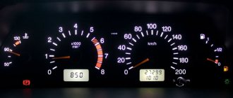
- reset button;
- mileage indicator;
- warning lamp for turning on the hazard warning lights;
- "check engine" warning light;
- time and temperature indicator;
- battery charge indicator lamp or battery lamp;
- parking brake warning lamp;
- oil pressure warning lamp;
- reserve.
VAZ dashboard indicators play an important role in informing the user about malfunctions. They help prevent errors in the system, so it is important to know which indicator means what. How does the panel work? If any problem occurs, the sensor immediately sends information to the panel, and the driver will see an orange signal light up.
The earlier version of the instrument panel had some other symbols, such as emergency oil pressure, handbrake engaged, Chek Engine light, and several others that indicate minor operating errors, but which are no longer used.
Indicators
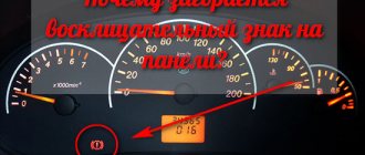
Dashboard
At the moment of ignition, all the lights on the instrument panel light up; after the engine starts, most of the indicators go out. Sometimes, even after starting the engine, one light continues to glow or even blink. This alarms drivers, because it is difficult to say which component in a VAZ 2110 car is malfunctioning; diagnostics are required to determine the breakdown.
We know that the “ten” can be old or new. In both versions, the designations remain identical, the only difference is the location of the light bulbs and their diagram.
At the bottom of the instrument panel there are indicators that indicate a malfunction in the operation of various systems of the VAZ 2110. If they continue to light when the engine is running, it means that repairs will have to be carried out.
We go from left to right:
- The leftmost light, located on the instrument panel, refers to the air damper - the indicator is present in models with a carburetor engine;
- Oil can icon. If the indicator lights up or flashes, it means that the oil compression in the power unit has dropped and the pump is not working properly;
- The letter "P" inside a circle. The dashboard tells you that you forgot to turn off the parking brake;
- A light indicating a faulty battery or generator. Perhaps the alternator belt has broken, there is an open circuit in the circuit, charging is not performed;
- When the “high beam” is working, the headlight icon lights up on the panel;
- On light bulb icon – the indicator shows the lights on;
- "Check Engine" indicator. If it burns, then it is urgent to carry out diagnostics and subsequent repair of the VAZ 2110 engine; serious defects have appeared in the operation of the power plant. The best solution is to stop moving;
- Directly above the faulty engine sign is a warning light.
In addition to these indicators, the front part is equipped with a display showing mileage. Also in this area are the clock and setting keys for it. In the “tens” of the new generation, the screen may be of a narrow format, but the layout remains the same.
Additional panel
New cars have an additional panel with useful indicators. A flashing icon depicting a person with a seatbelt informs you that you should fasten your seat belt - this applies to both the driver and his companions. While driving, the wheel icon may light up; there is a possibility that the pads are worn out and require repair.
- Oil light - lights up when the oil level drops below normal - you should check the level as soon as possible.
- Windshield washer - it tells us that the washer fluid is almost empty.
- The thermometer above the container indicates an increased temperature of the coolant.
- A crossed out arrow icon means the parking or brake lights are not working.
Repair or replacement of the VAZ dashboard
If on a car on the instrument panel none of the indicators installed on it work (speedometer, odometer, tachometer, fuel level and coolant temperature indicators), then the first thing the driver will have to do is check the integrity of fuse F3, which is located in the mounting block . If it has burned out, then before replacing it, you need to find the reason why it burned out, otherwise the newly installed new fuse will have the same fate as the previous one. Most often, fuses burn as a result of a short circuit.
Even if the fuse is intact, then do not be lazy to take it out and check the condition of the contacts. There are cases when the contacts oxidize, and the electrical circuit in this place is interrupted. After making sure that the fuse is intact, the next step is to check the ignition relay, which is located inside the car to the left of the steering column. It is attached to a pin upside down. In the block where this relay is inserted, you can try to short-circuit the power wires using a jumper. If the instrument panel comes to life, the ignition relay will have to be replaced.
If the ignition relay is working properly, there are only two possible reasons for the instrument panel not working: the ignition switch and the mounting block. Before installation on the VAZ-2109 car, the ignition relay and lock contacts often burned out and had to be cleaned by disconnecting the contact group from the lock itself. After changes were made to the principle of supplying voltage to the ignition switch, its contacts began to burn very rarely, but the likelihood of this phenomenon still remained. On the mounting block, in its board, tracks may burn out; in order to see this, the mounting block will have to be removed from the car.
In addition to the reasons listed above, which can lead to failure of the instrument panel, it is also necessary to check the reliability of the fastening of the ground wire. Most common problems:
- burnout of incandescent lamps or failure of the LED group;
- oxidation of connectors;
- electrical wiring fault;
- failure of the fuse box;
- damage to the common contact board;
- no weight on the body (minus) or damage to the dimensions system.
To find a fault, you must use diagnostic equipment, a tester or a voltmeter. If a breakdown is found, you can begin repairs.
Malfunctions and repairs
Instruments or indicators may fail. This could be part of the indicators or even the entire speedometer. VAZ 2110 owners rarely encounter this situation, since the dashboard works properly, especially in domestic cars. Before changing the instrument panel or repairing individual parts, you should make sure that the sensors are working properly - we use the on-board computer.
Inaccurate installation leads to failure of elements. On the instrument panel board, the parts are attached using simple rivets, hence the negative result. The body is constantly subject to vibrations, so the installation simply “falls apart” and breaks appear in the circuit. Repair in this case involves soldering the rivets and thoroughly cleaning the contacts.
- It is necessary to remove the plug; the board does not need to be disconnected from the case.
- The next step is to apply flux to the places on the board with arrows (photo below). Both pads also need to be removed and thoroughly lubricated.
After soldering is completed, the instrument panel can be returned to its place. If you have free time, you can go through the contacts using sandpaper. On older cars they usually oxidize, which can prevent the devices from functioning properly.
You can see how to remove the dashboard in the video below.
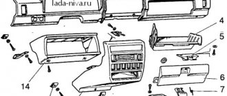
Removing the car dashboard
- Using a Phillips screwdriver, remove the three screws that secure the center console;
- remove the cover, the protrusion located at the bottom, remove the protrusion from the bracket;
- Using a nozzle, unscrew the five screws located in the console on the right and remove the screen;
- Disconnect the terminal with the (-) sign from the battery. If there is a radio receiver, you need to remove it, remove the plug from the shield;
- Disconnect the wires coming from the cigarette lighter, remove the cartridge;
- Using a narrow screwdriver, remove the handle from the levers;
- pull the handle towards the heating and fan switch;
- unscrew the two screws above the panel and the two located under it using a screwdriver;
- unscrew the screw located behind the panel;
- Also unscrew the two self-tapping screws securing the cover;
- disconnect the harness and wire connectors. To avoid confusion when installing the panels, you should mark the order in which they are connected;
- unscrew the fastening bolts;
- unscrew the two self-tapping screws, those that secure the bottom bracket using an 8 key;
- unscrew the self-tapping screw securing the light guide and remove it;
- Also unscrew the screws securing the heating unit;
- remove lamp sockets;
- after removing the external parts, remove the decorative insert;
- unscrew all nuts with a 21 key;
- hydrocorrector, remove its lamp;
- Unscrew the screws that are attached to the cross member on the left.
- Finally, the panel itself is removed. The panel is assembled accordingly in the reverse order.
In general, the repair work is quite doable even with your own hands, but before starting dismantling work, you need at least a pinout mapped on paper, otherwise it will be difficult: you will need to “trace” every wire and every connection that is on the “path” from devices to the power button.
Source
How to remove and disassemble the old-style instrument panel on a VAZ 2110?
To dismantle the instrument panel of a VAZ 2110, high qualifications are not required. Removing and installing another combination does not lead to immobilization of the car and the appearance of errors in the electronic units. The complex itself is equipped with a collapsible body and is divided into several components for repair or tuning.
What tools will you need to remove the panel yourself?
To remove and disassemble the instrument cluster, two screwdrivers are required:
- set of wrenches and sockets;
- short with a cross-shaped sting;
- regular length with a cross-shaped tip.
Preparatory work
Preparation for removing the instrument panel includes:
- turning off the power supply to the on-board network by removing the battery terminal;
- dismantling the steering wheel and column trim;
- glove box removal;
- a number of owners remove the front seats, freeing up additional space for work.
Instructions for removing the instrument panel
Step-by-step disassembly of the VAZ 2110 dashboard:
- Remove the screws securing the shield in the passenger's feet and the shield itself.
- Using a similar scheme, remove the shield from the driver's side.
- Remove the curved plug located under the parking brake lever.
- Remove the four screws securing the center console cover to the brackets. Attachment points are located on the sides, center and trailing edge.
- Disconnect the power window control key pads (if they are installed on the car). Remove the cigarette lighter connector.
- Remove the protective cover of the gear shift lever from the console cover housing. Dismantling is carried out carefully so as not to tear the cover.
- Remove the center console cover from the vehicle.
- Remove the warm air supply ducts to the rear seats.
- Unscrew the nuts securing the lower part.
- Remove the plastic trim on the front roof pillars.
- Remove the radio, heater control unit, clock, on-board display unit.
- Remove the plugs located along the top edge of the panel, in the area of the small non-adjustable deflectors.
- Unscrew the fixing nuts located underneath them.
- Unscrew the screws securing the casing along the lower edge. Two screws are located on the left, the third secures the diagnostic connector. Two more screws are located in the center of the dashboard, at the feet of the driver and passenger. Additionally, there are screws in the fuse box and in the cavity under the glove box.
- Remove the mounting block.
- Carefully remove the plastic casing from the seats. You may need to remove the plastic ties that secure the wiring.