It so happened that in order to install the dashboard from the GAZ 3110 in my beloved VAZ 2105 (with a torpedo and wiring from the 2107), I needed a pinout of the instrument cluster from the VAZ 2107 . To my great surprise and horror, a search in Google and Yandex did not give a single clear result, the information is fragmentary and not always correct, so I decided to put everything together and write a small post-instruction for myself, in case it is useful to someone else
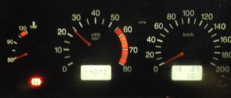
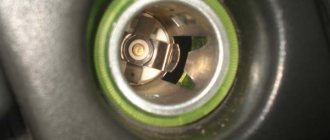
In fact, the confusion arises due to the fact that there are at least 2 most popular types of these devices: the old type with an oil pressure indicator , and the newer one with an econometric indicator. In general, to find out which one you have, look at the upper left device: if an oil can is drawn there, it means you have an older one, and if it says ECON, it means a new one. By the way, in my photo there is a tidy device with an econometer (you can see its piping sticking out on the right).
Pinout of the old instrument cluster (with oil pressure indicator)
In addition to the presence of an oil pressure indicator, it is worth noting that this instrument panel does not have an air damper indicator lamp (choke), and the emergency oil pressure lamp is located next to the pressure indicator. Because of this, it contains lamps for low brake fluid levels and fog lamps.
White 6-terminal block X1:
- Gasoline level sensor
- Turn signal indicator lamp
- Battery charge sensor (voltmeter -)
- Gasoline level warning lamp
- Overall plus (+)
- Battery charge sensor (voltmeter +)
White 8 terminal block X2:
- Fog lamp warning lamp
- High beam warning lamp
- Dimensions indicator lamp
- Empty
- Battery charge indicator lamp
- Brake fluid level warning lamp
- Empty
- Parking brake warning lamp (handbrake)
Orange 6-terminal block X3:
- General minus (-)
- Tachometer
- Instrument lighting
- Oil pressure sensor
- Oil pressure warning lamp
- Coolant temperature sensor
Diagnosis of failure
How to properly check a car's electrical circuit:
- First, diagnose the circuit from the generator to the coil. Make sure that the contacts in this area are not oxidized; there may be breaks. If there is oxidation, then the contacts just need to be cleaned. Bad wires must be replaced.
- Check the functionality of the coil. You need to find out if there is spark. Take out one high-voltage wire and bring it to the metal. When you try to start the engine, a spark should jump between the cable contact and the metal. If it is not there, then it is necessary to more carefully diagnose the main components of the ignition system.
- Also diagnose the performance of the spark plugs and distributor. Sometimes the inability to start the engine is due to the formation of carbon deposits on the spark plugs; if this is the case, then the deposit must be removed. There can be many reasons for the appearance of soot; read more about them, as well as options for getting rid of it, here.
Sorry, there are no surveys available at this time.
Pinout of the new instrument cluster (with econometer)
Here, everything is the other way around - there is no oil pressure indicator (instead there is an econometer), instead of a brake fluid level lamp there is a suction lamp (or an engine management system lamp on injectors), and instead of a fog lamp lamp there is an oil pressure lamp.
White 6-terminal block X1:
- Gasoline level sensor
- Turn signal indicator lamp
- Battery charge sensor (voltmeter -)
- Gasoline level warning lamp
- Overall plus (+)
- Battery charge sensor (voltmeter +)
White 8 terminal block X2:
- Dimensions indicator lamp
- High beam warning lamp
- Oil pressure warning lamp
- My dash is empty, but there is a terminal in the wiring that goes to the brake fluid level sensor
- Battery charge indicator lamp
- Indicator lamp for the air damper (choke) or engine control unit for injectors
- Empty
- Parking brake warning lamp (handbrake)
Signs of trouble
There are several types of condition of the “five” electrical circuit when car owners have to look for a malfunction:
- The car can't move. In principle, there can be many reasons for this. This could be a breakdown of certain components and mechanisms, or problems in the operation of the electrical circuit.
- The car can be driven, but the electrical equipment is not functioning correctly.
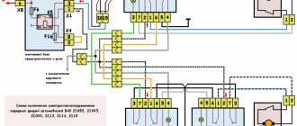
Connection diagram for the instrument panel for the “five”
If you try to start the engine, this does not work, but gasoline flows into the unit without problems, most likely, the problem must be looked for in the circuit:
- As mentioned above, injection versions are more complex in terms of electrical wiring and equipment. As practice shows, in most cases the problem lies precisely in the internal combustion engine control system. For example, if the vehicle system cannot process signals from the regulators and, accordingly, transmit signals to auxiliary mechanisms, most likely the problem is in the circuit.
- If you have a carburetor “five”, then first you need to diagnose the spark plugs, as well as high-voltage circuits. It happens that high-voltage wires become bent or their contacts oxidize, which leads to problems in the operation of the car. In addition, it is advisable to check the functionality of the ignition coil and distributor.
In fact, on any version of the VAZ 2105, be it an injector or a carburetor, one of the main reasons for the incorrect operation of the equipment is contacts. They oxidize or burn, which can result in difficulties in the operation of equipment, in particular, interior lighting or external optics (video author - Max Rublev).
Difficulties in repairing electrical equipment
The biggest problem that can arise during repair work on a VAZ-2105 is a mismatch in the color of the wiring with that indicated in the diagram.
If the car is many years old, then most likely the wiring has been replaced many times. The previous owner of the car was unlikely to be concerned that the wiring colors did not match the colors in the diagram. Most likely, if a car needed urgent repairs, the first wires that came to hand were installed on it. Therefore, a new car owner will have to face difficulties and figure out which wire is connected where. In this case, you can immediately make some adjustments for yourself in the future using felt-tip pens. During repairs, you can paint each wire in the desired color, this can save time for the next inspection or diagnosis. Another difficulty that a car owner may encounter when repairing a VAZ-2105 is partial replacement of the wiring. The previous owner could only replace part of the wires, thereby causing the current owner a lot of trouble. This situation causes even more confusion, and in this case it would make more sense to simply replace all the wiring.
The most common reason for a VAZ-2105 breakdown is damaged wire insulation or lack of contact. In this situation, it is necessary to test all sections of the wiring using a special device. The non-working electrical wiring is replaced with a new one, or part of the non-working wire can be replaced. If the insulation is damaged, then use electrical tape to eliminate this problem.
conclusions
Differences in vehicle modifications often lead to confusion when servicing electrical components. This is why when servicing yourself it is so important to use the original diagram related to a specific car model. This will not only avoid problems, but will also make troubleshooting easier.
Diagram of the carburetor solenoid valve control system
- 1. Carburetor limit switch
- 2. Ignition coil
- 3. Solenoid valve
- 4. Mounting block
- 5. Ignition relay
- 6. Ignition switch
- 7. Wire harness block connected to the electro-pneumatic valve control unit.
- 8. Solenoid valve control unit
A. The order of conditional numbering of plugs in the control unit
Removing the dashboard of a VAZ 2107
“Tidy” VAZ 2107 is a set of indicators and instruments that help the driver monitor the condition of the car, performance of systems and speed. The dashboard also includes the heating and ventilation control panel of the “seven”.
Before removing the dashboard, be sure to disconnect the battery ground terminal.
Further operations are performed in the following sequence:
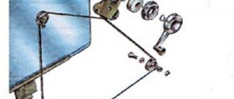
- remove the plastic handles from the heating and ventilation control levers;
- pull out the handle of the daily mileage reset button;
- remove the decorative trim of the self-tapping screw securing the instrument panel;
- Unscrew the fastening screw using a Phillips screwdriver and pull out the panel;
Removing the car dashboard
- using a Phillips screwdriver, remove the self-tapping screws that secure the central one;
- console trim, protrusion located at the bottom, remove the protrusion from the bracket;
- Using a nozzle, unscrew the five screws located in the console on the right, remove the screen;
- Disconnect the terminal with the (-) sign from the battery. If there is a radio receiver, you need to remove it, remove the shield from the plug;
- Disconnect the wires coming from the cigarette lighter and remove the cartridge;
- Using a narrow screwdriver, remove the handle from the levers;
- pull the handle towards the heating and fan switches;
- unscrew the two screws above the panel and the two located under it using a screwdriver;
- Unscrew the self-tapping screw with the panel facing it;
- Also unscrew the two self-tapping screws securing the cover;
- disconnect the harness and wire connectors. When installing the panel there is no confusion, the order of their connection should be marked;
- unscrew the bolts;
- the fastenings are two self-tapping screws, the ones that secure the bottom bracket using a size 8 wrench;
- unscrew the fastening screw of the light guide and remove it;
- Also unscrew the self-tapping screws securing the heating unit;
- remove lamp sockets;
- after removing the external parts, remove the decorative insert;
- unscrew all the hydraulic corrector nuts by 21;
- use a key to remove the lamp;
- unscrew which, the screws are attached to the cross member located on the left.
- At the end the panel itself is removed. The panel assembly is accordingly carried out in the reverse order.
What you will need:
- Leather substitute or leather, a piece of at least 2x2 meters.
- Hot melt adhesive or other suitable adhesive for leatherette and leather, for example, Kleiberit.
- Construction hairdryer.
- Brushes and knife.
Of course, covering a dashboard with genuine leather is very expensive, but it is resistant to mechanical damage and has a more presentable appearance than other materials. But you can also make tuning of the dashboard using artificial coatings. The main thing is to choose the right color and texture so that the car looks stylish and not like a gypsy car. The ideal option would be leatherette. It is easy to work with and has a fairly wide selection of colors.
LED lighting for VAZ-2105 devices
So we buy these BLUE LEDs (you can either white or green, to your taste)
Pay attention to the LED lens made in the form of a funnel; such a lens scatters the light of the LED and it is advisable to use just such diodes. Why blue? With blue LEDs there is a very interesting effect - it seems as if the needle and instrument scales are glowing - like in foreign cars. There is no such effect with white diodes. I don’t know about the other colors. How many diodes will be required? I have a modified instrument cluster (it costs a tachometer and oil, gasoline, temperature from a VAZ 2106, you can read about it HERE) for small instruments I used one diode each, and for large ones (speedometer and tachometer) 4 diodes and one diode lamp. A diode lamp looks like this
they are inserted instead of standard light bulbs. But it makes no sense to insert them into devices instead of ordinary lamps (they will not shine normally). So, we take out the devices and disassemble them. To do this, use a screwdriver to bend the chrome ring around the perimeter. So that it can be removed from the device. The ring will of course be damaged, but it won’t be visible from behind. We remove the ring. And remove the glass from the device. There are two nuts or screws on the back of the device; unscrew them and remove the device from the housing. Next, we study small instruments (in the case of a five-piece torpedo, this is a voltmeter), the visible part of the scale, or rather the scale and the black pad above it. There is a distance between them into which we will push the diode. We take a drill with a drill bit of 7 and make a hole like this from the very bottom of the scale.
And we glue the LED onto the second black cover with sealant. Like this
Historical reference
The VAZ 2101 platform was taken as the basis for production. At its core, it was the same rear-wheel drive five-seater sedan car. The VAZ 2105, with its design, practically copied the models of cars produced in Europe in the early 80s, and cost an order of magnitude lower, which predetermined its popularity in Western countries.
Abroad, the car was named Lada Riva and Lada Nova (depending on the country of sale). Under these names he was shown in video advertisements.
The car plant produced several modifications of the VAZ 2105:
- With the VAZ-2105 index, the car was equipped with a 4-speed gearbox. gearbox and 1290 cc carburetor engine. cm (63 hp);
- The VAZ-21050 was equipped with a 5-speed checkpoint;
- The VAZ-21051 was equipped with an engine from the VAZ 2101 (volume 1200 cc, power 58 hp) with a 4-speed. checkpoint;
- The VAZ-21053 was equipped with a VAZ-2103 carburetor engine (volume 1450 cc, power 71 hp);
- The VAZ-21053-20 was equipped with an injection engine from the VAZ-2104 (volume 1450 cc, power 71 hp), which met Euro-2 requirements. It also came with 5 tbsp. Transmission.
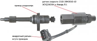
For reference: the electrical wiring of the VAZ 21053 was distinguished by a different form of terminals in the engine compartment. This was caused by the installation of an ECM - an electronic engine management system and additional sensors.