Connecting a towbar (truck trailer) is a simple procedure. Connecting a trailer to a car is really easy, but connecting the electrical to the trailer can already be a bit of a hassle. In such cases, you will need a wiring diagram for the towbar socket. And there are several types of connectors:
- seven-pin (7 pin) European-type connectors;
- American-type seven-pin (7 pin) connectors;
- thirteen-pin connectors (13 pin);
- special connectors.
The most common types of sockets have 7 and 13 contacts. In Russia, 7-pin devices are usually used, and 13-pin sockets can be seen on many cars from Europe and the USA. The difference lies in the use of additional contacts necessary to activate fog lights and other electrical components of caravans that are popular abroad.
Rules accepted throughout the world provide for the installation of left/right turn signals and stop signals on trailers for passenger cars. The connection diagram for a passenger car trailer socket depends not only on the number of contacts, but also on the standard of the country, so a trailer with European wiring cannot be connected to a socket with Russian wiring without modification. If you install it without modification, then the right dimensions of the BTS will not light up.
About connection methods and types of trailer connectors
To transport cargo trailers, a special traction coupling device is used, made of a powerful power steel structure, which is attached to the rear of the steel platform by an automobile mechanism.
A towbar connection diagram is required, which will ensure safety and compliance with road accident regulations. Many cars provide additional options for the car with a detachable unit: a tow bar socket and electrical wires connecting the power supply and control of the car with an additional traction device.
Basically, motor transport mechanisms are equipped with these devices as an additional service when purchasing a car. The towbar socket can be connected to the car yourself; pinout of the towbar socket and installation of electrical wiring is not difficult to do yourself. Let's look at the trailer connection diagrams and the pinout of the towbar socket.
There are the following connection diagrams for the towbar socket:
- Regular Russian standard with a socket for seven groups of connecting contacts;
- European and American standard for thirteen detachable connections;
- Special connector.
By the way, in Russia and America they also use a method for connecting a towbar with seven and thirteen connectors. Thirteen connections are used in the main connection of electrical wiring in transportable caravans.
When installing and connecting the control circuit for the rear parking devices of a vehicle, you must follow the rules for connecting the socket for a passenger car trailer, the correctness and sequence of operations when turning it on.
You should not perform such operations by poking at the contacts of light devices; a short circuit may occur or the automatic protection of the vehicle control unit may be triggered. And you cannot connect conductors using the twisting method; a poor-quality connection can create an incorrect command, and the devices will be blocked from turning on.
Modern car circuits are equipped with various electronic devices that use electronics, modules, and matching units. Therefore, an additional special connector is included in the complete set of devices.
In the pinout of a truck trailer socket, conductors are used from conductors with a cross-section of 1.5 or 2 mm, more precisely, 1.5 mm will have a total of 6 conductors, 2 mm will have one wire.
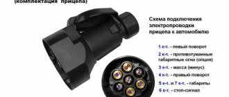
The towbar socket with seven connectors has the following pinout structure:
- left turn signal;
- reverse;
- mass 12V;
- right turn signal;
- right side signal;
- Stop signal;
- left side signal.
The thirteen-pin detachable towbar socket consists of the following equipment:
- left turn indicator;
- rear fog lights;
- weight in the chain 1,2,4-8;
- right turn indicator;
- right side signal;
- Stop signal;
- left side signal;
- reverse signal;
- +12 V constant;
- +12V when the ignition is turned on;
- weight in chain 10;
- Reserve pin;
- weight in chain 9.
Connectors with 13 contacts are characterized by the presence of additional contacts with negative and positive polarity, allowing you to connect additional devices such as cameras, lighting devices, etc.
The detachable connection of the towbar electrical wires with seven and thirteen detachable connections consists of two connecting units: a female socket and a male plug. The towbar socket is mounted on the vehicle next to the towbar mounting point.
The trailer fork is installed with an extended harness of connecting conductors on the trailer in order to create a free docking of the trailer and free installation of electrical wiring.
In cases where a special connector is used in cars with an on-board computer and other electronic devices, it is better to use an electronic coordination unit in the installation of the electrical part of the signal control of the trailer mechanism; in other cases, it is possible to install a manual electrical network for the trailer.
How to connect the socket to the tow bar yourself
A towbar socket is a device necessary for connecting various signals and ensuring the functionality of the electrics on the trailer: brakes, turn signals, side lights, license plate lights, etc. Below we will look at the main types of sockets, talk about connection diagrams and pinout features. We will pay special attention to the purpose of the electronic matching unit and the nuances of connection
- Types of trailer sockets
- Types of connectors
- What is pinout: definition of the term
- What is a towbar socket
- 2 Schemes
- Connection diagrams (pinout)
- What GOST 9200-76 says
- Pinout
- 7 PIN
- 13 PIN
- 5 PIN (ISO 1724)
- Additional connectors
- Why do you need an electronic matching unit?
- What is needed to connect
- Features of connecting trailers Skif-M1, Skif-M2, MZSA and others
- Step-by-step connection of the towbar socket to the car
- Niva Chevrolet
- Best driving instructors:
Types of trailer sockets
When choosing a socket for a passenger car, pay attention to the types of products.
There are two types on sale (according to the number of cores):
Seven-core (7 PIN). Designed to output external lighting sources and is used for standard cargo trailers. Such a socket, in turn, can be European or American (they differ in connectors). The peculiarity of the European circuit is that all seven wires are involved in it.
13-wire (13 PIN). Unlike the previous type, additional connectors are used here to allow you to connect a caravan trailer and ensure the functionality of all lighting and additional equipment (refrigerator, battery charger, etc.). So, to charge the battery, there is a separate conductor, which goes from the machine’s power source to the towbar socket and is protected by an individual fuse insert.
The 13-wire socket has more functionality and is suitable for many cars from the United States or the EU. But purchasing it will cost a lot, and connecting it will require a higher level of skill.
Sometimes situations occur when the car has a 7-pin socket and the trailer has a 13-pin socket (or vice versa). This is not a problem, thanks to the availability of adapters from 13 to 7 or from 7 to 13.
Types of connectors
GOST 9200-76 was the main standard in the USSR, which established uniform standards for the electrical connection of trailed equipment to cars and tractors of that time for all industries. It stipulates that all vehicles produced by Soviet industry are equipped with the same seven-pin connectors.
After the appearance on the domestic market of a large number of foreign-made cars and trailers, the complete interchangeability of car sockets was lost. Foreign cars are equipped with trailer hitches (towbars, or towbars) with electrical connections that are often of different types.
Today in operation you can find the following types of compounds:
- seven-pin connector of the “Soviet” type (according to GOST 9200-76);
- 7-pin Euro connector (has a difference in the wiring cross-section and wiring of the 5th and 7th pins);
- seven-pin (7-pin) American type - with flat pins;
- 13-pin with separation of positive and negative buses;
- 15-pin for heavy cargo trailers (has lines for connecting the return indication from the trailer to the driver of the tractor).
Non-standard types of connectors are used in addition to the basic one for connecting other electrical circuits (rear view cameras, on-board circuits of a caravan trailer and the like).
What is pinout: definition of the term
Before you try to connect the terminals of the trailer to the car, you should know what the pinout of the trailer socket is. In simple terms, this is a diagram of electrical connectors. It allows you to correctly connect the trailer socket to the electrical socket on the car.
Not all drivers are aware that the pinout of the socket may vary for each make and model of car. In addition, some car enthusiasts change trailer lights, therefore, the pinout of the new socket in this case may also become different.
Most trailers for passenger cars are attached to the vehicle using a towbar. This is a special device that not only allows you to securely fasten the trailer to the body of the car, but also allows you to evenly distribute the load on the rear of the car. To correctly connect the trailer and the vehicle, you need to pay attention to the pinout of the trailer socket.
If the components are not connected correctly, the brake lights, left/right indicators, or other LED commands at the rear of the trailer will not work. This is fraught with possible accidents and problems for the trailer owner who was unable to connect the parts correctly.
What is a towbar socket
The towbar socket is a connector with electrical contacts that is used to connect the trailer to the vehicle. It is located near the towbar, and the corresponding plug is connected to it. Using a socket, you can safely and correctly connect the electrical circuits of your car and trailer.
Towbar socket
When connecting an outlet, the term “pinout” is used (from the English pin - leg, output). This is the pin layout for proper connection.
2 Schemes
Schematic electrical diagrams, connecting devices and pinouts of connectors
Connection diagrams (pinout)
When studying the connection diagram for a trailer socket and a car's towbar, it is important to focus on the current GOSTs and rules. They indicate the requirements of government agencies to avoid errors when connecting and operating devices, as well as when checking the electrical connection diagram.
What GOST 9200-76 says
One of the main documents positioning the connection of 7-pin connectors for cars and trucks, as well as tractors, is GOST 9200-76. It was approved and put into operation on January 19, 1976 and is still in effect.
The standard complies with the following ISOs:
- 1185-75.
- 3731-80.
- 1724-80.
- 3732-82.
- 4091-78.
Before the advent of GOST 9200-76, the document GOST 9200-59 was in force, but with the advent of new rules it became invalid.
The following types of sizes are considered here:
- 24 N and 24 S for 24 V voltage;
- 12 N and 12 S for 12 V voltage.
At the request of the consumer, the use of 12N is allowed on car tractors, as well as trailers and semi-trailers with a voltage of 24 V.
- 24 N is equipped with a large socket for 1 contact and 6 small pins. The inner diameter of the 1st contact must be such as to provide the required disconnection force.
- 24 S also comes with one large 1st contact and 6 smaller ones.
- The 12 N has four sockets (pins one, three, four, and six), as well as three spring-loaded pins—pins two, five, and seven. The diameters of the pins must be such that they fit into the plug sockets and provide the necessary force.
- 12 S provides a special design. This socket is equipped with four sockets (one, three, four and six), one recessed 7th socket (3 mm deeper), as well as a pair of spring pins (second and fifth contacts).
What is needed to connect
Before connecting the trailer socket, you need to prepare and buy the necessary material in advance.
The package includes the following equipment:
- Socket cover for tow bar. Please note that there is a cover equipped with a rubber seal. When purchasing, inspect the product for the fit of all casing elements and for the absence of loose housing or contact connections. Pay special attention to the condition of the threaded connection and the fastening of screws to the terminals.
- Wire (one core) with a cross-section of 1.5 sq. mm or more. When purchasing, check the possibility of using it in the electrical wiring of a vehicle.
- Corrugation made of metal or polypropylene. Used to insulate wire harnesses and protect against mechanical damage. The average length is up to 2.5-3.0 meters. Immediately take 20-30 plastic clamps to secure the harnesses.
- Connecting blocks. When choosing, give preference to a model with sockets in which fuses can be installed.
- Tools: set of wrenches, drills and bits, screwdrivers, soldering iron, electrical tape.
The specified equipment is usually sufficient for installation work. If something is missing, the scarce elements can be purchased separately.
Standard car trailer socket diagram - first option
Connecting the towbar wires according to the standard scheme is carried out on vehicles not equipped with an electronic control circuit. To perform the work, a seven-pin trailer socket is used, each of the contacts of which is directly connected to the corresponding electrical power circuit for the rear lighting equipment.
Before starting electrical installation work, the pinout of the 7-pin towbar socket must be carefully studied. Only then is the trailer socket connected. During installation operations, you should use crimp clips that ensure good contact between the conductors. It is possible to remove the protective insulation of the wires and fix them by soldering.
Pinout of 7 pin socket
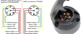
Below is a drawing showing the wiring of a 7-pin connector (socket and plug). The typical colors of wires for Russian-assembled cars are indicated (color deviations are possible). In European machines, not all contacts on the connector may be used.
Pinout of the 7-pin towbar socket (A) and the corresponding trailer plug (B)
Explanation of the picture:
- Left side turn signal control signal.
- PTF connection (in foreign cars the contact may not be used).
- Weight.
- Starboard turn signal control signal.
- Side lights on the left side.
- Brake light control.
- Side lights on the starboard side
Currently, the 7-pin connector is practically not used in modern foreign cars; 13-pin sockets are installed there. If the trailer has an old type plug, you can connect it to the new Euro connector using a special adapter, which is much easier than changing the connector.
Adapter from 7 to 13 pins
LAV boat trailer pinout
Of particular interest is the pinout of contacts in LAV trailers. Let us highlight the contact characteristics:
- Left Turn Signal.
- Rear PTFs.
- Weight.
- Right Turn Signal.
- Reversing light.
- STOP signal.
- Dimensional and contour lamps, room lighting.
Knowing the characteristics of the contact group will help you accurately connect the trailer socket and towbar.
Pinout of 13 pin socket
The advantage is reinforced wiring and the number of connectors:
- 1 – yellow – left direction indicator signal;
- 2 – blue – signal from rear fog lights;
- 3 – white – negative signal for contacts 1 to 8;
- 4 – green – right direction indicator signal;
- 5 – brown – size signal on the right side;
- 6 – red – stop light;
- 7 – black – size signal on the left side;
- 8 – pink – reverse lights signal;
- 9 – orange – permanent positive contact;
- 10 – gray – positive contact during ignition;
- 11 – black and white – negative signal for pin 10;
- 12 – white-blue – reserve contact;
- 13 – white-orange – negative signal for pin 9.
Source: 2shemi.ru
American connecting chips
Many American standards differ from European ones, and trailer hitch socket pinouts are no exception. Here are two types for your reference: 7 and 4 pin connectors.
The 7-pin socket, used in the HOPKINS model range, as well as in other cars (Fig. 8), differs from the European standard practically only in design, which allows, if necessary, replacement with a European analogue.
American 7-pin towbar socket
Designations:
- Connecting side lights.
- +12 V.
- Starboard turning lights.
- Brake light control.
- Weight.
- Turning lights on the left side.
- Reverse signal.
Now let's consider a more complex option - a 4-pin connector (see Fig. 9). If you try to replace it with a European 7-pin socket, problems will arise.
4 pin connector
Designations:
- Weight.
- Control of side lights.
- Left side turn signal and brake light control.
- Starboard turn signal and brake light control.
As you can see, the difficulty is due to the fact that the turn signals and brake lights are controlled along the same line. There are two ways to solve the problem:
- Not entirely correct, but the easiest way: connect directly to the stops and turn signals. Note that in some cars the wiring may not withstand the additional load, so it is better to solve the problem in another way.
- This option is somewhat more complicated, but more correct: you need to completely extend the wiring under the European connector. For example, in a Chevrolet Tahoe, to do this you need to remove the instrument panel, find wires with separate signals for the turn signals and brake lights, connect to them by stretching the electrical wires from the towbar socket through the entire interior of the car. You can make the task a little easier if you take the signal for the brake lights from the rear fender; it is displayed there on almost all cars. In this case, you only need to pull two wires.
Good day to all! Next up is connecting the trailer. This is quite a relevant topic, which is closely related to the correct and safe operation of a towed vehicle.
Everyone knows that there is a socket on the towbar, and there are plugs on trailers. Here is what many people think is a simple electrical circuit. But in fact, when connecting a trailer to a passenger car, you need to take into account a number of nuances. And it doesn’t matter whether you connect to an American car, a Euro car or a domestic product.
Each connector and plug has its own function. When connecting the towbar, trailer and car, you need to be extremely careful. There is a standard and non-standard pinout for Russia. Various features and tangles of wires often frighten those who decide to connect a car and a towed vehicle with their own hands.
But don't be alarmed. Everything has its own solution. If you decide to tackle the electrical wiring issue yourself, I will try to give you some practical advice and recommendations.
Pinout of 15 pin connector
This type of connector for connecting trailers and semitrailers is an accepted standard for tractors from almost all manufacturers, including American ones. Considering the requirements for trailers of this class, a standard 13-pin connector is not suitable for powering and controlling their electrical equipment.
Appearance of a 15 pin socket
Matching table for 15-pin connector.
| Pin number | Coloring | Function |
| 1 | Yellow | Left side turn signal |
| 2 | Green | Starboard turn signal |
| 3 | Blue | PTF |
| 4 | White | Earth |
| 5 | Black | Parking lights on the left side |
| 6 | Brown | Side lights on the right side |
| 7 | Red | Brake light control |
| 8 | Pink | Reverse signal |
| 9 | Orange | +24 V |
| 10 | Gray | Transmission of an alarm signal from sensors installed on the brake pads |
| 11 | White-black | Signal from spring brake pressure sensors |
| 12 | White-blue | Bridge lift control |
| 13 | White-red | exchange of information signals |
| 14 | White-green | CAN-H |
| 15 | White-brown | CAN-L |
Rear view camera pinout
A rear view camera is an excellent device for monitoring the space behind the car when reversing and parking.
Most modern cars have parking sensors. But they have disadvantages - they cannot always detect a long thin object - fittings, for example. It happens that their sensors simply fail - either mechanical damage, or a wire break. The result is known - editing or replacing the bumper. This will not happen with a camera, and the visual picture gives much more than signals from the parking sensors.
The choice is now extensive, for every taste. And you can easily find a suitable option in our catalog: https://electro-kot.ru/elektronika-dlya-avto/kamery-zadnego-vida/
When choosing, be guided by the principle of necessary sufficiency - there is absolutely no point in overpaying for useless surpluses. This concerns the quality of the picture, the number of frames per minute, viewing angle, etc. You need to choose the average one in terms of characteristics, preferably with installation in the license plate - it has the best view of the space from below, convenient mounting, the hole for the cables is covered by the license plate, and necessarily with infrared illumination. Daylight hours in Russia are short, and the light from reversing lights at night may not be enough. On some cars, the tail lights (or even just one light at all) have only a warning function, and not a lighting function.
The pinout of wires can be from 3 to 6. In this article we will not dwell on various types of devices; we will only consider connecting devices with a pinout of 4 and 5 wires, that is, 5 pins and 4 pins.
Rear view camera pinout: 5 wires
If the device you have chosen has 5 output wires, then see diagrams 1 and 2 for possible options. The only difference is the presence or absence of connectors at the camera output.
| Scheme 1 |
Let's consider how and where to connect them.
This device has 3 wires, like a regular one - two wires for powering the camera, one is a video output wire with a tulip connector for connecting the camera monitor. Two more wires were added to power the camera backlight at night. In addition, in such a circuit a control wire can also be added to use additional capabilities (usually to turn on the monitor, if necessary). Comes in one cable with video output. According to the electrical diagram, the power wires should definitely be connected to the reversing lights, the video output to the monitor, but the backlight wires - turning on the infrared LEDs - is at your discretion.
The fact is that when the infrared illumination works, the image becomes black and white. Logically, it should be connected together with the camera - saving the resource of LEDs, but then you will never have a color picture. Another way is to connect the backlight to the side lights - during the day the picture will be in color, at dusk - black and white. But then the backlight will always be on at night, and the resource of the LEDs will be wasted. And in cars that do not have running lights, you always have to turn on the low beam (and therefore the side lights) and there is no point in connecting the backlight to the side lights at all - only to the reversing lamp.
| Scheme 3 |
Camera pinout option with switch 2, which can change the specularity and turn the marking on and off.
| Scheme 4 |
With this device, power is supplied when the ignition is turned on, and activation occurs from the reversing lights.
Step-by-step connection instructions
It is recommended to connect the towbar socket to the car with your own hands without cutting the standard wires, but using intermediate connecting blocks, as when installing factory adapters.
You need to purchase the necessary materials:
- the connector itself with a protective cover;
- electrical blocks of suitable design;
- cable with colored conductors with a cross-section of at least 1.5 mm2;
- clamps;
- protective corrugation.
Scheme of work:
- Cut a piece of cable to the required length with plenty of room for processing the ends.
- Remove insulation and tin the wire tails.
- Pass the cable inside the corrugated sleeve.
- Solder the contacts in the socket body, referring to the socket diagram of the car's tow bar.
- Secure the wires in the connecting blocks for the rear lights, also checking their order.
- Insulate all connection points and connect the pads to the car's lighting connectors.
- Lay the harness to the installation location on the tow bar, secure it and close the holes in the body with plugs.
It is better to use silicone sealant to insulate cable entries into sockets and connectors.
Results
Connecting the hitch and the trailer socket of a car or truck does not cause any difficulties. To do this, you need to immediately understand the pinout and follow the connection rules.
If for some reason the pins do not fit together due to different numbers/types of connectors, adapters can be used. At the same time, always check that the lighting equipment works correctly in all modes and that the computer does not display errors on the dashboard.
Why do you need an electronic matching unit?
Not in all cases it is possible to simply connect the sockets of the towbar and trailer. If the machine has complex electronics, a matching unit will be required.
Its use allows you to avoid errors when testing the operation of lighting equipment and vehicle electrical systems.
In addition, the matching unit is an invariable thing when it is necessary to transmit a signal using a multiplex bus.
The connection diagram is as follows:
- Signals from the car are sent to the matching unit.
- The latter processes the information.
- If there are no conflicts, the signal is transmitted to the trailer of the car or truck.
For correct operation, the unit must be connected to the battery and the wires must be connected correctly (taking into account the pinout).
The connection diagram is shown below.
Prices for towbars for VAZ 2112 1999-2008.
| Manufacturer/country (for body type) | vendor code | max horizontal load (kg.) | max vertical load (kg) | Do you need to remove the bumper? | Need to cut the bumper? | Electrics | Matching block | Price |
| Bosal-Autoflex/Russia (sedan, station wagon, hatchback) | 1209-N | 900 | 75 | No | No | Wires and socket included | not needed | 2,850 rubles |
| Leader-Plus/Russia (hatchback) | VAZ 05-N | 900 | 75 | Yes | No | Wires and socket included | not needed | 1,720 rubles |
Direct connection diagrams
They go where the brake lights are. When removing reflective covers, take into account the minimum pressing of the cushioning foam, which serves to prevent dust from being sucked into the interior. Although there are connection diagrams on the Internet, performing this procedure yourself is not so easy. Before connecting, it would be good to study the approaches to the wires. A nuance: on the one hand, cutting the wiring is too lazy, on the other, it’s a pity. Therefore, for the lazy method, connectors with three ends are provided: two with plugs that connect standard devices, and one end with bare wires to the towbar socket.
In addition, you will need additional materials:
- Socket with cover.
- Switching blocks. They come with fuse sockets.
- Wire with a cross section of 1.5-2 mm square. Insulated stranded or single-core wires are used.
- Silicone automotive sealant.
- Tourniquet. It is a 3-meter corrugated pipe made of plastic or metal.
- Clamps for fixing the harness.
It is not difficult to purchase one set. The factory version requires complex switching for the following reasons:
- Using a smaller load eliminates melting and short circuits;
- Guaranteed proper operation of lighting fixtures.
In theory, 11 wires are placed in a bundle. Since the right and left sides are synchronous, the switching theoretically fits into the usual 7 wires. But in this situation, there are three lamps per core, and this increases the load. There is another way to divide the current into right and left sides. The number of wires, mounting sleeves, and fuses increases. This circuit complies with safety standards.
Features of the circuit connection of the towbar connector in modern cars
p, blockquote 29,0,0,0,0 –>
Cars produced before 2000 used analog circuits for controlling rear light devices. The greatest difficulty during connection is the correct determination of the location where the corresponding conductor is connected.
p, blockquote 30,0,0,0,0 –>
Many car enthusiasts carried out this work using the “poke” method, sequentially connecting the contacts of the trailer connector to the indicator lamp. With the advent of digital control circuits for lighting devices and other electrical equipment of the car, this method has become dangerous.
p, blockquote 31,0,0,0,0 –>
Video - connecting the towbar wiring on a Nissan Note:
p, blockquote 32,0,0,0,0 –>
”
p, blockquote 33,0,0,0,0 –>
Digital control of electrical equipment assumes that thick conductors do not go directly to the light devices from the steering “dragonfly”, “frog”, relays and other switches to the tail lights, stops and other light devices. The supply voltage and digital control signals are received there.
p, blockquote 34,0,0,0,0 –>
A simple twist-type connection to the tail light conductors is inappropriate here. Even if you connect directly to the rear headlights, which are now mostly LED, it is not a fact that the electronics will not display an error message and turn off these lights altogether, since the current consumption will be exceeded.
p, blockquote 35,0,0,0,0 –>
In this regard, matching units are used to connect the towbar electronics in modern cars.
p, blockquote 36,0,0,0,0 –>
p, blockquote 37,1,0,0,0 –>
They are equipped with a set of necessary conductors and a connection diagram. The description of matching blocks must contain a list of cars with which the block is compatible.
p, blockquote 38,0,0,0,0 –>
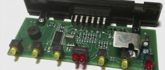
There are diagrams of homemade devices on the Internet. If you want to experiment, you can purchase an inexpensive amateur radio kit:
p, blockquote 39,0,0,0,0 –>
p, blockquote 40,0,0,0,0 –>
The connection diagram for such blocks is shown in a generalized form. You have to determine the specific wire routing yourself.
p, blockquote 41,0,0,0,0 –>
p, blockquote 42,0,0,0,0 –>
Video - UniKIT 2 connection diagram for Baltex tow bar:
p, blockquote 43,0,0,0,0 –>
p, blockquote 44,0,0,0,0 –>
It is also important to know 5 nuances about connection:
Figure 4. 5 nuances about connecting the towbar socket
Look at the towbar connector in the picture. Switching off will not be particularly difficult, especially if there is a universal component element, which is a towbar connector. It is very convenient to make the connection if the plug and socket match the connectors. Accordingly, a seven-pin socket must be connected to a seven-pin plug. In this option, you can make a normal connection, do not forget to combine the required sockets with the corresponding sockets.
Figure 5. 7 pin Figure 6. Cover
First familiarize yourself with the location of all seven connectors. If they coincide visually, then you can simply try to connect one to the other. If the towbar socket is of high quality, then it must have a cover. It is needed to protect against various external influences. Such protection will be required at a time when the towbar is not connected to the trailer.
Figure 7. Splicing
You can connect electronics in a simpler way. To perform such an operation, it is necessary to combine several leashes into a group and create an effective symbiosis of the supply of electrical signals. You can splice the contacts of two headlights, reverse lights, brake lights, fog lights and side lights. This is explained by the fact that when operating the car they will be used synchronously. Fastening is provided using brackets.
The next method involves changing the car's electrical system. This change consists of combining several wires that lead to the rear light and signal electrics of the trailer. They must be connected to the wires from the coupling device. If the vehicle has a complex electrical circuit, then you will have to spend a little more effort than in previous options. If the car's signal and light bulbs work without a special microprocessor, then you can connect a 7-channel towbar connector. Before you begin the operation, you should make sure that there are enough wires. If necessary, you can make the wiring elements yourself using a three-core copper wire of one and a half millimeters. They should be marked “PVS”.
If the connection is made directly, you must have a diagram of the towbar in front of your eyes, as well as a diagram of the car socket.
Towbar socket
To make the connection correctly, you need to supply turn signals, brake lights, as well as side and fog lights via one wire; you also connect license plate lighting there. You will also need to connect several wires that go to ground, the reversing light, if there is one. A special adapter is also installed on the electronic units. We are talking about a coordination unit between the electrics, the towbar and the towed part of the car. If there is such a connection, all connected parts will work smoothly and will not create problems for the motorist. Connecting the towbar coordination unit is done by yourself.
Photos of towbar connection diagrams will always help in your work if difficulties arise.
Connecting a trailer socket
The procedure for carrying out electrical installation work when connecting the towbar socket
p, blockquote 45,0,0,0,0 –>
1. First stage of work: determining the connection diagram, the need to use a matching unit, choosing the type of connector
.
p, blockquote 46,0,0,0,0 –>
If at the time of installing the trailer connector, the latter is not yet available, or you do not plan to buy it at all, and you intend to use only rental equipment, it is recommended to immediately install a 13-pin universal connector.
p, blockquote 47,0,0,0,0 –>
Video - why a 13-pin socket for a towbar is preferable in some cases:
p, blockquote 48,0,0,0,0 –>
p, blockquote 49,0,0,0,0 –>
In this case, using a 13/7 pin adapter, you can connect a regular cargo trailer without any problems.
p, blockquote 50,0,0,0,0 –>
p, blockquote 51,0,0,0,0 –>
There is, of course, the opposite option - a 7/13 adapter, but some of the user connections, including for charging the battery, will have to be made outside the connector, which is very inconvenient.
p, blockquote 52,0,0,0,0 –>
p, blockquote 53,0,0,0,0 –>
If you have a car built before 2000, you may not need to install a matching unit. In this case, the rating of the fuses serving the turn signals and rear lights should be increased by 25%.
p, blockquote 54,0,0,0,0 –>
2. Next, it is imperative to check all electrical circuits in the trailer connector
(if available).
p, blockquote 55,0,0,0,0 –>
This can only be avoided if you are using a rental trailer; the lessor checks them and is responsible for their functionality and safety.
conclusions
Now all that remains is to properly connect the trailer to the car and enjoy the result. If you notice a new type of socket or a complete disappearance of the models shown here from the shelves, please let us know. And don't forget to share the article with your friends!
Sources
- https://PricepInfo.ru/spravka/raspinovka-rozetki-farkopa/
- https://AutoTopik.ru/jelektrika/kak-podkljuchit-rozetku-pricepa.html
- https://www.asutpp.ru/raspinovka-rozetki-farkopa-pricepa.html
- https://pricepclub.ru/remont-i-obsluzhivanie/podklyuchenie-rozetki-pritsepa-legkovogo-avtomobilya
- https://avtoshark.com/article/repairs/electronics-repairs/podklyuchenie-rozetki-farkopa-k-avtomobilyu/
- https://elektro220v.ru/oborudovanie-dlya-avto/shemy-podklyucheniya-pritsepa.html
- https://DriverTip.ru/zhizn/pravilnoe-podkljuchenie-rozetki-pricepa-legkovogo-avtomobilja.html
Very useful tips
The headline may be loud, but in fact it is true.
All the diagrams presented above are intended for cars that do not have complex electronics.
But don’t forget that modern cars have come a long way. Modern cars have in their design such a device as an electronic control unit. When you turn on the ignition, the ECU goes into testing mode for all circuits in the car. When connecting a trailer, the load on certain lines increases. Your on-board computer, that is, the control unit or ECU, will perceive this as a breakdown. And as a result, you will constantly see an error. In such conditions, you should not count on normal operation of the trailer.
To correct this situation, you need a special adapter or module, whatever you call it. It is mounted as if in the gap between the elements in order to level out the parameters of the electrical circuit. It is called a matching block or, more modernly, Smart Connect.
As a result, we get something similar, as shown in the image below.
Finding a suitable matching block is not a problem at all. Nowadays there are a huge number of them available from different manufacturers. But I strongly do not recommend buying used modules or looking for them at various flea markets.
The blocks are selected based on what kind of trailer you have and the make of the car, as well as what towing device the car is equipped with. Otherwise, you may buy something incomprehensible that you will have to return and buy a normal connector.
An experienced auto electrician can connect everything without a diagram. A multimeter is used for this. But that's a completely different story.
Well, I hope I was able to answer many of your questions. If not, write in the comments and ask.
