Why do you need DPKV?
The crankshaft position sensor is necessary to determine the location of the pistons, namely when they are at TDC. This is necessary to supply a spark to the combustion chamber and ignite the fuel-air mixture.
The sensor operates on the Hall effect. The DPKV is connected to the crankshaft pulley, which has a crown with one missing tooth and helps determine the TDC sensor.
There is a magnet inside the sensor, which is a sensitive element and helps to read readings from the pulley. As soon as the magnetic connection between the sensor and the pulley is lost and the ECU receives a signal that it is necessary to apply a spark to the cylinder, which is now at TDC.
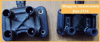
What happens if the crankshaft sensor on a VAZ 2114 is faulty
If the crankshaft sensor malfunctions, not very pleasant things can happen to the car.
- It may start to twitch, trip, stall at idle.
- Also, if the sensor is faulty, the car may seem to be driving normally at first glance, but if you look at the fuel consumption, it will be much higher.
This happens because the electronics are unable to sense the ideal timing of spark and fuel. Therefore, whenever possible, it is better for motorists to carry a spare DPKV sensor with them. It is not expensive, 200-400 rubles, depending on the manufacturer.
Reasons for failure
Sensor failures can be attributed to several reasons due to which the sensor most often fails.
- Time factor;
- Mechanical damage;
- Damage to the power circuit;
- Magnet contamination;
- Pulley damage;
Now more about each reason.
- Time factor. The main reason for the failure of the DPKV is its aging; the sensor is located very low, which quite often exposes it to humidity, dust and dirt. Such impacts damage the sensor connector and its magnet.
- Mechanical damage. As mentioned above, the sensor is located very low, which exposes it not only to contamination, but also to damage. When driving on country roads, stones or the like may enter the sensor. items. The sensor can also fail due to damage to the crankshaft pulley.
- Damage to the power supply. A special shielded wire is used to power the sensor, which helps remove interference generated during engine operation. Quite often, the sensor’s power cable becomes frayed or its insulation dries out over time, which leads to interference in the power circuit or even to its breakage.
- Magnet contamination. A magnet tends to attract any metal shavings, and when working with rubbing parts, these shavings are inevitable. Quite often, a large amount of metal shavings adheres to the sensitive part of the sensor, which dulls the sensitivity of the sensor.
- Pulley failure. The pulley is involved in the operation of the sensor and its curvature or separation from the damper can lead to improper operation of the sensor.
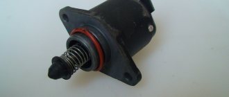
Antifreeze temperature sensor
To measure the exact temperature of antifreeze and control engine temperature conditions, the VAZ 2115 system has a DTOZH
Serves to control the temperature conditions of the engine, measures the actual temperature of the antifreeze. The coolant temperature sensor is a simple thermistor, that is, an element that changes resistance synchronously with the temperature of the antifreeze. The thermistor operates according to a negative coefficient algorithm; the higher the temperature, the lower the output resistance.
How to check
The coolant temperature sensor can be checked using a conventional tester, any device for measuring temperature up to 100-130 degrees, or a container of water. The multimeter is switched to resistance measurement mode, connected to the DTOZh terminals, and the sensor itself is immersed in a vessel with water. The vessel is heated, while the nominal resistance at 5 degrees should be within 7280 Ohms, at 20 degrees the coolant temperature sensor should produce 3520 Ohms, 40 degrees corresponds to 1458 Ohms, and at the boiling temperature the readings should not be higher than 90-100 Ohms. If the device readings do not correspond to the nominal value, the VAZ 2115 temperature sensor is replaced.
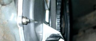
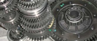
Pulley failure
The pulley affects the operation of the sensor and, therefore, the operation of the entire engine as a whole. Its curvature can lead to incorrect readings and, as a result, improper operation of the engine.
There are two types of pulleys: cast and with damper. A cast pulley is more reliable and durable, but the second type of pulley with a damper rubber insert is often damaged.
One of the most common failures of this pulley is the rotation of the crown relative to the crankshaft. Such a breakdown leads to displacement of the crown and incorrect determination of TDC by the sensor.
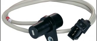
Types of crankshaft sensors
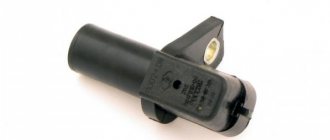
Inductive
inductive
Inductive (electromagnetic) inside have an iron rod wrapped with copper wire. This is the most common type of sensor. If a metal part (crankshaft pulley) appears near the rod, it reacts to its magnetic field, as a result of which its electromagnetic signal changes, which is fed to the electronic control unit. The concept of inductance itself is the extraction of energy from an electric current and storing it in another form.
The difference in signals before and after the passage of the crankshaft pulley is transmitted to the copper winding of the rod and an alternating current is generated on it. The winding itself is routed to a connector located on the DCPV housing. From the chip there are wires connecting the device to the control unit and the engine. The resulting alternating current is transmitted to the “brains” of the fourteenth, which determine the current position of the crankshaft. This type of sensor is considered more reliable and simpler than its counterpart.
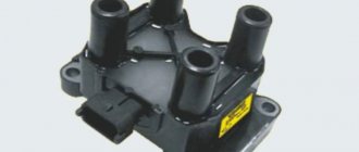
Frequency
frequency
The design and operating principle of the frequency-type crankshaft sensor is more intricate. Such devices also have an electromagnetic rod, but they are equipped with a converter operating on the Hall principle, which generates a frequency pulse from the resulting alternating voltage.
Information is supplied to the ECU in the form of pulse signals, similar to an electromagnetic sensor. Among the disadvantages of this device are the excessive susceptibility of the device to electromagnetic interference occurring in the circuit, and the presence of an electronic circuit in it reduces its reliability.
The principle of operation of the sensors is the same, but their devices are slightly different. The first sensor has become more widespread due to its simpler design.
Examination
The check must be carried out both externally and using diagnostic devices. Sometimes just a visual inspection is enough to determine the problem, so let's start there.
Sensor check
This is done by checking the sensing element for contamination. If the sensor magnet has a lot of chips on it, this indicates that it is not working properly. The sensor must be cleaned and reinstalled.
Next, the connector and power circuit are checked and there should be no traces of carbon deposits, rust or other types of damage.
Pulley check
The pulley must be inspected for its integrity and evenness.
Instrument testing
Such a check can only be carried out using special diagnostic equipment. Diagnosing DPKV in this way will be effective only when the check light on the car’s dashboard is on.
Symptoms of a problem
A malfunction of the crankshaft sensor leads to unpleasant consequences for the car:
- at idle speed the car may stall;
- tripping and jerking are noted during movement;
- fuel consumption increases significantly, since the electronics do not provide optimal supply of the fuel-air mixture and spark;
- traction weakens, the car refuses to start, or at idle the speed either rises or falls;
- the operation of the injectors responsible for fuel injection is disrupted, the operation of the ignition system changes;
- an indication appears on the dashboard.
Injecting a fuel-air mixture that does not coincide with the appearance of a spark leads to consequences that are difficult to predict.
In some cases, the symptoms observed by the car owner coincide with how the car behaves when the oxygen sensor fails. When the car does not have an on-board computer capable of indicating a possible malfunction with an appropriate indication, a sensor check is required. The car enthusiast can do it himself or go to the nearest service station.
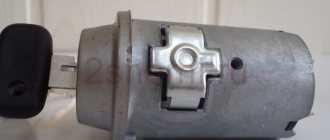
Replacement
Replacing the sensor is a fairly simple job that even the most distant person from cars can handle. The job involves unscrewing one screw and removing the connector from the sensor.
It is best to carry out work from the inspection hole, but if there is none, then replacement can be done by removing the front right wheel.
Let's start replacing
- Remove the connector from the sensor
- Unscrew the fastening bolt using a 10mm wrench
- We take out the sensor. This may be difficult to do, but since we no longer need the old sensor, we can take it with pliers and turn it in the mount.
- Install the new sensor in reverse order.
Remove from the engine
If a malfunction is determined, an urgent replacement of the crankshaft sensor on the VAZ 2114 is necessary, because there is no point in repairing it.
There are no difficulties here - just follow the instructions:
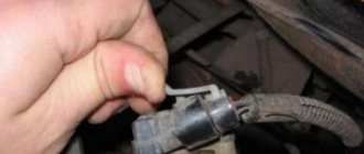
- Turn off the ignition and open the hood. Inspect the mounting location of the DPKV. If there are oil stains, they should be removed with a napkin or brush soaked in gasoline or alcohol. By the way, where is the DPKV located? It is located on the oil pump housing. You need to look for it in the upper right corner.
- Carefully remove the block with wires.
- Take a 10mm spanner and unscrew the fixing bolt.
- Now it can be removed. All that remains is to buy a similar DPKV for the VAZ 2114 with 8 valves (not 16!).
It is advisable to clean the sensor seat again. There may be oil stains that need to be removed with a cloth soaked in gasoline.
Installation is carried out in the reverse order, where you should also be careful:
- The tightening torque of the fixing bolt is clearly specified by VAZ regulations. It should be in the range of 8-12 Newtons. For this it is better to use a torque wrench.
- The distance between the crankshaft and the sensor should be about 1 mm, with a tolerance of 0.4 mm. If the distance is violated, the sensor will record the movement incorrectly. A special reference probe is used for alignment.
- Observe the pinout of the block. Incorrect connection of the chip can burn the new sensor, so it is important to maintain the connection. You can take a photo of the block or use the diagram.
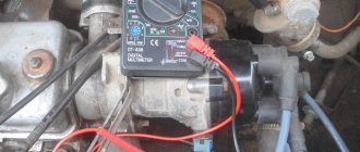
Input impedance measurement
The easiest way is to check the dpkv with a multimeter and measure the resistance of its winding. To do this, you need to have an appropriate device that can cope with this. If there is no such device, then you will have to resort to amateur radio. So, having switched your multimeter to resistance measurement mode and set the limit switch to 2 kOhm, securely install the probes of the device onto the sensor contacts, and they must be clean.
To achieve this, you can wash it with alcohol or gasoline. This may be the cause of the problem. Having installed the probes on the contacts, we observe the readings of the device, which should fit into the range from 550 to 750 Ohms. If this is the case, then the sensor is most likely working. But this can be stated with a probability of 50%, because during breakdowns and short circuits the resistance may change. And if the new one had 750 Ohms, and when checked it turned out that it was 500 Ohms, then this means that it is faulty. And he had an interturn short circuit.
This leads to a decrease in the pulse level that is detected by the controller. Therefore, to be sure of its 100% serviceability, you need to refer to the passport data, which will indicate its exact resistance and inductance. Based on this, you can check the inductance of the sensor winding. To do this, you need to switch your device to inductance measurement mode, if of course there is one. The readings on a working sensor should be up to 400 mH with a resistance of 750 Ohms. If, according to the passport, the sensor has a resistance of 500 Ohms, then accordingly its inductance will be 200 mH. If so, then the sensor is working.
In addition, the condition of the sensor insulation should be checked. To do this you need to have a megohmmeter. Although the multimeter has a mode for measuring high resistance, it is measured with low voltage and high error, while the megohmmeter produces voltage up to 500 V and is a separate device. So, having set the measurement voltage on the device to 500 V and the measurement accuracy to 10% under normal conditions (20-22 0), we place one end of the probe on the sensor body, and the other on the contact. The resistance should not be less than 20 MOhm.
Using an Oscilloscope
This method is the most reliable and with its help you can be 100% sure of the current state of the sensor. To do this, you need to turn on the oscilloscope to a limit of 10 ms and an amplitude of 1 V/div. And try to start the engine with the starter. In this case, on a well-charged battery, the engine should be accelerated by the starter to 800 rpm, this will correspond to a frequency of 200 Hz and a corresponding period of 5 ms/div. You should observe impulses, one period of which occupies two cells.
Source
AC voltage measurement
Checking the VAZ 2114 dpkv by measuring the variable component of the output signal is as follows. In order to measure the alternating component of voltage, it is necessary to ensure the appearance and absence of metal at its sensitive surface with a frequency of at least 200 Hz. To do this, you can use an auxiliary motor with a disk and a slot or protrusion, depending on the type of sensor. And power the sensor winding with a constant voltage of 1 or 2 V. Then switch the multimeter to the voltage measurement mode with a limit of up to 2 V of the alternating type. Next, you need to take a capacitor with a capacity of at least 1 μF and connect it to one of the terminals of the crankshaft position sensor, and the other end to one probe. Place the second probe on the second contact of the coil and turn on our resulting stand. Voltage should appear on the device readings when the disk rotates, this indicates that it is working properly. But, unfortunately, you will not see this voltage rating in the passport data. Because it depends on the selected capacitance, the more you increase it, the closer the readings will be to the supply voltage.