The ignition module on the VAZ 2114 8-valve injector and on other VAZ models is designed to supply high voltage through the PVN to the spark plugs. Some car owners call the ignition module a coil, which is not entirely correct.
Ignition coils were installed in carburetor vases. The VAZ 2110-15 uses the ignition module. Let's look at the functions of the ignition module, operating principles, circuits, and signs of malfunction.
Replacing ignition module 2114
It all started 2-3 months ago. I went on some errands, started it, warmed it up, sat down and drove off. I drive about 300 meters and the check light flashes... the engine seems to be running on 3 cylinders... basically I stopped and turned it off (what the hell did I say to myself)... With the emergency lights I barely made it home, parked the car and went to the store. I bought new NGK spark plugs and BB wires, installed them and started them, but it was like the car was spinning. Okay, I went for diagnostics while I was driving and the check went out and everything was fine. I did the diagnostics - they said there were no problems... Hmmm... Okay, I'm driving for another week... I went to a car service center (Near the house)... I arrived and I say such things... I measured the compression, in all pots there are 12, measured the pressure in the fuel rail - everything is fine, I adjusted the valves at the same time... The car started up and still rattled... I went home upset.
I gave up on the car - it drives and drives while it drives, “I said to myself,” and drove for another week... On the weekend, having collected my thoughts and spirit, I decided to go to the service center again. This time they cleaned the throttle, injectors, replaced the IAC sensor, and What do you think, what do you call sausage...
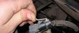
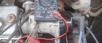
While sitting at work, I thought maybe it was connected to the ignition module... and it started dripping in different directions... I came across an article where they check the ignition module using a multimeter. I read in the article that the resistance between contacts 1 and 4, 2 and 3 should not exceed 5.8 kOhm
, Having found a multimeter at home.
Multimeter
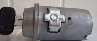
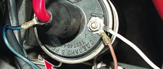
I went to the car, removed the ignition module by unscrewing 3 bolts and began to measure the resistance... and then it turned out that the module was long overdue for replacement...
Resistance between 1 and 4
Resistance between 2 and 3
Horrified, having installed the module, the store went back. Upon arrival at the store, they offered me a choice of 2 reels, one of them made in Russia and the other made by Bosch Germany, the difference in price was a little more than 1000 rubles... At that time there were problems with finances, so I had to buy something cheaper.
Having put the new module in place, the car simply whispered (I made 3 laps around the area with pleasure).
System replacement
If repairs fail to restore the device’s functionality, you will need to replace the module with a new one. At the same stage, you can move the module to another location, but we do not recommend doing this. When replacing, experts usually recommend using GM devices - these modules have proven themselves to be reliable devices. As for the price, it may vary depending on the country and region of residence, but on average it varies around 30-35 dollars or about two thousand rubles. More detailed and visual instructions for replacing the ignition coil along with high-voltage wires are shown in the video below (the author of the video is the STO TONN channel).
The replacement procedure can be done with your own hands; usually this task does not cause difficulties for motorists, and no specific tool is needed for this. All you need is a new block, a set of wrenches and rags. In general, the replacement procedure can be carried out in the garage or directly on the street.
If you do not know how to remove the ignition module and change it taking into account the pinout, then follow these steps:
- First you need to open the hood and turn off the power to the on-board network; to do this, disconnect the battery. It is not necessary to remove it, you can simply disconnect the negative terminal.
- Next, dismantle the high-voltage cables from the installation site, while marking their location separately on the sheet so as not to confuse them later, or put marks. Please note that you cannot change the seat wires, as this may lead to breakdown of the new module that will be installed in place of the old one.
- Then disconnect the wiring connector from the unit itself; for this you will need a 13mm wrench. Using the wrench, you need to unscrew the nuts securing the device to the engine.
- After unscrewing the nuts, the module can be dismantled. Using a rag, wipe down the installation area and the area around it. Check the new unit for damage, after which you can install it. The installation procedure is generally similar to the removal process, only done in reverse order. When installing, do not forget to connect the high-voltage cables correctly. If you have any difficulties at this stage, look at the module cover - the wire numbers should be marked on it.
Sorry, there are no surveys available at this time.
Checking the ignition module of a VAZ-2114 car with a multimeter
Internal combustion engines require fuel and an igniter to operate. The ignition module plays this role on fuel-injected cars.
The article will describe checking the VAZ-2114 ignition module with a multimeter.
The purpose of the ignition module (IM), operating principle, and main malfunctions will also be described in detail.
How to replace the ignition module yourself
In previous articles, we already figured out what an ignition module is, its operating principle, and its main malfunctions. I repeat once again that the module and the ignition coil are, in principle, different devices, but when we talk about them, we mean them as the same device with different names. Let me remind you that the ignition coil differs from the ignition module in the absence of a switch in the latter, which has moved to the ECU.
In this article we will talk about how to replace the module, namely, we will talk in detail about how to remove and install the ignition module.
This article will be useful to you not only for replacing the module, but also for removing the box, draining the coolant, replacing the thermostat, and for checking and repairing the ignition module.
We don't need many tools for this job. All we need is a pair of keys: a socket one at “13” and one at “17”. Well, don’t forget about “10” to remove the negative terminal of the battery. We also need a hexagon at “5”.
Purpose and principle of operation
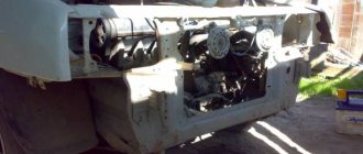
The ignition module of a VAZ-2114 car with an injection 8-valve power unit is located directly opposite the engine block on the spark plug side. This arrangement is most effective for supplying high-voltage wires to the spark plugs. The device is mounted on the wall of the engine compartment. This position was not chosen by chance. This way the MH interacts less with vibrating parts of the car.
The device that comes with the described car model is of the block type. One housing contains 2 inductors and 2 discharge voltage regulators. The device operates according to the following principle:
- A pulse signal passes from the crankshaft position controller to the on-board computer.
- The signal is confirmed by a pulse signal from the Hall sensor of the ignition system.
- Both signals are calculated in the on-board computer and transmitted as current to the module.
- The module converts 12 volt voltage into high current.
- From the coil, the voltage is supplied to the spark gap, which forms a pulse voltage.
- The voltage passes through the high voltage wire of cylinders 1 and 4 to the spark plug.
- The spark plug is discharged by a spark, igniting the fuel in the cylinder.
- During the discharge, spark plugs 2–3 also receive voltage, but its power is adjusted by the spark gap.
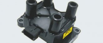
All components are made of high-strength plastic with an aluminum plate for mounting to the engine. Additionally, both coils are filled with insulating solution. On the body of the device there are only 4 contact sockets for high-voltage wires and an electrical power socket.
Subject to all operating rules, the ignition module is a very reliable electronic device, but it is quite fragile. If the electrical circuit has a number of damages and is often subject to short circuits, then the coils or arresters fail.
Any malfunction of the MH leads to interruptions in engine operation. The following will describe the main symptoms of a malfunction of this device.
Ignition module VAZ 2115 - check, malfunctions and replacement
To begin with, I would like to note that the ignition module on the VAZ 2115 is a fundamentally new device that is more reliable than what was installed on earlier models of VAZ cars. The essence of the operation of this device is that it produces a high voltage electric current, which is subsequently transmitted to the spark plugs of the vehicle’s ignition system.
Operating principle of the ignition module
As mentioned earlier, the main task of the ignition module is that it generates a high level of voltage, which is subsequently transmitted to the spark plugs. The generated current undergoes a compression procedure, as a result of which a working spark is supplied to one of the spark plugs of the ignition system, and an “idle” spark is supplied to the second. To be more correct in statements, the working spark is supplied to the first and fourth spark plugs of the vehicle’s ignition system, and the “idle” spark is supplied to the second and third. Thanks to this high-voltage electric current supply system, the spark appears at the right stroke and on the right cylinder, which ensures stable operation of the system.
Power to the VAZ 2115 ignition module is supplied directly from the vehicle’s on-board electrical network. The voltage supplied to the ignition module is twelve volts. At the same time, you should know that the negative wire of the ignition module is attached directly to the vehicle body. Design of the VAZ 2115 ignition module
The vehicle ignition module consists of a housing made of plastic, a pair of electronic control units, a pair of high-voltage current transformers, and four outputs for BB-type wires. Dimensions of the VAZ 2115 ignition module: one hundred ten by one hundred seventeen by seventy. The weight of the ignition module is one kilogram, three hundred and twenty grams.
Operating principle of the ignition module
The supply of electric current is carried out using wires of the BB type; the supply of electric current is controlled using a special controller, which makes decisions based on information that comes to it from various sensors of the vehicle. Also, the controller’s tasks include setting the sequence in which the ignition coil operates.
The ignition module can carry out its uninterrupted operation at temperatures from minus forty degrees to plus one hundred and thirty degrees Celsius.
What are the signs that indicate a faulty ignition module?
There are several typical signs that directly indicate problems with the ignition module:
1. The engine idle is floating. 2. Engine thrust periodically disappears for no reason. 3. The car picks up engine speed very slowly when accelerating. 4. The cylinders stop working in pairs.
Note that the same signs indicate a malfunction of the BB wires and spark plugs of the vehicle’s ignition system, so in the beginning, you should check them, and if everything is fine with them, then replace the ignition module.
Tools you will need:
To replace the ignition module on a VAZ 2115 car, you will need very few tools:
1. Open-end wrenches for seventeen and thirteen. 2. Ten socket wrench. 3. Hexagon.
Replacing the ignition module on a VAZ 2115 with your own hands
To independently replace the ignition module on a VAZ 2115, you should strictly adhere to a certain sequence of actions, which you can find below:
1. First, you must find the ignition module itself in the engine compartment. This can be done by following the high-voltage wires that come from the spark plugs of the ignition system.
2. Next, you must disconnect the negative cable from the battery.
3. Now, you need to remove the block to which the wires are connected from the ignition module.
4. Next, you should disconnect the high-voltage wires.
5. Now, you can unscrew the mounting bolts that secure the ignition module to the engine and remove it.
6. Then all you have to do is mount the new ignition module and assemble the entire structure in reverse order.
Malfunctions
During the operation of the car, problems arise in the operation of the engine. They are often associated with interruptions in the ignition system. The main symptoms are as follows:
- The appearance of code P0351 indicates the absence of a spark on the spark plugs of the first stroke.
- Error P0352 indicates a lack of spark on the second stroke candles.
- Codes P3000, 3001, 3002, 3003, 3004 indicate a missed discharge to the spark plugs.
In these cases, the power unit operates with a loss of power, and stability at idle speed is lost. The engine stalls during a sharp start, or when engaging any of the gears. Heating also increases and fuel consumption increases significantly. If there is no ignition, the smell of unburned gasoline appears. It becomes almost impossible to start such an engine. Such symptoms require immediate intervention and checking the VAZ-2114 ignition coil.
Why does the ignition module often fail?
Main sources of malfunction:
- The engine has spark plugs that do not meet the specified parameters. The gap does not meet the manufacturer's requirements. Excessive contamination of the spark plug contact, presence of carbon deposits. A visual inspection will help prevent parts from malfunctioning.
- The ignition coil operates when the high-voltage wire is disconnected. In this case, the engine may not operate correctly.
- If the device is not sufficiently secured to the motor body, then excessive vibration will eventually lead to failure of the coil. The internal soldering of the equipment is broken, which leads to a malfunction of the module.
- Poor contact of low-voltage wires can also cause a malfunction of the ignition system.
- A defective module has been installed. You may not notice this right away, but after a certain time the module will make itself known. Such parts cannot be repaired; it will have to be replaced with a new one.
- Condensation appears inside the module housing, which leads to a short circuit in the system and its failure.
Source
Examination
Often problems with MH begin after replacing high-voltage power wires. Many people may simply make a mistake by mixing up the connection points to the candles. The pin numbering scheme is presented below.
Also, owners of the injection-type VAZ-2114 often replace the standard wires with modern silicone analogues. This is absolutely impossible to do. Silicone high-voltage wires have significantly higher resistance. When replacing, it is also important to consider the length of each wire. Standard wiring has the following parameters:
- The wire of cylinder 1 has a length of 56 cm and an operating resistance of 2.5 to 3.8 Ohms.
- A 44 cm long wire with an operating resistance of 2 to 3 Ohms goes to the second cylinder.
- 3 wire 36 cm long, resistance from 1.6 to 2.6 Ohms.
- 4 wire 32 cm long, resistance from 1.4 to 2.1 Ohm.
This is worth considering, since high resistance significantly reduces the spark discharge current.
Also, a problem with the ignition module may arise due to problems with the fuse responsible for its protection. The fuse is located behind the cover under the dash on the front passenger's side. This is the very first fuse located between relays 1 and 2. The element should be checked for the presence of a working jumper inside the housing. The test can be carried out visually, or using a tester in dial mode. Be sure to replace the burnt-out protective element with a complete analogue, rated 15 amperes. It is also worth checking the incoming voltage. This requires:
- Set the tester to DC voltage measurement mode up to 20 volts.
- Connect the red test probe to the fuse terminal.
- Connect the black probe to ground.
- Turn on the ignition.
The voltmeter should give a reading equal to the battery charge. If there is voltage, it means it is reaching the ignition module.
Module
Many owners of the car described do not know how to check the VAZ-2114 ignition module using a multimeter. First you need to test the device with the engine running. This requires:
- Start the power unit.
- Ask an assistant to keep the speed within idle.
- Wear a glove or take a dry cloth.
- Remove the power wires from the module sockets one by one.
Each removed wire must be brought to the power unit block. Without touching, a spark should discharge from the tip. A blue spark and a discharge accompanied by a crackling sound will indicate the necessary supply of discharge current. In this case, the engine should respond to the removed working wire by reducing the speed. If a wire is detected from which the spark does not come or it is quite weak, the engine speed will not change.
The previously described error codes from the on-board computer can also help in finding the wire with no spark.
For more effective testing, it is necessary to dismantle the ignition distribution device and carry out a test with a tester. This is easy to do if you follow these instructions.
First you need to dismantle the device. This is done as follows:
- Disconnect the ground terminal from the battery.
- Remove 4 high-voltage wires from the MZ sockets.
- Disconnect the electrical power plug.
- Unscrew the 3 nuts securing the module.
- Remove the device.
Next, a mandatory visual inspection of the device is carried out. The ignition module is a rather fragile device. The presence of defects on the housing, cracks and dents, can cause an internal short circuit. You also need to pay attention to the sockets for power cables. There should be no oxidation or dirt on the terminals. Any malfunctions should be eliminated by cleaning with a solvent. Next you need to check the connecting plug. Its contacts also need to be cleaned. Below is a step-by-step guide on how to check the VAZ-2114 ignition module with a multimeter.
Checking the connecting plug
First you need to check the incoming voltage to the module. This is done as follows:
- The multimeter is switched to voltmeter mode to measure DC voltage.
- The red measuring probe is connected to the incoming half of the module plug, with the central contact. It is he who is responsible for powering the device.
- The black test probe is connected to ground.
- Turn on the ignition.
The tester should show a voltage of 11.5–14 volts, equal to the battery charge.
Next, the incoming signal is checked. The voltmeter remains in the same position.
- The red probe of the tester is connected to contact “1” of the coming side of the plug. This contact is responsible for the distribution of pulse current for the cycle of candles 1–4.
- The black probe connects to ground.
- It is necessary to crank the starter a few turns.
The voltmeter should show pulse voltage. Contact “3” on the plug is checked in the same way.
Module plug
For this test, you need to switch the multimeter to resistance measurement mode. Next you need:
- Connect the red control probe to terminal “1”.
- Connect the black control probe to terminal “3”.
- The operating resistance should be within 0.5 Ohm.
In this way, both secondary windings of the ignition coils are checked. Any deviations in resistance will indicate an internal violation of the integrity of the winding.
Using the following test, the presence or absence of a short circuit is checked.
- The multimeter remains in resistance measurement mode.
- Connect the red test probe to the central contact of the plug.
- Connect the black test probe to the device body.
- The tester should not show any results. This will indicate that there is no internal short circuit. Any minimal resistance during this test is reason to replace the module.
The following check is needed to test the primary windings. The check is carried out as follows:
- The multimeter is switched to resistance measurement mode.
- Insert the red measuring probe into the “1” socket for high-voltage wires.
- Insert the black measuring probe into socket “4”.
- The operating resistance of the primary phase windings is 0.5 Ohm. Any data that differs from the nominal value can be recognized as the presence of an interturn short circuit in the primary winding of cylinders 1–4.
The test of sockets “2” and “3” is carried out in a similar way. Their operating resistance should also be 0.5 Ohm.
Additionally, you can check in the same way, but between sockets “1” and “2”. There are no internal connections between them. If there is resistance, the part is considered unsuitable for further use.
Symptoms of a problem
A large number of symptoms can be attributed to MH malfunctions, most often they are similar to a faulty spark plug and a malfunction of high-voltage wires.
If the following problems appear on your car, then most likely the ignition module is faulty:
- The engine is dual (two cylinders do not work at once) either 1-4 or 2-3. This is one of the reliable signs of a breakdown of the MH.
- The engine loses power and traction;
- When you press the gas pedal, jerks appear and the engine stutters;
- Difficulty starting the internal combustion engine when hot;
If such symptoms are detected on the car, it is necessary to check all the parts responsible for supplying the spark, spark plugs, wires and module.
Other reasons
If, after checking the ignition module of an injection-type VAZ-2114 car, no malfunction was identified, then you should pay attention to breakdowns or improper operation of adjacent devices.
- Powertrain control unit. It happens that after an electrical short circuit, the ECU loses its internal settings. To restore functionality, you need to disconnect the “+” terminal from the battery and connect it again. The ECU will enter a temporary reboot, and the module's operation may be restored. It is also worth carrying out professional diagnostics of the on-board network.
- Crankshaft position sensor. An important source of pulse signals. Its data affects the distribution of voltage from the ECU to secondary devices. It is necessary to check the functionality of this element, its wiring, and the protective fuse. If necessary, replace faulty parts.
- Hall Sensor. This device is responsible for the distribution of pulses. Signals are generated due to contact connection during rotation of the device rod. Any deviations in the supply of signals affect the operation of the ignition module.
- Generator. The high charge current of this mechanism often leads to complete burnout of the secondary winding of the MC. The first problem may be a faulty fuse. If such a problem is detected, it is worth checking the amount of voltage coming from the generator.
The system, which includes a Hall sensor, DPKV and ignition module, works by calculating the position of the crankshaft. This is how the exact order of the spark cycle on the cylinders is achieved.
Important! Very often, the performance of the MH is affected by careless operation of this device. The cause of failure may be:
- Lack of contact with the “mass”. This occurs when the 3 bolts securing the device are insufficiently tensioned. Periodic loss of contact leads to a break in the circuit. The newly appeared contact causes the discharge of a current of greater strength. This leads to internal burnout of the secondary winding of the coils.
- Lack of contact on spark plug caps. A poor connection leads to contact vibration, often high-voltage wires fly out and short to ground. This leads to damage to the MZ discharge contactor.
- Poor contact or oxidation at the battery terminals. It also leads to a short-term but powerful discharge of the primary winding.
- Spark plug gap. The manufacturer sets a fixed spark plug gap. The maximum value for spark plugs installed on injection engines can be 1.3 mm. A large gap leads to a spark hitting the housing. The spark is simply deflected to the side. A small gap size can lead to breakdown of high-voltage wires or the ignition coil itself. The high voltage pulse current is simply discharged back into the circuit.
Many car enthusiasts try to disassemble and repair ignition modules themselves. With proper knowledge of electronics, only the discharge regulator can be repaired. The coils will have to be rewound. But the main difficulty lies in the subsequent sealing and insulation of the inductors. Any remaining cracks will cause breakdown and failure. It is better to purchase and replace the MZ with an exact analogue.
Repair
Location of the VAZ 2114 module under the hood
Before going to a car dealership to buy a new module, it is recommended to check the device contacts. If they fail, you can do the repairs yourself and not spend money on a new module. To check, you need to start the engine at idle and try to press the module cover with an insulated tool. If the engine starts working normally, then the problem is in the contacts. The work is not difficult, but quite painstaking, and you will need skill in handling a soldering iron. For repairs, you need to stock up on small and thin wires, varnish, a soldering iron, a screwdriver and flux for soldering aluminum.
Process:
- You need to dismantle the device according to the instructions described above.
- Next, you need to remove the housing cover; to do this, press down with a screwdriver. If the device is not standard, there may be bolts there.
- On the board you can see whether the guesses are correct or not.
- If the contacts have come loose, then you need to strip the board of small wires and replace them with new ones.
- A problem may arise with transistor controllers - they are covered with a protective layer that the soldering iron does not take. It can be cleaned with improvised materials or a burr machine.
- Small wires need to be replaced.
- The final step is to cover the soldering areas with varnish or silicone. Even nail polish will do. That's all.
Ignition coil VAZ 2114 8 valves, VAZ 2113, VAZ 2115
Here we consider the ignition coil of VAZ 2114 8 valves, VAZ 2113, VAZ 2115 model 2111-3705010-02 (54.37005) with injection engine 11183 (l,6i). The ignition coil of the VAZ 2114 injection 8 valve engine is described. The diagram of the ignition coil of VAZ 2114, 2113, 2115 is shown. The electrical diagram of connecting the ignition coil of VAZ 2114 injector 8 is presented. Malfunctions of the ignition coil of VAZ 2114 8 valves are given. The pinout of the ignition coil for VAZ 2114 injector 8, VAZ 2113, VAZ 2115 is shown.
Connection diagram
The ignition module is part of the space under the hood, it’s easier to find it by the position of the high voltages, they go from the spark plugs straight to it.
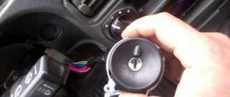
VAZ 2114 ignition coil diagram
This diagram is good to follow when you have to replace the ignition coil of a VAZ 2114. In principle, everything is transparent: from contacts with the controller (ECU) to high-voltage wires. The name of the circuit is often common under the name ignition coil pinout: the pinout is a visual representation of the functionality of the device's contacts, which are numbered according to their purpose.
Basically, the most necessary knowledge about what the pinout of the ignition coil is is carried by high-voltage wires (abbreviated as HF (contacts). Because it is through the HF contacts that, in fact, the ignition module is connected to the engine system.
It can be connected in two different ways: when the ignition system coil is removed and when it is directly in its place in the car engine.
If you are holding the module in front of you:
- Let us recall the diagram: the first and fourth contacts are on one winding, the second and third – on the other (they are numbered in the diagram!)
- Then, the lower explosive contact (left) goes to the first cylinder
- On the second - upper explosive contact (left)
- The third cylinder goes to the upper explosive contact (right)
- On the fourth – lower explosive contact (right)
If the module is plugged into the engine, then pinouting the explosive contacts will be more difficult, because the device stands at an angle (as if in a diamond):
- We throw the central lower contact onto the first cylinder
- On the second - left contact
- We put the upper contact on the third cylinder
- On the fourth - right contact
Of course, the first installation option is more convenient, especially since the explosive wires require increased care in the nature of the connection (mixed up and won’t start, in the worst case, the entire engine system is ruined). Speaking to the point, it is clear that the connection diagram for the VAZ 2114 ignition module is not complicated.
By the way, buying an ignition coil is not a cheap pleasure; the price of an ignition module for a VAZ 2114 ranges from seven hundred to a thousand rubles, depending on the location of your city on the map of our country (for more information about how much an ignition module for a VAZ 2114 costs, you can find out by calling a disassembly service or a spare parts store, the running part is almost always in stock).
Description and purpose
Ignition coil VAZ 2114 8 valves, VAZ 2113, VAZ 2115 are two two-output ignition reels mounted in a single casing. It is designed to convert low on-board voltage (12 volts) into high sparking voltage. Sparking occurs in two pots at once (1-4 and 2-3). The ignition solenoid is connected to the spark plugs by high-voltage wires with permanent tips.
| 1 — ignition coil VAZ 2114 |
| 2 - package of high-voltage wires |
Below, in the figure, the design of the ignition coil of the VAZ 2114 8 valves is presented
Necessary tool
To replace the ignition module on a VAZ 2114, no special equipment is required. To change a part, just prepare the following tool:
- Set of socket wrenches;
- Hexagon 5;
- Screwdrivers;
- A rag or rag.
The process of replacing the ignition module
The entire procedure is carried out on a horizontal surface in the garage or on the street. The procedure for replacing the ignition coil of a VAZ 2114 is as follows:
- Raise the hood and disconnect the battery. To do this, use a 10mm wrench, slightly loosen the nut securing the minus terminal, and remove it from the battery.
- We take out the high-voltage wires. Here it is important to remember (you can take a photo) where and which wire was connected. For your convenience, we have written a separate article about the order of high-voltage wires. It is strictly forbidden to swap wires so as not to damage the ignition module the next time it is turned on.
- Disconnect the four high-voltage wires.
- Using a 13 mm socket wrench, unscrew the nuts that secure the module to the engine.
- After removing the nuts, we dismantle the equipment.
- Unscrew the screw securing the coil to the motor using a hexagon.
- Next, the installation site of the coil should be thoroughly wiped from accumulated dirt. To do this, you can use a rag or a clean rag.
- We install new equipment in the cleaned area in reverse order.
- Correctly connect high-voltage wires. Their numbers must be indicated on the block.
Advice . To ensure reliable contact, the mounting of the coil and the motor housing should be thoroughly cleaned.
The principle of operation of the ignition coil VAZ 2114 8 valves, model 2111-3705010-02
The current in the primary windings of the ignition coils is controlled by a controller that uses information about the engine operating mode received from the engine control system sensors. To switch the primary windings of the ignition coils, the controller uses two powerful transistor valves.
From the ignition coil of the VAZ 2114 8 valves, a high voltage pulse is supplied to two cylinders at once: 1 - 4, 2 - 3. In one cylinder the compression stroke ends (working spark), and in the second the exhaust stroke (idle spark) occurs.
Due to the constant direction of current in the primary and secondary windings, the sparking current of one spark plug always flows from the central electrode to the side electrode, and the second - from the side to the central one.
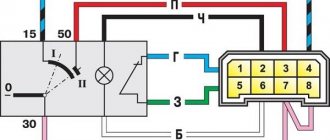
The ignition coil of the VAZ 2114 injector 8 valves works according to the following principle. The vehicle's electrical system voltage is supplied from the ignition switch to contact “15” of the ignition coil. Next, the controller switches the pulse to terminal “1b”, the circuit of the primary winding of the ignition coil, as a result of which the secondary winding outputs high voltage to the spark plugs of cylinders 1 and 4. And the controller switches the pulse to terminal “1a”, the circuit of the primary winding of the ignition coil, as a result which causes the secondary winding to output high voltage to the spark plugs of cylinders 2 and 3.
| Deciphering the engine ignition system with an ignition coil VAZ 2114 | |
| Position number on the VAZ 2114 diagram | Explanation of position |
| 1 | accumulator battery; |
| 2 | main relay; |
| 3 | ignition switch; |
| 4 | spark plug; |
| 5 | ignition coil VAZ 2114 8 valves model 54.37005; |
| 6 | controller; |
| 7 | crankshaft position sensor; |
| 8 | master disk. |
Symptoms of a faulty ignition coil
The module's task is to transmit voltage to the spark plugs through high-voltage conductors. In this case, the electronic control unit (ECU) controls the transmission process by sending charged pulses to the winding. As a result, a spark is formed necessary to ignite the fuel inside the combustion chamber.
If this circuit is broken, the engine will run intermittently, which will affect the safety of the car. There are several signs that make it clear to the car owner that the coil and the ignition system as a whole need to be checked:
- Insufficient engine power when accelerating the car;
- When you press the gas pedal, the car does not pick up speed, especially when overtaking;
- When the car is idling, the engine runs intermittently;
- The spark plug does not produce a spark.
Advice. When the first signs of a vehicle malfunction appear, the first thing you need to do is look at the spark plugs, then make sure the crankshaft position sensor is working, and only then move on to the module.
Explanation of the ignition coil designation (Catalogue number) - 2111-3705010;
The designation of a part or assembly is a unique number in a single form. Assigned to only one part. The numbering of designations for assembly units and parts is carried out according to a unified seven-digit system. Designation - 2111-3705010-02 is deciphered as follows. The first four digits before the dash indicate the model of the base car or engine, chassis, body. In our case: 2111 is the engine model. The first two digits after the dash indicate the group number, in this case 37 - electrical equipment. The next two digits are the subgroup number. In our case, 05 is the ignition coil. The last three digits of the seven-digit number indicate the serial number of the part. The last two digits after the second dash indicate the interchangeability of the part. ХХХХ-ХХХХХХ-00 (to-09) - interchangeable. ХХХХ-ХХХХХХХ-10 (up to 19) are interchangeable with each other but not interchangeable with ХХХХ-ХХХХХХХ-00 (up to-09) and so on.
The part designation is applied to the body of the part. It helps determine the interchangeability and suitability of a particular part when purchasing and searching for it.
Pinout of ignition coil VAZ 2114 8 valves model 2111-3705010-02 (54.37005)
The figure below shows the pinout of the VAZ 2114 ignition coil 8 valves model 2111-3705010-02 (54.37005). The arrows on it indicate the contacts and their purpose.
Schematic diagram of engine control with an ignition coil
| Deciphering the schematic diagram of engine control with an ignition coil VAZ 2114 | |
| Position number on the VAZ 2114 diagram | Explanation of position |
| 1 | ignition switch; |
| 2 | main relay; |
| 3 | battery; |
| 4 | atmospheric filter; |
| 5 | diagnostic connector; |
| 6 | dashboard; |
| 7 | tachometer; |
| 8 | check lamp; |
| 9 | speedometer; |
| 10 | immobilizer sensor with indicator; |
| 11 | immobilizer manual device; |
| 12 | electric fan of the engine cooling structure; |
| 13 | electric fan relay; |
| 14 | controller; |
| 15 | DTOZH; |
| 16 | ignition coil VAZ 2114 8 valves, VAZ 2113, VAZ 2115; |
| 17 | spark plug; |
| 18 | DPRV; |
| 19 | sprayers; |
| 20 | throttle assembly; |
| 21 | TPDZ; |
| 22 | DMRV; |
| 23 | empty control; |
| 24 | Lambda probe; |
| 25 | car speed sensor; |
| 26 | DPKV; |
| 27 | DD; |
| 28 | crankshaft pulley; |
| 29 | gasoline filter; |
| 30 | petrol pump relay; |
| 31 | gasoline tank; |
| 31 | gasoline unit; |
| 32 | two-way valve; |
| 33 | gravity throttle; |
| 34 | reverse breather; |
| 35 | check valve; |
| 36 | adsorber purge throttle; |
| 37 | adsorber; |
| 38 | separator. |
Ignition module diagram 2115
The circuit diagram and connection diagram of this electronic device is presented below.
The ignition module installed on the Lada Samara is extremely resistant to both low and high temperatures. Operating temperature range: -400/+1300C.
The only negative point in the operation of this electronic device is its complete inability to repair. However, even a novice car enthusiast can replace it on his own.
Experts consider the most common malfunctions of the Samara ignition module to be:
Unstable operation of the power plant when accelerating the vehicle.
Checking the ignition coil of a VAZ 2114 injector 8 valves
Checking the ignition coil of the VAZ 2114 model 2111-3705010-02 (54.37005) is carried out in the following sequence:
- Disconnect the terminal block of the ignition reel;
- Turn on the ignition, use a multimeter to measure the voltage between terminal 15 and the housing, for the ignition reel, or terminals C and D (for the ignition module) of the terminal block with a cable harness. The voltage must be at least 12 V. When the voltage does not go to the terminal block or it is less than 12 V, the battery is discharged, the power line is broken, or the controller is broken. You can verify that the ignition module is working by replacing it with a known working one. The ignition coil can be checked with an ohmmeter.
- Remove the ignition coil;
- Using a multimeter, we measure the electrical resistance between the middle terminal 15 and the bracket. The meter must indicate the absence of the short of the first winding of the solenoid on the housing. In order, we measure the electrical resistance between the middle terminal 15 and the outer terminal - 1a and 1b. The resistance of all the first windings of the bobbin must be around 0.5 Ohm. When we measure small electrical resistance sizes, about 1 Ohm, we need to take into account the internal resistance of the meter, which can be measured by short-circuiting the multimeter probes.
- Using a tester, we measure the resistance between the high-voltage terminals of the solenoid 1 and 4, and then 2 and 3. The resistance of the windings should be around 5.4 kOhm.