The ignition switch in cars of the VAZ family fails from time to time due to weakening of the contact posts or burning of the contacts inside it. It also happens that the cams of a plastic roller are produced. You can disassemble the lock and clean it, but it’s better to just replace it with a new one, considering that it costs pennies compared to imported locks.
But if connecting the wires together did not result in the starter operating (or it did not turn on the first time), check the solenoid relay on the starter. The contact spots on it may also burn out, which will prevent the circuit from closing normally. Alternatively, you can use a screwdriver to short-circuit the two large terminals on the solenoid relay (before doing this, put the car in neutral and use the handbrake). When closed, the starter should begin to spin vigorously. If this happens, remove and change the solenoid relay. If the starter rotates “sluggishly” when it closes, you will have to remove it and check the condition of the brushes.
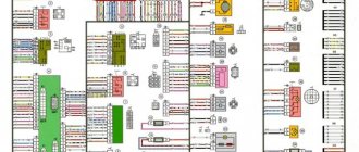
All operations are performed with your own hands, without the help of car service specialists. Moreover, the price of an ignition switch on a VAZ2106 is up to 100 rubles. To replace it, you will need to know the pinout of the wires coming from it, for which the editors of the site 2 Schemes.ru have prepared a large reference material.
The ignition switch is designed not only to start the engine - it performs several functions at once:
- supplies voltage to the vehicle’s on-board network, closing the circuits of the ignition system, lighting, sound alarm, additional devices and instruments;
- at the driver’s command, turns on the starter to start the power plant and turns it off;
- turns off the power to the on-board circuit, preserving the battery charge;
- protects the car from theft by fixing the steering shaft.
Pinout of the ignition switch VAZ-2101 - VAZ-2107
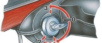
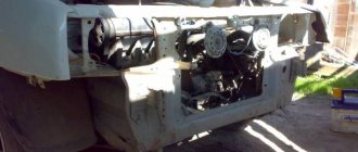
The ignition switch on these cars is located to the left of the steering column. It is fixed directly to it using two fixing bolts. The entire mechanism of the device, except for the upper part in which the keyhole is located, is hidden by a plastic casing.
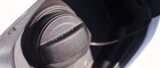
On the visible part of the ignition switch housing, special marks are applied in a certain order, allowing inexperienced drivers to navigate the lock activation mode when the key is in the hole:
- “” – a mark indicating that all systems, devices and instruments that can be turned on using the lock are turned off (this does not include the cigarette lighter, interior lighting, brake light, and in some cases the radio);
- “ I ” is a mark informing that the vehicle’s on-board network is powered from the battery. In this position, the key is fixed independently, and electricity is supplied to the ignition system, to the electric motors of the heater and windshield washer, instrumentation, headlights and light signaling;
- “ II ” – engine start mark. It indicates that voltage is applied to the starter. The key does not lock in this position. If you release it, it will return to the "I" position. This is done so as not to subject the starter to unnecessary loads;
- “ III ” – parking mark. If you remove the key from the ignition in this position, the steering column will be locked with a latch. It can only be unlocked by inserting the key back and turning it to position “0” or “I”.
The ignition switch has five contacts and, accordingly, five terminals, which are responsible for supplying voltage to the desired unit. All of them are numbered for convenience. Each pin corresponds to a wire of a certain color:
- “50” – output responsible for supplying current to the starter (red or purple wire);
- “15” – terminal through which voltage is supplied to the ignition system, to the electric motors of the heater, washer, and instrument panel (double blue wire with a black stripe);
- “30” and “30/1” – constant “plus” (pink and brown wires, respectively);
- “INT” – external lighting and light signaling (double black wire).
Main signs of failure
Drivers need to take into account during operation that breakdowns can occur both due to failure of the mechanical part and due to problems with the electrical system. Popular mechanical problems manifest themselves in the following factors:
- the lock is stuck in one position and there is no way to unlock it without using significant effort;
- the steering column is jammed;
- an attempt was made to gain unauthorized access to the lock using a master key or other object unsuitable for this purpose.
Pinout of lock VAZ-2108, VAZ-2109, VAZ-21099
Pinout according to the old type
Pinout of the VAZ-2109 ignition switch with unloading relay:
- comes +12V in position I, II, III (parking)
- comes +12V in position I, II, III (parking)
- comes +12V in position III (parking)
- position I, +12V goes out after turning on the ignition (contact 15/2), disappears at start (II);
- position I, +12V goes to the starter (pin 50);
- position I, +12V goes away after turning on the ignition (pin 15), does not disappear when starting II;
- +12V comes from the battery (pin 30);
- comes +12V constantly.
New pinout type
Pinout of the new VAZ-2109 ignition switch:
- comes +12V constantly
- comes +12V constantly
- +12V arrives after turning on the ignition (pin 15), does not disappear when starting II;
- +12V arrives after turning on the ignition (contact 15/2), disappears at start (II);
- position I, +12V goes to the starter (pin 50);
- +12V arrives after turning on the ignition (pin 15), does not disappear when starting II;
- +12V comes from the battery (pin 30);
- comes +12V constantly.
Preparation
It is necessary to prepare spare parts and other equipment for work. A new ignition switch will be needed. It is quite easy to find original parts and analogues on the Internet, but it is worth considering that it is advisable to purchase the lock “assembled”.
Catalog number of the original VAZ 2114 ignition switch: 21103704010. Approximate price: 500 rubles for a used part and 1200 for a new one.
As a replacement, you can use analogues with numbers: 09401, 24370407. Approximate price: 1000 rubles (new part).
In addition to the lock itself, you will need the following tools:
Before you begin, you must also remove the steering column cover and steering column switches.
Pinout of lock VAZ-2110, VAZ-2111, VAZ-2112
Pinout of the ignition switch VAZ-2110:
- comes +12V for the microphone of the sensor of the inserted key;
- the mass comes when the driver's door is open;
- +12V goes to the starter (pin 50);
- +12V goes out after turning on the ignition (pin 15);
- +12V goes out when the key is inserted to pin 5 of the BSK;
- comes +12V to illuminate the lock cylinder;
- +12V comes from the battery (pin 30);
- not used.
Useful: Diagram and pinout of fuse blocks for VAZ cars
In what cases is replacement required?
There are several situations when replacement of the seal is necessary:
- malfunction of the unit itself;
- loss of keys;
- mechanical damage to the protection during theft;
- contact group malfunction.
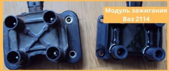
3Z device diagram
A unit malfunction can be detected when the engine starts. When the starter does not spin, the solenoid relay does not click, and electrical equipment does not work. Failures can be mechanical or electrical.
Pinout of lock VAZ-2113, VAZ-2114, VAZ-2115
Pinout of the ignition switch VAZ-2113, 2114, 2115:
- comes +12V for the microphone of the sensor of the inserted key;
- the mass comes when the driver's door is open;
- +12V goes to the starter (pin 50);
- +12V goes out after turning on the ignition (pin 15);
- +12V goes out when the key is inserted to pin 5 of the BSK;
- comes +12V to illuminate the lock cylinder;
- +12V comes from the battery (pin 30);
- not used.
Recommendations
Reassembling and lubricating individual parts will not work if the fragments are heavily worn. It is better to remove the cylinder from the core and install a new one. Recommendations for replacing the VAZ 2114 door lock:
- Partial repairs or lubrication will only temporarily restore life to the closing mechanism. If problems arise, it is better to replace the entire cylinder.
- After installation, it is necessary to periodically lubricate the mechanism. Experienced motorists use silicone substances for this.
- The repair procedure is carried out in a well-lit room at a comfortable temperature.
- To change the element, you will need a set of screwdrivers, pliers and lubricant.
- Sometimes the springs have to be replaced along with the cylinder. They are purchased separately.
The cylinder fragment is sold as a set. The price depends on the manufacturer. If you buy a cheap Chinese version, it will cost about 150 rubles. It is better to give preference to VAZ spare parts. The cost of such a kit is 400-500 rubles.
Withdrawal procedure
Depending on the reason, a complete or partial replacement is performed. It is not recommended for the average person to engage in reassembly, since there are too many nuances in this process, but almost anyone can replace the mechanism. Step-by-step instruction:
- Three screws are unscrewed. They are located on the inside of the handle. To do this, use a Phillips screwdriver to remove the cover.
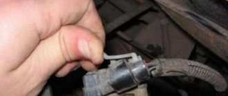
- The front trigger glass position switch is removed along with the wiring harness block. To do this, the wires are first disconnected.
- The plug on the armrest handle is removed, the element is picked up with a thin corner of a screwdriver.
- Unscrew the 2 screws on the handle that hold the inner panel.
- The plastic clips are pressed out to remove the lining.
- 6 pistons are removed to remove the door card.
- The external fastenings are removed, the nuts are unscrewed with an 8mm wrench.
How to remove cravings
To remove this piece, you will need an impact screwdriver and a size 8 wrench. The piece is attached to the internal locking mechanism and the lock switch. Algorithm of actions:
- The internal lock of the outer handle rod is completely disconnected.
- The handle is removed along with the rods.
- The pin is removed from the end of the rods.
- The plastic tip is removed from the core of the cylinder device.
- The return spring is removed. The old larva is being removed.
Installing a new part
The removal and assembly algorithm is the same, although the instructions for installing the cylinder mechanism have its own nuances. Before inserting a new cylinder into the core, the part is lubricated with a silicone substance and only then inserted into the handle. Further algorithm of actions:
- The return spring is inserted next to the cylinder.
- The functionality of the key is checked. It should turn easily in all positions.
- A pin is installed on the tip of the rotary rod. Connection is being made.
- The inner and outer panels are screwed on, the handles are fixed, and the plug is returned to its place.
- The main three screws are tightened from the inside.
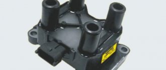
The structure of a car ignition switch
- Locking rod
- Frame
- Roller
- Contact disc
- Contact sleeve
- Block
- Protrusion of the contact part.
The lock mechanism is connected to many wires. They continue from the battery, connecting all the electrical devices of the car into a single chain. When you turn the ignition key, the electrical circuit is closed from the “-” terminal of the battery to the ignition coil. As a result, the current passes through the wires to the ignition switch, through its contacts it is directed to the induction coil, after which it returns back to the “+” terminal. As electricity passes through the coil, it generates high voltage, which it transmits to the spark plug. Therefore, the key closes the contacts of the ignition circuit, thereby starting the car engine.
Connection diagram
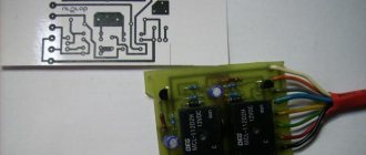
After carefully studying the alarm installation instructions, you can find the following connection diagram:
In this diagram, the designation X2 indicates a six-pin connector. It must be connected according to the diagram above. If you need to install an additional actuator, then it is better to use the diagram given in the instructions.
Now let's figure out how to connect the door sensors. For this purpose, there is a special wire in the connector marked X3.
Preparation
At the preparation stage, you will need to collect the necessary tools near you, which will be useful in the process of dismantling and installing a new ignition switch. You will also have to remove the steering cover and steering column shifters. Doing this is quite difficult, but we will tell you step by step about all the nuances of these preparatory activities. So you can easily figure out for yourself how to remove the ignition switch on a VAZ 2114.
Tools you will need:
- Phillips strong screwdriver;
- Open-end wrench 10 millimeters;
- Chisel;
- Hammer;
- Pliers or pliers;
- New ignition switch assembly;
- Lock mounting screws (4 pieces).
Now let's move on to the casing and switches. For more convenient work, many advise removing the steering column switches and the steering wheel itself. Dismantling the casing is performed in the following sequence:
- Disconnect the negative cable from the battery. Nobody has yet canceled the requirements for personal safety and protection against electric shocks;
- Unscrew the three screws securing the two parts of the casing. A screwdriver is useful for this;
- Unscrew the screw that connects the housing to the connector of the steering column switches;
- Remove the two screws that hold the lower housing to the steering column;
- The lever that fixes the column at the corner leads down;
- The steering wheel also goes down;
- The lower casing is then removed;
- The power supply from the emergency lights must be disconnected;
- Now you can remove the top casing;
- To dismantle the steering column switches, you need to act one by one;
- Simultaneously press both latches and thereby remove the elements from their seats;
- Disconnect them from the power supply.
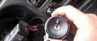
Steering lock testing
If you don't check the steering lock, you may encounter certain problems in the future. Therefore, do not waste your time on this event. It consists of removing the key from the ignition and turning the steering wheel at a slight angle.
- If there is no lock, you will need to slightly adjust the position of the lock. Make sure it fits into the groove located on the steering shaft.
- If the locking is effective, you will only need to tighten the four installed breakaway bolts until they stop. Twist until the heads break.
When the lock installation is completed and the test has passed, do not forget to connect the device to power and start the engine. If it starts, all systems dependent on the ignition switch are working, you can fully begin reassembly. Follow the reverse instructions for removing the casing and steering column switches. It would not be amiss to check the condition of certain nodes along the way. It is quite possible that some of them also need replacement or a little preventive maintenance.
Source