Any driver, getting into his car, turns the ignition key to start the power plant. This simple action leads to the fact that electricity from the battery begins to be supplied to the starter and it begins to rotate the crankshaft until the power unit starts.
Such a seemingly insignificant detail as the ignition switch provides one of the most important actions for the successful start of the engine - it supplies the vehicle’s on-board network with electricity. Indeed, in addition to the starter, the ignition switch provides power to the ignition system, instrumentation, light and sound signaling devices, etc. And after stopping, it completely de-energizes them.
If we look at it in a simple way, the ignition switch is an element that does not allow the battery to discharge due to the constant supply of electricity to the on-board network, but ensures its availability only when the car is in use. Thus, the battery retains its charge for a long time.
Next, we will consider the diagram of the VAZ-2101 ignition switch, its main faults, methods for eliminating them, dismantling and installing a new lock on this car. This car was chosen because subsequent models belonging to the classic VAZ models, up to 2107, used identical ignition switches.
How does the ignition switch work?
So, the ignition switch on the VAZ-2101 is an element located in the cabin near the steering column. The entire lock structure is hidden under the decorative trims of the column, so from the driver's side the lock looks like a large round washer with a slot in the center. Along the circle you can see marks - 0, I, II and III, each of which has its own effect.
Ignition switch marks
Label “0” is the position in which all electrical appliances powered by the lock are disconnected from power. It should be noted that some of the equipment (interior lighting, brake light, cigarette lighter) do not depend on the position of the key in the lock; they are constantly powered by the battery. In this position the key can be removed from the lock.
Mark “I” - the position of the lock at which electricity is supplied to the on-board network. In this position, control and measuring instruments, light and sound alarms and headlights, the ignition system and a number of other electrical appliances receive power. This position is fixed, and when moving the key to it, it is not necessary to hold it.
Mark “II” is the position at which voltage begins to be supplied to the starter to start the engine. This position is not fixed, that is, the driver moves the key to this position and holds it to start the engine. After starting, the key is released and, under the action of a spring, it returns to position “I”.
Position “III” is parking. In this position, all electrical appliances are de-energized, and a lock is inserted into the groove of the steering column, which is an anti-theft device for the car.
It should be noted that the lock positions do not follow each other. So, to move the key to positions “I” and “II”, it must be rotated clockwise from “0”. And to set position “III”, the key is turned counterclockwise from “0”.
Pseudo-patriotism
Now I don’t remember exactly, but somewhere around 2015-16, our president said: import substitution. And hysteria and obscurantism began. Well, at least in the technical industries. Let me explain on bearings. There were about 40 bearing factories in the USSR. Now, by the standards of the full production cycle, there are 5-7 left. And several more industries that assemble bearings from Chinese components, like a Lego set. What am I talking about? Moreover, a countless number of products appeared in stores, manufactured in unknown ways, but with the inscription “made in Russia” on the boxes. The quality of truly Russian bearings can vary from high-class to “let it work” until a high-quality spare part arrives. Moreover, this also applies to the well-known VBF plant (Vologda), whose products complete the AvtoTAZ conveyor. When I got tired of this “worse than bitter radish”, I turned to imports of both high and medium quality.
Ignition switch device
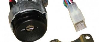
The part of the lock hidden under the lining has the shape of a cylinder with a protrusion on the side, which is a lock for the anti-theft system. At the end of this housing there are terminals to which the wires are connected. There are six of these pins in total, and each of them provides power to certain devices.
Inside the case there is a lock secret and a contact group. The secret makes it possible to operate the lock only with a key that has a certain shape. This is another anti-theft feature, since only a certain key will allow you to switch positions.
Ignition switch VAZ 2101
- Locking rod
- Switch housing
- Roller
- Contact disc
- Contact sleeve
- Block Wide protrusion of the contact part
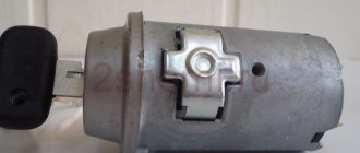
The contact group of the ignition switch 2101 is a special washer with leads for connecting wires. On the inside of it there are nickels of these conclusions, as well as a slider that moves due to the influence of the secretion on it. When moved to certain positions, this slider closes certain nickels with each other, providing electricity to the terminals that are connected to the closed nickels.
Ignition switch contact group
Exactly three switched contacts
One line through which current is supplied, and only one ignition circuit - this solution is typical for all VAZ cars, if we talk about the “2110”, “2170” and later families. Even in Grants, produced since 2012, the additional ignition circuit did not appear. In general, with the transition to the “Ten” family, three “significant” terminals of the lock remained:
- Contact "30";
- Terminal “15” (can be designated as “15/1”);
- Terminal "50".
The ignition switch circuit looks trivial, even if we talk about the Lada 2110.
The Tens connector has 8 terminals. And in Priora, as well as in Grant and Kalina, this number is reduced to three (Fig. 2).
Of the 8 terminals available in the VAZ-2110 connector, the 7th and 8th simply duplicate each other. Two more are connected to the button, and another pair of terminals are connected to the lamp.
The lock connector of all VAZ models, starting from “2170”, is equipped with only three contact terminals. And the additional connector, which is equipped with a pair of terminals, is connected to the immobilizer in these cars.
The “3” mark has disappeared from the “Tens” lock cylinder. And until now, VAZ produces just such locks, where the key can be installed in one of the following positions:
- "Turned off";
- "Ignition";
- "Start".
The presence of the “Parking” mode, as you can see, is not provided here.
Occurring faults
The design of the lock is quite simple and reliable, but the lock may well break. There are only two malfunctions that can happen to this element: mechanical and electrical.
A mechanical failure includes a problem with the secretion. Due to debris that gets inside the secretion and moisture, corrosion is formed, which prevents the movement of moving elements inside the secretion. As a result, the lock begins to jam when you turn the key, jams, or stops rotating altogether. This problem can be eliminated by pouring WD-40 or at least brake fluid inside. However, if it is possible to restore the functionality of the secret in this way, it will not be for long. The secret itself is not repairable, and in the event of such a malfunction, the VAZ-2101 ignition switch will eventually need to be replaced.
An electrical fault is the burning of the nickels of the contact group. Because of this, there will be no or insufficient contact between the runner and the nickel. Electrical appliances on the car will not work, and there may be no power supply to the starter. If the burning was minor, then you can try to restore the functionality of the lock by cleaning the nickels with a diamond file, followed by wiping with alcohol or gasoline. But if the nickels are badly burnt, then you will need to either change the contact group or the lock assembly.
An interesting article about biofuel produced from ordinary sawdust, read more here.
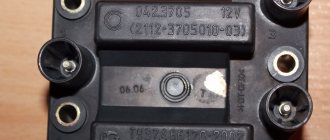
piston markings
The bottoms of different models used on VAZ engines are shown in the figure. The pistons of the VAZ 21213 and VAZ 21230 are distinguished by their markings.
The marking is applied to the surface next to the piston pin hole.
The numbers “213” are printed on the piston of the VAZ 21213, and “23” on the VAZ 2123 model.
Models VAZ 21080, VAZ 21083, VAZ 21100 have the corresponding markings - “08”, “083”, “10”.
The piston 2108 has a diameter of 76mm, models 21083 and 2110 - 82mm.
The pistons of the VAZ 2112 and VAZ 21124 are marked accordingly - “12” and “24” and differ in the depth of recess for the valve.
Models 21126 and 11194 differ in diameter.
Removing and installing the lock
Removing this element from the car is quite simple and all you need is a Phillips screwdriver and a thin flat-head screwdriver or an awl. Before starting work, be sure to disconnect the negative terminal from the battery.
To get to the fastening of this element, you will first need to unscrew the bolts securing the lower facing panel of the steering column, and then remove it.
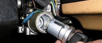
Removing the ignition switch
Afterwards, you need to unscrew the two bolts securing the lock, which hold it in its seat. In the same seat there is a small technological hole. By inserting a thin screwdriver into this hole, you need to press the latch that holds the lock, and then push it out of its seat.
Only then disconnect all the wires. On some models, the wiring going to the lock is collected in a chip that is put on the contacts of the lock. This feature will greatly facilitate the installation of a new element, since such a VAZ-2101 ignition switch does not require a wiring diagram.
How to remove the lock
| Remove the two screws securing the ignition switch (bottom view). | Insert the key into the ignition switch, turn it to position “0” (turning off the anti-theft device), press the lock with a screwdriver through the hole in the bracket and... |
| ...remove the switch from the bracket and the key from the switch. | Label (or remember the connection order) the wires and terminals of the ignition switch. Disconnect the wires from the switch. |
But there are also versions of the car in which the wiring is directly connected to the contacts, and when installing a new element with this type of wiring connection on a VAZ-2101, an ignition switch circuit will be required.
If the lock assembly is replaced, then you can connect the wiring to the new one, install it in place, secure it and cover it with a decorative panel.
If only the contact group is changed, then the removed lock is disassembled. The contact group is fixed using a locking ring, which must be pryed off with an awl or screwdriver and removed. After this you can remove the group. A new one is installed in its place and secured with the same retaining ring. After this, everything is put in place and the VAZ-2101 ignition switch is connected.
Replacement instructions
To do everything right, follow these steps:
First of all, don’t forget to remove the terminals from the battery!
De-energize the car's electrical circuit; to do this, disconnect the battery, so you can prevent a possible short circuit in the wiring during operation. Place the key in the 3Z and turn it 90 degrees. In this position, the system shaft will automatically lock and will not interfere with the removal of the mechanism. To remove the plastic trim from the steering column, you need to unscrew the five fixing screws connecting the upper and lower parts. Both parts of the cover must be removed; do this carefully so as not to damage the casing. Then you need to unscrew two more bolts - with their help the ZZ itself is fixed. These screws are located on different sides of the switch. After these steps, you need to disconnect the cables from the contact group of the node. Use an awl to remove the fastener by reaching into the flat hole with the tool and pressing the latch. At this point, using a flat-tip screwdriver, pry up the assembly and remove it from the bracket. When all the screws are removed and the fasteners are bent, the mechanism can be dismantled without any problems. In the event that you only need to replace the group itself, using the same flat-tip screwdriver you will need to move the ring away - and the element can be removed without any problems. When installing a new contact group, you need to install a pass on the secret part, this way you can make a small engagement. Then the entire structure must be clamped with a spring ring. To install a new switch, first insert the key into it and turn it to position 0. Then tighten the fastener and simultaneously install the switch into the bracket. After this, you need to connect the wires of the replaced ZZ in accordance with the diagram below
The diagram is very important, because if the connection of the contacts is broken, it can lead to a short circuit in the wiring in the network. Accordingly, electrical appliances and devices may eventually fail. Finally, you need to install both parts of the plastic cover and secure them with screws.
Sorry, there are no surveys available at this time.
Connection
Now about the connection. If the wires are assembled into a chip, then there will be no difficulties - we install the chip correctly on the contacts and that’s it.
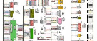
If each wire is connected separately, then you need to follow the diagram:
- To pin 50 – red wire (responsible for the operation of the starter);
- To pin 15 – blue with a black stripe (ignition, interior heating and other devices);
- Pin 30 – pink wire;
- Pin 30/1 – brown wire;
- INT – black wire (dimensions and headlights);
After connecting the wiring, everything is assembled, the terminal is connected to the battery and the functionality is checked. First you need to check whether all electrical appliances powered by the lock are working. Then check the functionality of the starter.
If something does not work, you need to remove the lock and once again check that the wiring is connected correctly, since this alone determines the operation of the devices when you turn the key.
Contactless (electronic) ignition of VAZ 2101. Scheme. Installation procedure
Since more and more owners of VAZ 2101 and “classics” are replacing the old ignition system with a contactless (electronic) one, it would not be a bad idea to talk about it.
Scheme of the VAZ contactless ignition system
Explanation of the scheme:
- Non-contact sensor.
- Ignition distributor sensor.
- Spark plug.
- Switch.
- Ignition coil.
- Mounting block.
- Ignition relay.
- Ignition switch.
The following equipment will be required:
- Switch. Recommended models: K563.3734, K562.3734. The device includes 2 parts: the main unit and an additional one. Additional - serves as a reserve and can take over the tasks of the main unit or Hall sensor in the event of component failure.
- Candles (it is better to use A17 DVR or any similar option).
- Ignition coil marking 27.3705 (magnetic conductor must be open).
- Ignition distribution sensor (marking distributor 38.3706).
- Wire harness.
- High-voltage silicone wires (recommended manufacturers - TESLA or CEZAR).
It is worth noting! If the wires and spark plugs in the system are good, then replacing them is not necessary.
You will need a set of tools:
- keys for spark plugs, 8, 10, 12, 13 millimeters;
- probe 0.7-0.8 millimeters;
- drilling equipment;
- strobe
Ignition installation steps:
- Replace the original spark plugs with a new one (the gap should be set to 0.7-0.8 millimeters).
- Install the switch. The optimal location of the VAZ 2101 is the inner side wall of the compartment. For installation, you will need to drill 2 holes and screw the device to the splash guard with the emergency switch facing up. It is necessary that the switch radiator has a large contact area with the surface of the body (this will increase thermal output). The switch can also be fixed with self-tapping screws.
- Remove the distributor cap and begin turning the crankshaft until the slider turns toward the first cylinder on the distributor. It is worth paying attention that the mark on the crankshaft pulley and the middle mark on the gas distribution system cover must match. Using the key “13” you need to unscrew the distributor and remove it. Take a new distributor and remove the cap from it. Then, turning the rod, scroll it until the slider turns in the direction of the 1st cylinder (as it was on the original distributor). Install a new distributor and tighten the nut to thirteen. Next, scrolling it in a circle, relative to its axis, position it so that the central point of the Hall device coincides with the edge of the beginning of the window cutout in the screen. Then, you can tighten the nut securing the distributor to the end.
- Replace the ignition coil. The procedure includes the following steps: unscrew the old coil (in this case, the conductors do not need to be removed from its terminals);
- replace with a new part;
- the wiring harness is connected using connectors to the switch and ignition distribution device;
- the black conductor is connected to ground (the terminal must have a tight connection to the car body);
- the red conductor is connected to terminal “K” on a new copy of the part;
- the brown wire from the tachometer (disconnected from the previous part) is also connected to “K”;
- The blue wire and the black-blue wire (disconnected from the previous part) are connected to terminal “B”. It must be taken into account that components “K” and “B” cannot always be placed symmetrically.