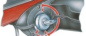
On Kalina cars, the generator is three-phase and produces alternating current. There is no need to go into too much theory; an ordinary motorist only needs to know how to independently diagnose and repair the installation. This means installing the generator and voltage regulator directly. The fact is that at the output of the power windings the voltage jumps in the range of 10-30 V, and to power the entire on-board network you need 12 V. The first step is to rectify the voltage and then stabilize it.
Design of a car generator
Any generator, with the exception of direct current models, creates multiphase alternating current - three or four phases, depending on the power.
Why such a complication if the on-board network uses only direct current anyway? The fact is that a multiphase alternating current generator has higher efficiency, and most importantly, the current is removed not by brushes from the rotating rotor, but from the stationary stator windings. Accordingly, there are no problems with burnout of the collector (the current in it is much less than what the generator produces), and the collector itself is simpler - two rings, and not a set of insulated lamellas. To convert polyphase alternating current into direct current, a diode bridge is used. At a minimum, it contains several powerful diodes with twice the number of phases - they are engaged in rectifying the current. Some generators also have additional diodes that provide power to the relay regulator.
The relay-regulator itself is no longer a relay: instead of an electromechanical device, electronic circuits are used to control generators, but the name “relay-regulator” has already firmly established itself behind it. They operate in the same way - by changing the current in the rotor winding (and the magnetic field in the core), they increase or decrease the voltage at the generator output so as to keep it within specified limits from 13.7 V (old low-power generators) to 14.5 V (modern generators designed for high power consumption of the on-board network and accelerated battery charging). Modern generators are no longer independent units, but are integrated with on-board controllers: the ECU controls the voltage, raising it after the engine starts to speed up battery charging, and then lowering it to normal.
The relay-regulator is powered from an external network (Zhiguli, most foreign cars) and from the generator itself through additional bridge diodes (front-wheel drive VAZs). The second circuit is considered less reliable, but has a distinctive ability to self-excite due to the residual magnetization of the rotor - the generator, spun up to high speeds, produces enough current for the relay-regulator to operate and bring it to operating mode.
The generator must always be in good working order
Any modern car is equipped with electrical equipment that is absolutely necessary for the vehicle:
- without a starter it is impossible to start the engine;
- a car cannot be driven without lighting at night;
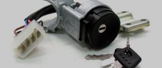
- The heater motor creates heat in the cabin;
- The wiper motor clears the windshield of rain and snow;
- FM radio makes it possible for the driver not to get bored on the road.
But all these devices cannot work without electricity, so the car must have a power source.
The current from which all consumers in the car are powered is produced by the generator, and the performance of the entire electrical circuit of the vehicle depends on its condition.
Therefore, the generator must always be in good working order, and if any breakdowns occur with it, they must be eliminated in a short time.
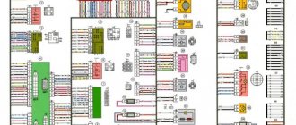
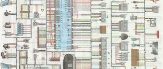
Album of schemes for "VAZ 1118"
The Lada Kalina technical manual has such an album. The general scheme includes 59 components, among which you can find:
- sources and consumers;
- protective and control elements;
- ECU;
- sensors
A separate printed block displays the electrical circuit for connecting the electronic motor control module with other system components. We are talking about spark plugs, injectors, sensors, and the ignition unit of the Lada Kalina car.
There is also a separate electrical diagram that highlights the front and rear cable harnesses. A detailed display of all connections of the electrical components of the front panel in the cabin is provided. In addition, the diagram contains clear connections for the wiring harnesses of the door panels and the interior ventilation unit.
In order for the cable connections to ensure reliable contact, they are connected to special blocks with terminals. All terminals are compatible with cable harnesses, the wires of which have their own characteristic sheath color. Each electrical diagram in the album is designed in such a way that the color shade of the sheath of a particular cable actually matches the color shown in the documentation.
Numbers are written next to the drawn lines, allowing you to use the symbols to determine the connector to which a particular wire fits. For example, the marking on the “9/14” diagram “tells” us that this cable is connected to the 9th block via connector No. 14.
no charging! no excitation to the generator itself
You check with a control. ) I explain the principle in my fingers. A plus appears on the control panel. The second end from the control went to the generator. While it is standing there is a minus coming from the generator through the brushes and windings. The control lights up. As soon as current flows from the generator, a plus appears on this contact, and the pluses at the two ends of the control are equal to zero, the control goes out. Now the next thing. In the panels, depending on the modification, the control unit is not a lamp, but an LED (by the way, most often). When checking with the control, the control lamp (LED) lights up successfully, but the control simply does not react, well, it has too much power for this. I repeat, a working generator 2112 (this is the one on the injectors) will work without this wire, it just won’t charge right away, and when you accelerate, you raise the speed. It will self-excite perfectly through the small diodes of the bridge.
Vladimir Generalov Yes, it always lights up even when you disconnect the 2 swamp in the mounting block from the generator, as Andrey Potapenko said
Source
Checking ventilation and stove Lada Kalina
Car owners claim that Kalina’s heater heats much better than previous VAZ models. It sometimes breaks down and requires repair. Do a full system diagnostic to ensure it's working properly.
- We start the car engine.
- Turn the left handle counterclockwise and place it in the blue zone.
- We place the fan speed switch in each of the 4 positions one by one. If the fan does not rotate in one of the positions, then check the power supply circuit of the device.
- Turn the speed controller to maximum.
- Using the right handle (damper control) we check the redirection of air flows. If we notice that there is no change, then the damper drive needs to be repaired.
- Warm up the engine to 90°C. Turn the left handle to the extreme position of the red zone.
- The air that comes out of the panels should blow warm air.
- Return the left stick to the blue zone. Cold air will come out of the nozzles again.
- If the temperature of the air flow does not change due to a change in the position of the regulator, then the control of the central damper drive is faulty.
The car owner may not immediately understand that the Kalina interior heater, the circuit of which is simple, is damaged. You constantly add antifreeze in small quantities, and the carpet in the cabin is dry and there is no smell of antifreeze. A stove leak does not appear immediately, and the main thing is that the liquid can evaporate. The radiator on Kalina does not have pipes leading into the cabin that could leak.
No excitation of the VAZ Kalina generator
- Registration
- Entrance
- To the beginning of the forum
- Forum Rules
- Old design
- FAQ
- Search
- Users
I recently became the owner of an alarm system with auto start and discovered the following thing: when you start the car with a cold engine, the generator is excited only after re-engineering.
Is this glitch observed only in autorun mode or does it (or did it?) occur?
No, the belt is fine. I checked that it was tight. They say that the tenth family has a disease. If you don’t believe me, let him start it when it’s cold (the main thing is not to press the gas) and look at the voltage on the on-board computer.
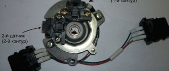
1) Put the key in the 1st position. There is no need to start the engine. 2) Set the multimeter to DC voltage measurement mode. You remove the excitation chip from the generator, measure the voltage between the chip and ground. It should be about 6 Volts (if there is a resistor in the device) and about 12 Volts if there is no resistor in the device:
3) Switch the multimeter to DC measurement mode (10 or 20 A “unfused”, depending on the type of multimeter). You stick one end into the chip, and with the other you touch the output of the regulator on the generator (from which you removed the chip):
The multimeter should show about 140 mA if there is a resistor in the device and about 240 mA if there is no resistor:
If everything went well in steps 2 and 3, look at the small bridge diodes, regulator and brushes.
4) If according to step 3 there is no required current, touch the ground (with the probe that was used to hold the generator). Should be about 150 mA:
If there is no current according to step 4, look at the light bulb in the dash and the wiring.
Source
Replacing generator brushes for Lada Kalina sedan (VAZ Kalina)
If the voltage regulator unit, capacitor and not a tight fit of the brushes are faulty, or if they are worn out, the vehicle's supply voltage deviates from the norm. In this case, it is necessary to check the above listed elements and, if necessary, replace them. In this article we will talk in more detail about diagnosing and replacing generator elements in a Lada Kalina car.
To remove the Lada Kalina voltage regulator you will need the following tool:
flat-blade screwdriver, 8mm and 10mm open-end wrenches and 7mm, 8mm and 24mm socket wrenches, hammer, soldering iron, universal meter (with DC voltmeter and megger)
Checking the functionality of the voltage regulator on the Lada Kalina generator
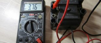
1. Move aside the rubber insulating cover of the positive terminal from the generator.2. Start the engine and allow the engine to warm up so that the vehicle operates normally at idle speed.3. Measure the voltage between the positive terminal and the body (negative terminal). The voltage should be 14.5-15.1 volts.
If there is a deviation from the specified range, the voltage regulator must be replaced. See also checking the Lada Kalina generator regulator in the section “Replacing the voltage regulator”
Checking the functionality of the Lada Kalina generator capacitor
The capacitor is usually checked with a specialized meggometer, since not all universal devices have a measurement of up to 10 MoM. The device is set precisely in the range of 1-10 MΩ. Before connecting to the capacitor, the device shows infinity. If connected to a working capacitor, it begins to charge and an electric charge accumulates on its plates - current flows and, accordingly, the resistance on the device drops. After charging it (saturating the capacitor plates), the resistance again becomes infinite.
Replacing the voltage regulator Lada Kalina
carried out as follows
1. Disconnect the negative cable from the battery.2. Disconnect the excitation block from the generator.
3. Disconnect the positive terminal from the battery by unscrewing the nut.
4. Remove the factory seal from one of the screws holding the plastic casing and remove the screws. Remove the protective plastic cover.5. Remove the two screws securing the regulator and remove the voltage regulator.
6. Check the ease of movement of the brushes. They must protrude at least 5 mm from the voltage regulator housing.7. You can check the voltage regulator by connecting a 12 V lamp to its outputs and applying a voltage in the range of up to 12 volts to its inputs, while the lamp should light and the voltage is more than 12 V to 16 V.
If the voltage is too high, the lamp should go out. If this algorithm does not work, then the regulator must be replaced. Installation of the regulator is done in the reverse order.
Replacing the rectifier unit with a capacitor Lada Kalina
1. Using a soldering iron, unsolder the six leads and remove the 3 bolts.
2. Remove the rectifier unit from the generator. Installation of the rectifier unit is carried out in the reverse order
Checking diodes on the rectifier block Lada Kalina
1. Dodas are checked with a universal device. (6 diodes in total) Connect the black “negative” probe to the negative plate, and the positive “red” probe alternately to the three contact terminals of the diodes. The resistance should be 580-620 Ohms.
Attach the red “positive” probe to the negative plate, and the negative “black” probe alternately to the three contact terminals of the diodes. The resistance should be 580-620 Ohms.
Checking the windings of the Lada Kalina generator
1. Check the generator windings with a device. All windings should have approximately equal resistance, without significant deviations. Deviations indicate a break or short circuit.
Any electrical equipment fails sooner or later. Thus, the most common generator malfunction on the Lada Kalina remains the regulator relay. Replacing this element is not difficult, but requires certain knowledge and skills.
Video on replacing the voltage regulator relay on a Lada Kalina:
This video story tells about replacing the generator regulator relay on a Lada Kalina, the nuances of installation and configuration.
Ignition system diagram Lada Kalina Lux
1 – oil pressure warning lamp sensor;
2 – coolant temperature indicator sensor; 3 – additional fuse block; 4 – fuses for the electric fan of the engine cooling system; 5 – electric fuel pump relay; 6 – relay for the electric fan of the engine cooling system; 7 – ignition relay; 8 – relay 2 of the electric fan of the engine cooling system; 9 – relay 3 of the electric fan of the engine cooling system; 10 – electric fan of the engine cooling system; 11 – throttle position sensor; 12 – idle speed regulator; 13 – coolant temperature sensor; 14 – diagnostic block; 15 – ignition system harness block to the instrument panel harness block; 16 – solenoid valve for purge of the adsorber; 17 – speed sensor; 18 – ignition system harness block to instrument panel harness block 2; 19 – mass air flow sensor; 20 – crankshaft position sensor; 21 – oxygen sensor; 22 – controller; 23 – rough road sensor; 24 – diagnostic oxygen sensor; 25 – ignition coil harness block to the ignition system harness block; 26 – ignition coils: 27 – ignition system harness block to the ignition coil harness block; 28 – spark plugs; 29 – nozzles; 30 – resistor; 31 – air conditioning system pressure sensor; 32 – blocks of the ignition system harness and injector wiring harness; 33 – phase sensor; 34 – knock sensor. Ignition system wiring harness -11184-3724026-10. Ignition coil wiring harness -1118-3724148-00. Injector wiring harness -11184-3724036. A – to the “plus” terminal of the battery.
On Kalina cars, the generator is three-phase and produces alternating current. There is no need to go into too much theory; an ordinary motorist only needs to know how to independently diagnose and repair the installation. This means installing the generator and voltage regulator directly. The fact is that at the output of the power windings the voltage jumps in the range of 10-30 V, and to power the entire on-board network you need 12 V. The first step is to rectify the voltage and then stabilize it.
generator viburnum
Post by sea » January 28, 2014, 12:00
Post by puh » Jan 28, 2014 01:46 pm
Post by Parodist » Jan 29, 2014, 02:52 p.m.
Post by Sasha-Irpen » 30 Jan 2014, 06:38
Post by puh » 30 Jan 2014, 08:53
Post by Sasha-Irpen » 30 Jan 2014, 10:23
Honestly, it’s a pity to waste time explaining basic truths, but since I seem to have chewed everything out in great detail (especially since such information is not secret and is on the Internet), I’ll explain it again, but more slowly. (For those in the tank).
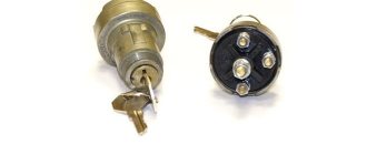
There are generally accepted digital symbols in electrical circuits. 1). The direct “+” of the battery is usually designated as “30” and, most often, purple (red) wires are used for this bus. For example, on the generator, near the power bolt you can see the designation “30”. If you have noticed, when the ignition is turned off, on some sensors with an oscillator with an input voltage of 1 mOhm, you can see a voltage of several volts. BUT, can we say that they have a “30” tire? 2). The voltage appearing after the ignition switch is usually designated “15”. (Options 15/1, 15/2 are possible). On a VAZ this is a wire, usually blue (possibly with a black stripe). On the contact group of the ignition switch you can see both 30 and 15 and even 50. (“50” is the starter retractor). In my understanding, bus “15” is a voltage of approx. 12 volts, which appears after turning on the ignition and is capable of powering a load of several amperes. 3). On the decimal generator, near the 6.3 mm plug, it says D+, or “61”. So 61 is a bus for excitation of the generator; on a VAZ it is connected with a brown wire with a white stripe and has nothing in common with bus 15, since it has its own name - 61. If, with the ignition on, measure the voltage on this plug, its value will be from 1 to 3 volts. This is another confirmation that this is not a “15” tire. If you try to connect a load to this wire (even a light bulb from the dimensions), then this light bulb will not light up, and the maximum that can be achieved is that the light bulb on the instrument panel with the battery drawn will light up. 4). I hope that there is no need to talk about tires “31”, “49”, “56”, “58”, etc.? Dear, it seems that you have small gaps in your knowledge, so it’s better to learn the materiel.
On Kalina cars, the generator is three-phase and produces alternating current. There is no need to go into too much theory; an ordinary motorist only needs to know how to independently diagnose and repair the installation. This means installing the generator and voltage regulator directly. The fact is that at the output of the power windings the voltage jumps in the range of 10-30 V, and to power the entire on-board network you need 12 V. The first step is to rectify the voltage and then stabilize it.
About the principle of operation of a car generator
The operation of the Lada Kalina generator unit is based on the following principle: an alternating current is induced in the stator winding, which is subsequently transformed into direct current through a rectifier module located on the body of the unit. The generator cover is also equipped with an electronic voltage regulator and a brush holder. The rotor of the device receives torque from the crankshaft pulley. The transmission link is a poly V-belt.
The basic characteristics of the generator set include the following parameters:
- maximum generated current – 85-90 Amperes;
- operating range of on-board voltage – 14.4-15.1 Volts;
- rotation ratio of the motor and rotor – 1:2.4;
- right-hand direction of rotation.
The housing of the unit is held together by pins that tighten the stator with the covers. The mounting sockets of the indicated covers contain bearings, which ensure the ability of the rotor to rotate. The rear bearing is installed inside the cover with a minimum gap. The front element is equipped with the ability to slide along the surface of the rotor shaft. It is fixed inside the front cover with a slight interference fit, and a pressure plate covers it from the outside. The back of the device is protected by a plastic casing.
Let's move on to the switching diagram of the generator with the on-board network. The connection diagram is very simple. After turning on the ignition, power begins to flow to the voltage regulator through the battery discharge lamp circuit. When the motor starts, the excitation winding is supplied with supply voltage from three diodes mounted in the rectifier unit.
Using the indicated signal lamp, the generator unit can be checked. If the device is working properly, the lamp lights up when the ignition is on. It goes out when the engine starts. When this phenomenon is not observed and the lamp continues to shine, the generator set should be diagnosed for the presence of malfunctions. In some cases, replacement is required, and many are interested in how to remove the generator?
GeneratorLada Kalina
Generators 9402.3701-06 or 5132.3771 are installed on cars. The generator is a synchronous alternating current electric machine with electromagnetic excitation and a built-in rectifier using silicon diodes. The generator rotor is driven by a poly-V belt from the engine crankshaft.
| Generator Specifications | |
| Maximum output current (at 14 V and 6000 min-1), A | 85 or 90 |
| Voltage, V | 14,4-15,1 |
| Engine-generator gear ratio | 1:2,4 |
| Direction of rotation (drive side) | Right |
The stator and generator covers are secured with four bolts. The rotor shaft rotates in bearings installed in the covers. The lubricant placed in the bearings at the factory is designed to last the entire service life of the generator. The rear bearing is pressed onto the rotor shaft and installed in the rear cover with a small gap. The front bearing is installed in the front cover of the generator with a slight interference fit and closed with a pressure plate; the bearing has a sliding fit on the rotor shaft. The back of the generator is covered with a plastic casing. The generator stator contains a three-phase winding. The ends of the phase windings are connected to a rectifier bridge consisting of six (or eight) silicon diodes (valves): “positive” and “negative”. The valves are pressed into two horseshoe-shaped aluminum holder plates in accordance with the polarity (“positive” and “negative” - on different plates). The plates are combined into a rectifier unit mounted on the back cover of the generator (under a plastic casing). The excitation winding is located on the generator rotor, its leads are soldered to two copper slip rings on the rotor shaft. Power is supplied to the field winding through two brushes. The brush holder is structurally combined with the voltage regulator and is mounted on the back cover of the generator (under a plastic casing). The voltage regulator is non-separable; if it fails, the brush holder with the regulator assembly is replaced. To protect the on-board network from power surges during operation of the ignition system and reduce interference with radio reception, a capacitor is connected between the terminals of the “positive” and “negative” valves (between the “+” and “ground” of the generator). When the ignition is turned on, voltage is supplied to the generator excitation winding (terminals “L” or “D+” of the generator and “+” of the regulator) through the signaling device and resistors in the instrument cluster (the signaling indicator is lit). After starting the engine, the excitation winding is powered by the diodes of the rectifier unit (the alarm goes off). If the indicator lights up after starting the engine, this indicates a malfunction of the generator or its circuits.
The “minus” of the battery should always be connected to the “ground” of the car, and the “plus” to the “B+” terminal of the generator. Switching back on will lead to breakdown of the generator valves. It is not recommended to disconnect the battery while the engine is running. The resulting voltage surges in the on-board network can damage the electronic components of the circuit. The generator valves (and other devices in the vehicle’s on-board network when the generator is connected) should be checked at a voltage no higher than 14 V; a higher voltage (for example, when checking with a megger) can cause damage to the valves. If it is necessary to check the insulation of windings with high voltage, the generator should be removed, and the winding terminals should be disconnected from the rectifier unit and voltage regulator.
Generator mounting parts: 1 - upper bolt; 2 - nut; 3 — generator bracket; 4 - nut; 5 — bushings; 6 - bottom bolt.
The generator is mounted on a bracket fixed to the engine. The generator is attached to the bracket with two bolts and nuts. The head of the upper bolt is kept from turning by two protrusions on the bracket. The lower bolt nut is installed in the hexagonal recess of the bracket. A spacer sleeve is installed in the lower left hole of the bracket for the generator mounting bolt.
content .. 220 221 222 223 224 225 226 227 228 229 ..
Checking the rectifier unit (diode bridge)
To perform this diagnostic, it is necessary to remove the diode bridge from the Kalina generator; this was described in more detail in previous articles in this section.
Then we connect the tester with the black wire to the negative plate of the block, and the red one in turn to the three contact terminals of the diodes. This way we check all the rectifiers in the block. The values on the device should be in the range from 400 to 800 Ohms. Personally, on my Kalina, during this test, all diodes showed a resistance within 535 Ohms. But the repair instructions from the Third Rome publishing house talk about numbers of 580-620 Ohms. I will say right away that when I rang two serviceable generators, the values specified in the manual were not achieved, although there were no problems with charging, so I personally doubt the accuracy of the data in this instruction.
Then we carry out the same operation, only swapping the contact wires of the multimeter. In this case, the device, with working diodes, will show infinity, that is, its readings will not change:
Electrical equipment Lada Kalina
If the voltage regulator unit, capacitor and not a tight fit of the brushes are faulty, or if they are worn out, the vehicle's supply voltage deviates from the norm. In this case, it is necessary to check the above listed elements and, if necessary, replace them. In this article we will talk in more detail about diagnosing and replacing generator elements in a Lada Kalina car.
To remove the Lada Kalina voltage regulator you will need the following tool:
flat-blade screwdriver, 8mm and 10mm open-end wrenches and 7mm, 8mm and 24mm socket wrenches, hammer, soldering iron, universal meter (with DC voltmeter and megger)
Checking the functionality of the voltage regulator on the Lada Kalina generator
1. Move aside the rubber insulating boot of the positive terminal from the generator. 2. Start the engine and allow the engine to warm up so that the vehicle operates normally at idle speed. 3. Measure the voltage between the positive terminal and the body (negative terminal). The voltage should be 14.5-15.1 volts.
If there is a deviation from the specified range, the voltage regulator must be replaced. See also checking the Lada Kalina generator regulator in the section “Replacing the voltage regulator”
Checking the functionality of the Lada Kalina generator capacitor
The capacitor is usually checked with a specialized meggometer, since not all universal devices have a measurement of up to 10 MoM. The device is set precisely in the range of 1-10 MΩ. Before connecting to the capacitor, the device shows infinity. If connected to a working capacitor, it begins to charge and an electric charge accumulates on its plates - current flows and, accordingly, the resistance on the device drops. After charging it (saturating the capacitor plates), the resistance again becomes infinite.
Replacing the voltage regulator Lada Kalina
carried out as follows
1. Disconnect the negative cable from the battery. 2. Disconnect the excitation block from the generator.
3. Disconnect the positive terminal from the battery by unscrewing the nut.
4. Remove the factory seal from one of the screws holding the plastic casing and remove the screws. Remove the protective plastic cover. 5. Remove the two screws securing the regulator and remove the voltage regulator.
6. Check the ease of movement of the brushes. They must protrude at least 5 mm from the voltage regulator housing. 7. You can check the voltage regulator by connecting a 12 V lamp to its outputs and applying a voltage in the range of up to 12 volts to its inputs, while the lamp should light and the voltage is more than 12 V to 16 V.
If the voltage is too high, the lamp should go out. If this algorithm does not work, then the regulator must be replaced. Installation of the regulator is done in the reverse order.
Replacing the rectifier unit with a capacitor Lada Kalina
1. Using a soldering iron, unsolder the six leads and remove the 3 bolts.
2. Remove the rectifier unit from the generator. Installation of the rectifier unit is carried out in the reverse order
Checking diodes on the rectifier block Lada Kalina
1. Dodas are checked with a universal device. (6 diodes in total) Attach the black “negative” probe to the negative plate, and the positive “red” probe alternately to the three contact terminals of the diodes. The resistance should be 580-620 Ohms.
Attach the red “positive” probe to the negative plate, and the negative “black” probe alternately to the three contact terminals of the diodes. The resistance should be 580-620 Ohms.
Checking the windings of the Lada Kalina generator
1. Check the generator windings with a device. All windings should have approximately equal resistance, without significant deviations. Deviations indicate a break or short circuit.
Symptoms of loss of battery charging on a Priora
The very first thing that many people pay attention to is that the battery charging light on the dashboard came on. If you have a multimeter at hand, you can measure the output charging current by connecting the contacts to the “+” and “-” terminals, respectively
If even without a load the device readings are less than 13 Volts, this indicates that there are certain problems with charging.
Of course, it is possible (although it is highly not recommended) to remove the “-” terminal from the battery while the engine is running, thereby checking the functionality of the generator. If the engine stalls, this will indicate that there is actually no charging, and accordingly, the generator is faulty.
Also, the charging lamp may glow at half-glow, which also indicates insufficient charging current. If one of the symptoms listed above occurs, it is necessary to diagnose the generator and its parts. If necessary, replace them with new ones. If you have anything to add to this article, you can comment below.
If the battery discharge indicator lights up in the instrument cluster, it means that current is not flowing from the generator to the on-board network and the battery's energy reserves are being consumed. Once the battery is discharged to its minimum value, the engine management system will stop working and the engine will stall. Let's look at the main reasons why charging from the generator to the battery does not occur.
A car has two power sources: a battery (battery) and a generator. The battery is used when starting the engine (to power the starter), as well as for other consumers when the engine is not running. After starting the engine, the main source of current is the generator. It supplies current to all consumers, including the ignition system, and charges the battery.
How long can you drive without a battery-powered generator?
To save battery energy, turn off unnecessary electricity consumers: audio system, heated seats, etc. Also try not to stop and start the engine unless necessary. Under normal conditions, a fully charged battery in the absence of charging current lasts for approximately one hour of driving. See experiment with Lada Largus.
How to find the reason why the generator does not charge the battery
:
1. Check to see if the accessory drive belt (or alternator belt) is broken. If the belt is intact, check its tension.
2. If the belt tension is normal, but the warning light is still on, check that the wiring harness block and the positive wire terminal are securely connected to the generator
Please note that wires may be broken or broken within the insulation
3. Check the reliability of the wire connections to the battery terminals.
4. Check the integrity of the generator fuse in the engine compartment mounting block. Replace the blown fuse if necessary.
If, after all the measures taken, the charging lamp continues to light up while the engine is running, then most likely the generator is faulty (for example, the voltage regulator is faulty). We told you how to check the generator earlier.
The battery and generator are the two sources of electricity. The battery is used to start the engine and to recharge the vehicle's systems if the generator cannot cope with the load. The role of the generator is to provide power to current consumers in the on-board network when the engine is running and recharge the battery. It is this last function that will interest us. During operation, it is not uncommon for the battery to not charge during a trip or to receive insufficient charge. Let's look at the reasons for this.
Why does the generator heat up on viburnum?
Welcome to ChipTuner Forum.
Theme Options
On the original Kalinovsky generator, a couple of diodes burned out and the stator insulator melted. Instead, I installed the entire rear part from a VAZ 2110 (the armature remained the same). Now charging has appeared and there is a problem with it - the generator began to get very hot. Colleagues, tell me what’s wrong?
Prohibited in conferences
— Direct or indirect advertising of sites, products and services. — Direct or indirect insults to other participants. — Search and offers of freebies, cracks, programs, Viagra, sexual partners, exchange of commercial products, etc. — Russian warez is prohibited. — Discussion of the actions of the administrator and moderators. — Profanity in open form. — Scam and maintenance of demagogic flood and flame in technical sections.* — Creation of topics like “HELP. » with current and minor questions inside. - Write in CAPITAL LETTERS LIKE THIS
— Use red
and
green
color. These colors are used by the administrator and moderators to write messages inside user posts.
Messages: 1420 Registered: April 7, 2011, 00:00 Experience: since April 28, 2010 Car: VAZ-2113 Awards: 1
| 5 455 |
| Reputation: +9 |
Thanked: 1 time Thanked: 18 times
Problem with generator, hums and stinks
Post by DMMC » 07 Jan 2015, 18:52
It all started with the battery charge light, which did not light up when it was cold. As soon as everything warmed up, it caught fire. By the method of elimination, it was revealed that the lamp itself was working. An insulation breakdown was discovered on the diode bridge, or more precisely on the wiring that goes to the voltage regulator (I did it by accident). I spat and decided to change the diode bridge yesterday. Bridge from Niva 2123, 2 additional ones go to it. output from the regulator. At the beginning, one pin was attached to the wrong place, one should go to + and the other to -. It turned out that both were at minus, charging did not occur.
I redid it today. Charging appeared, BUT! The generator began to hum and smell like some kind of burnt plastic, a very similar smell. The most interesting thing is that if you pull out the voltage regulator, it doesn’t make noise or smell. I thought it was a problem with the regulator, installed a second one, which was known to be working, nothing changed - a hum and a stench. There is charging, the lamp is still not on.
Tell me what I did there and how much money I got into, it’s scary to drive, God forbid something else breaks out, tomorrow I plan to tow the car to AvtoVAZ, at least I know roughly what to prepare for...
On the Internet I came across an article that described similar symptoms and there was a malfunction of the diode bridge. Where did the noise and stench come from then? Auto VAZ 2113
Most likely the brushes were worn out.
remove the wires from the generator. you take off the black cover with three latches. and then 2 screws with a screwdriver. (or head 8. I don’t remember exactly)
for 8th grade car no problem. for 16th grade There may be access and visibility issues. It may be easier to remove the generator on a 16 valve machine, because To change the relay by touch, you need to do it once.
If replacing the brushes does not help, then feel free to change the generator.
The first time it took me a long time to remove the generator, now I do it in 5 minutes. and I'll put it at 8. but I have an 8 cl car.
Do I have to lift the truck or can I climb on top? I also have 8.
for 8th grade everything is on top. for 8th grade try without removing the genes. Change the brushes in any case, even if they are not worn out. because they are in the same housing with a voltage regulator which also often lies.
if replacing the brushes does not help. then I advise you to replace the gene. I have already twisted their power. no resource. I realized that time and nerves are more valuable than genes.
Kalinovsky Kzate resource 30 thousand km
If you don't twist it with your fingers, it shouldn't fall off.
The fact of the matter is that in both cases the bolts broke off, the nuts remained, but the bolts were torn off.
Tell me how to determine the interturn short? There is an interturn breakdown in the rotor windings. determined by measuring voltage at idle and at high speeds. if there is a breakdown, then the voltage is noticeably less than it should be, and at idle it is even less than just on the battery.
Previously, I didn’t pay attention to whether the generator was heating up on cars. It heats up, and very well. on viburnum it is very hot, normal
Added after 2 minutes which even echoes into the steering wheel from a faulty generator bearing?
It's unlikely that it's from the bearing.
It's unlikely that it's from the bearing.
I removed the generator today and found no bearing runout. Well. We'll keep looking))
How to excite a generator directly prior
- Registration
- Entrance
- To the beginning of the forum
- Forum Rules
- Old design
- FAQ
- Search
- Users
I recently became the owner of an alarm system with auto start and discovered the following thing: when you start the car with a cold engine, the generator is excited only after re-engineering.
Is this glitch observed only in autorun mode or does it (or did it?) occur?
No, the belt is fine. I checked that it was tight. They say that the tenth family has a disease. If you don’t believe me, let him start it when it’s cold (the main thing is not to press the gas) and look at the voltage on the on-board computer.
1) Put the key in the 1st position. There is no need to start the engine. 2) Set the multimeter to DC voltage measurement mode. You remove the excitation chip from the generator, measure the voltage between the chip and ground. It should be about 6 Volts (if there is a resistor in the device) and about 12 Volts if there is no resistor in the device:
3) Switch the multimeter to DC measurement mode (10 or 20 A “unfused”, depending on the type of multimeter). You stick one end into the chip, and with the other you touch the output of the regulator on the generator (from which you removed the chip):
The multimeter should show about 140 mA if there is a resistor in the device and about 240 mA if there is no resistor:
If everything went well in steps 2 and 3, look at the small bridge diodes, regulator and brushes.
4) If according to step 3 there is no required current, touch the ground (with the probe that was used to hold the generator). Should be about 150 mA:
If there is no current according to step 4, look at the light bulb in the dash and the wiring.
Source
Main process
Replacing the generator in the case of Kalina with an 8-valve or 16-valve engine involves performing the following steps:
- First of all, you will need to install the car on the repair site and fix the position of its wheels using wheel chocks. It is also necessary to turn off the engine and disconnect the terminals from the battery to ensure the safety of the work being carried out.
- After this, you need to loosen the belt tensioner roller, which fixes the position of the generator. To do this, you will need to unscrew the fasteners and dismantle them.
- The next step is to disconnect the plug secured by a plastic latch. To remove it, you need to lightly press it and pull it to the side. If everything is done correctly, the plug can be removed without problems.
You will also need to remove the wire terminals located under the protective cap. Therefore, the car owner will first need to dismantle the protective cap by prying it off, and only then remove the terminals.
The next step is to unscrew the nut securing the upper part of the generator. It is considered the most complex process among those listed, and it is better to familiarize yourself with the structure of the car in advance so that no problems arise. To make the nut give way quickly, you can move it with a wrench and then work it with a ratchet handle. Finally, all that remains is to lightly tap the protruding bolt so that it moves, after which you can remove it from the reverse side. Once the top bolt of the generator is removed, you can proceed to the bottom one. The actions are the same - a knob, a ratchet handle, a light knock and dismantling. However, in this case, it is recommended to hold the nut on the reverse side so that it does not turn. Next, you should begin dismantling the rod
This should be done carefully and carefully, since there are bearings and bushings inside. They will need to be held so that they do not fall and get lost.
The final step will be to dismantle the generator, clean the internal space of dirt, rust, possible traces of oil, and install a new unit - a standard generator or its equivalent.
You can check the functionality of the generator with a multimeter by connecting it to the battery terminals. The voltage reading should not be less than 13.4 volts.
The pitfall when replacing a Lada Kalina generator with air conditioning is its changed position, so you will have to approach it from the other side.
Thus, in order not to have to change the generator frequently, it is recommended to regularly inspect the technical condition of the car and, if necessary, repair certain parts, devices, and systems. Undoubtedly, repairs will cost the owner of Kalina somewhat less than buying new spare parts and entire units.
On Kalina cars, the generator is three-phase and produces alternating current. There is no need to go into too much theory; an ordinary motorist only needs to know how to independently diagnose and repair the installation. This means installing the generator and voltage regulator directly. The fact is that at the output of the power windings the voltage jumps in the range of 10-30 V, and to power the entire on-board network you need 12 V. The first step is to rectify the voltage and then stabilize it.
How to remove the generator on the LADA Granta
The “Grants” generator has to be removed for various reasons: for repair, maintenance, modification of the unit. You can do this without the help of others if you know how to remove the generator on the Grant. Depending on the modification of the car (8 or 16 valve engine, presence of air conditioning), the procedure for dismantling the generator has its own characteristics, so it is worth considering each option separately.
How to remove a generator on an 8-valve Grant without air conditioning
The following will be useful for work:
Before removing the generator on a Grant without an air conditioner, you should disconnect the ground from the battery by removing the negative terminal. The procedure is as follows:
- unscrew the 2 rear bolts securing the motor protection;
- unscrew the 4 front motor protection bolts;
- remove the engine protection (mudguard) from the car;
- disconnect the wiring block from the generator;
- remove the protective cap of the nut holding the power wire;
- unscrew the nut and disconnect the generator power cable;
- unscrew the top nut securing the “Grant” generator;
- press out the generator with a mounting spatula and remove the upper mounting bolt;
- unscrew the lower bolt securing the generator;
- move the generator away from the engine with a mounting blade and remove the lower mounting bolt;
- move the generator towards the right mudguard;
- remove the generator belt from the unit pulley;
- pull out the generator;
- Remove the alternator belt from the crankshaft pulley.
To put the LADA “Grant” generator in place, you need to perform the steps in reverse order.
Important: when installing the generator belt, make sure that the pulley grooves and the groove tracks on the belt match
How to change the generator on a 16-valve Grant
The generator mount on the 16-valve Granta variation is distinguished by the presence of a belt tensioning mechanism. Therefore, the procedure for replacing the generator on this model is slightly different. To work, you will need socket wrenches 8, 10 and 13. As when dismantling the generator from the 8-valve Granta, before starting work you need to remove the ground terminal from the battery to eliminate the possibility of a short circuit.
Removing the generator
Lada Kalina
, change the armature contact rings.
Replacing the slip rings of the VAZ Kalina generator. How to remove the generator.
How to remove the generator
for 16th grade Kalina
.If you have any questions, you can ask them in the VKontakte group -…
After this, you need to remove the engine protection by unscrewing the 4 front and two rear bolts securing it to the body parts. The 16-valve “Granta” generator is removed as follows:
- disconnect the block from terminal “D” on the generator;
- remove the rubber cap covering the “B+” terminal of the generator;
- Using a 10mm wrench, unscrew the nut holding the wire tip;
- loosen the tension bar nut using a 13mm wrench;
- by rotating the tensioner adjusting bolt counterclockwise, loosen the tension on the Grant generator belt (a 10mm socket wrench is required);
- move the generator towards the engine and remove the belt from the pulleys;
- Unscrew and remove the adjusting bolt of the belt tension mechanism from the generator mounting bracket;
- remove the tension bar;
- unscrew the lower nut securing the “Grant” generator;
- remove the spacer bushing and remove the lower mounting bolt;
- remove the tension bar;
- pull out the LADA Granta generator.
Operating principle
The basic principle of operation of the generator is as follows: a three-phase alternating current is induced in the stator winding, which is converted into direct current using a rectifier unit attached to the cover of the device. On the cover there is a unit consisting of an electronic voltage regulator and a brush holder. The rotor rotates from the crankshaft of the car engine via a serpentine belt.
The Lada Kalina generator has the following characteristics:
- maximum output current - 85-90 A;
- voltage - 14.4-15.1 V;
- engine-generator gear ratio - 1:2.4;
- direction of rotation is right.
4 bolts secure the stator and covers of the device. The covers contain bearings in which the rotor shaft rotates. The rear bearing is located on the rotor shaft; it is mounted in the rear cover with a small gap. The front bearing, which slides along the rotor shaft, is installed in the front cover with a slight interference fit and covered with a pressure plate. The device is covered at the back by a plastic casing.
The generator connection diagram is quite simple. When the car's ignition is turned on, voltage is supplied to the voltage regulator through the low battery warning light. When the engine is started, the field winding receives power from 3 diodes that are installed on the rectifier block.
Disassembling the device
To disassemble the generator, you need to perform several simple manipulations:
- Remove the drive pulley. Try not to lose the key.
- Unscrew the nuts from the back cover that secure all parts of the structure.
- Remove the voltage regulator. At the same time, evaluate the condition of the brush assembly.
- Disconnect all parts of the generator.
After this, you can begin to carry out repairs.
Bearings often fail, especially the one located in the front cover. The reason for this is excessive belt tension. To make a replacement, you need to unscrew four screws and press the bearing out of its seat. Instead, install a new bearing. To increase reliability, change both rollers at once.
How to replace a generator set?
How to remove the generator? In some cases, repairing the generator unit is impractical or cannot restore the functionality of the device.
Replacement is required here. The process itself is not an intricate undertaking, so it will not take much time from the owner of the Lada Kalina.
For a successful replacement operation we will need:
- Remove the belt, first loosening the tension element.
- Disconnect the plug together with the cable terminals.
- Unscrew the nut securing the upper section of the unit and remove the bolt.
- Use the same method to remove the bolt at the bottom of the device.
- Remove the generator unit from the engine compartment.
Replacement and installation of a new device is carried out using the reverse algorithm.
How to replace a generator
Sometimes repairing a generator on a Lada Kalina does not help eliminate the problems associated with it. In this case, you have to replace the old unit with a new one. It is necessary to judge which generator is best to purchase from those available for sale by paying attention to its technical characteristics. Replacing the device is quite quick, the whole procedure takes about an hour.
To do this you need:
- remove the belt by loosening its tensioner;
- disconnect the plug and wire terminals;
- unscrew the nut securing the upper part of the device and remove the bolt;
- remove the bolt at the bottom in the same way;
- Remove the generator from the engine compartment.
Actions when charging disappears
The generator on a Kalina with air conditioning has more power than on cars without an air conditioning system. The design and faults are the same. What to do if charging is lost? Don't panic and check immediately:
Voltage regulator. The easiest and most expensive way is to replace it with a known good one. But you can also apply voltage of 12 V and 15 V to check operation. Regardless of whether the regulator is mechanical or electrical, it will behave the same. In the first case, voltage will be supplied to the excitation winding, but in the second - not. Alternator slip rings and brushes. You can use a simple lamp probe to check the contacts. The length of the brushes must be more than 5 mm, otherwise they should be replaced. The integrity of the field winding can be checked with a tester. Moreover, there is no need to remove the generator, just crawl up to the slip rings and check the resistance between them
Please note that they should not short to ground. The condition of the stator winding and diode bridge can be assessed only after dismantling the generator.
Replacing bearings
AvtoVAZ cars are very often subject to fair criticism from the owners of cars produced by this company. The Lada Kalina model was no exception to the general rule. Almost all current converters installed on cars of this brand break down after 10 thousand kilometers, after which the generator requires repair or replacement.
As practice has shown, the cause of many breakdowns is not only the bearings, but also the Kalina generator bracket. Car owners often fix this problem on their own. Doing this with certain skills is not so difficult.
To repair the generator, it is necessary to disassemble it. To do this, use a screwdriver to hook the tips of the stator wires and pull them out a little from the springs of the diode bridge. Then unscrew the bolts that attach the diode bridge. After this, the connecting bolt is unscrewed.
After disassembling the generator, check whether the rear bearing is in good condition. To do this, you need to twist its outer ring. If it rotates easily, without noise or rattle, and there is no play, then the bearing is in good condition. At the slightest suspicion of a malfunction, it is better to replace the bearing.
Next, you need to dismantle the Kalina generator bracket. Using a screwdriver, the stator is picked up and removed from the device casing. The bracket includes a bearing, which should also be checked. If a malfunction is detected, the part must be replaced.
The front bearing of the unit is rolled into its casing. Although AvtoVAZ does not recommend changing it, it would still be more advisable to do so, because otherwise you may then need to buy an expensive new generator for Kalina.
The bearing is removed by removing the pulley and spacer plug. After this, the rotor is removed from the rubber using a hammer, and the front casing of the unit is clamped in a vice. The bearing is carefully removed.
Installation and repair features
Installation occurs in reverse order. If necessary, the generator is replaced or repaired. In some cases, repair will be impractical, since there are many unusable components, including stator and rotor windings. Restoration will be expensive; it will be much easier to completely replace the generator on Kalina. The cost of a new generator in stores is 4-5 thousand rubles. At "showdown" you can buy it 2-3 times cheaper.
Any electrical equipment fails sooner or later. Thus, the most common generator malfunction on the Lada Kalina remains the regulator relay. Replacing this element is not difficult, but requires certain knowledge and skills.
Video on replacing the voltage regulator relay on a Lada Kalina:
How to replace a generator
Sometimes repairing a generator on a Lada Kalina does not help eliminate the problems associated with it. In this case, you have to replace the old unit with a new one. It is necessary to judge which generator is best to purchase from those available for sale by paying attention to its technical characteristics. Replacing the device is quite quick, the whole procedure takes about an hour. To do this you need:
- remove the belt by loosening its tensioner;
- disconnect the plug and wire terminals;
- unscrew the nut securing the upper part of the device and remove the bolt;
- remove the bolt at the bottom in the same way;
- Remove the generator from the engine compartment.
The new unit is installed in the reverse order. Replacing a generator with a Kalina, as well as repairing it, is not difficult if you have certain skills in car repair. If such skills are not enough, then it is better to contact car service specialists.
Lada Kalina cars are equipped with generators of two brands - 5132.3771 or 9402.3701-06. The standard Kalina generator is a three-phase alternating current device, which has a built-in rectifier unit and an electronic voltage regulator.
There are very different reviews regarding the quality and reliability of the devices with which these cars are equipped during factory assembly. If the unit fails, you can replace or repair it yourself.
Possible causes of malfunctions
Brush wear
If the generator does not charge the battery, then the first thing that comes to mind on cars with sufficient mileage is wear of the brushes. There are few purely mechanical components in generators that affect its performance - and the brushes, constantly rubbing against the commutator, are worn out.
As the contact wears out, the contact deteriorates, and the current in the rotor winding drops accordingly. At first, the generator gives little charge at low speeds, “waking up” after re-gasping, then it fails completely. The brushes themselves can be either a separate unit or interlocked with a relay regulator.
When removing the brush assembly from the generator, you can easily feel how far it can be extended so that the elasticity of the springs ceases to be felt - this will be the remaining working length of the longest brush
Please note that more often the brushes wear unevenly: on the side of the cover, where dirt and brush wear products accumulate, the brush wears out faster. This is also noticeable by the presence of a groove on one of the rings
The groove itself is not so bad if it is worn evenly. Here it is wavy, with sharp changes in diameter - a direct indication of replacing the slip rings or rotor assembly. On foreign generators there is a monoblock design, when the diode bridge, the relay-regulator, and the brush assembly are one whole. Replacing such a monoblock is not a cheap matter, and it is stupid to do it when only the brushes are worn out. Therefore, they are soldered, selecting suitable ones from domestic generators or power tools.
Lada Kalina dashboard diagram
1,2,3,4 — blocks of the instrument panel wiring harness to the blocks of the rear wiring harness; 5,6 — blocks of the instrument panel wiring harness to the blocks of the front wiring harness; 7 — block of the instrument panel wiring harness to the block of the wiring harness 8 — block of the instrument panel wiring harness to the block of the front wiring harness; 9 — lighting control module; 10 — ignition switch; 11 — on-board computer mode switch; 12 — windshield wiper switch; 13 — sound signal switch; 14 — light signaling switch; 15 — instrument cluster; 16 — evaporator temperature sensor; 17 — interior air temperature sensor; 18 — air conditioner switch; 19 — controller of the automatic climate control system; 20 — heater damper gearmotor; 21 — rear window heating switch; 22 — alarm switch; 23 — brake signal switch; 24 — cigarette lighter; 25 — electric amplifier control unit; 26,27 — blocks of the instrument panel wiring harness to the radio; 28 — backlight lamp for the heater control panel; 29 — illuminator; 30 — mounting block: 31 — heater electric motor switch; 32 — heater electric motor; 33 — additional resistance of the heater electric motor; 34 — glove box lighting; 35 — glove box lighting switch; 36 — control unit of the APS-6 automobile anti-theft system; 37 — driver airbag module; 38 — passenger airbag module; 39.40 — blocks of the instrument panel wiring harness to the blocks of the ignition system wiring harness.
KZ - additional starter relay; K4 - additional relay; K5 - relay-interrupter for direction indicators and hazard warning lights; K6 - windshield wiper relay; K7 - headlight high beam relay; K8 - sound signal relay; K9 - relay for turning on fog lights; K10 — relay for turning on the heated rear window; K11 — electric seat heating relay; K12 - air conditioning compressor clutch activation relay;
Instrument panel wiring harness - 11186-3724030-20.