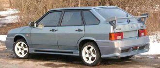
General diagram of the VAZ 2109
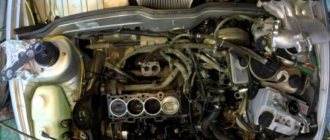
The vehicle was equipped with engine 21083. Its displacement was 1.5 liters, power was measured at 79 hp. The motor is located across the engine compartment (pictured below). The history of the VAZ 2109 brand dates back to 1988. The car is a modernized analogue of the 2108 model and is distinguished by the presence of additional two doors in the rear.
The ability to fold the rear row seats, thereby expanding the trunk capacity, turns the Nine into a family car. There are also cars (mostly they belonged to the first releases) that were equipped with a 2108 engine, the displacement of which was 1.3 liters and the power was 64 hp.
The disadvantage of such a motor is that if the timing belt breaks, it will become a serious problem and lead to expensive repairs. A modification of the car was intended for export, which was equipped with a 1.1-liter 21081 engine with a power of 54 hp.
VAZ 21099 | Engine compartment
Engine compartment
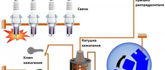
4 cylinder engines
View of the engine compartment of an Audi 80 with a 66 kW engine and a Mono-Motronic fuel mixture preparation system
In the engine compartment of an Audi 80, equipped with an 85 kW engine and a Digifant mixture preparation system, you see the following components and parts
5 cylinder engine
Engine compartment of a car with a classic 5-cylinder engine with a power of 98 kW and a KE-III-Jetronic fuel mixture preparation system
6 cylinder engine
Audi 80 with a 6-cylinder V-engine with a power of 128 kW; the engine compartment of the 110 kW 6-cylinder engine is almost the same
automn.ru
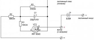
VAZ 2109 injector diagram: how it works
In 1997, they began producing 2109-20 cars, which are equipped with an engine with a distributed injection system (injector). This improves their efficiency, environmental and traction performance. Distributed injection is so called because fuel is injected directly into each cylinder by a separate injector.
Such a system makes it possible to somewhat reduce the toxicity of exhaust gases, as well as improve the driving performance of the 2109 car. Today, there are injection systems without feedback and with feedback. Both presented systems can include domestic and imported components. Each system has its own design, repair and diagnostic features.
I would just like to note the main principles of the design, normal operation, engine repair (if necessary) and subsequent diagnostics of the fuel injection system (the VAZ 2109 injector diagram is presented below).
The automotive fuel injection system, which has feedback, is used mainly on export VAZ 2109. The exhaust system of these cars is equipped with a catalytic converter for exhaust gases and an oxygen sensor. It provides feedback. Using an oxygen sensor, the oxygen concentration in already exhaust gases is monitored.
Next, the electronic control unit (ECU) of the vehicle, according to its signals, maintains the appropriate ratio of fuel and air, that is, one at which the special converter works extremely efficiently. The injection system, in which there is no feedback, is not equipped with a converter and an oxygen sensor.
Their function (regulating the concentration of CO in already completely exhausted gases) is performed by a CO potentiometer. They also do not use a gasoline vapor recovery system.
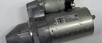
Features of the engine compartment
Let's find out what is dangerous under the hood for the operation of the wiring and the consumers it connects to the electrical network.
First of all, you should realize that all the most important components and assemblies that have high physical and chemical indicators are concentrated in this enclosed space:
- The power unit is a source of increased heating of nearby components and assemblies;
- Power supply system – explosive vapors of the air-fuel mixture;
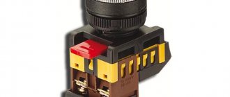
- Power elements of the electrical circuit - numerous electrical connectors and connections: relays,
- electric motors for windshield wipers and washers,
- headlight ignition units or self-installed fog lights to improve visibility on the road.
Therefore, if the technical parameters of the wires have deteriorated, as evidenced by oxidation of contacts, delamination of insulation, numerous twists, etc., it must be replaced as quickly as possible. Of course, unless you have a Finnish VAZ 2109 wiring, which initially has better parameters.
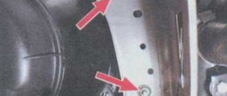
An example of the correct installation of new wiring in the engine compartment
Tip: be sure to use the wiring diagram when working in the engine compartment. This will prevent errors from occurring. And you can learn how to use it correctly from the video offered in the article.
Every VAZ 2109 owner should have a similar diagram
VAZ 2109 stove diagram: improvement options
The design and operation of the VAZ 2109 stove does not imply any complex procedures. However, the factory heater most often cannot distribute hot air evenly to the feet and onto the windshield. The modernization carried out on the VAZ-2114, contrary to expectations, could not solve this problem. However, there are no hopeless situations, and the presented diagram of the VAZ 2109 stove will help everyone who has the desire and time to solve this problem with their own hands.
In the process we will need:
- polystyrene foam and bitoplast;
- silicone or acrylic sealant;
- set of screwdrivers and keys;
- container for collecting coolant;
- sheet of copper or aluminum.
Let's get started:
- First you need to drain the coolant into a special separate container. Any liquid remaining in the radiator should be removed using a hose and funnel. Carefully remove the air ducts and, be sure to pay attention to possible misalignment of the holes that are located in the panel with the stove nozzles. If the misalignment exceeds 50%, you need to cut the interior heater.
- Next, having previously marked the connectors of the switches and light bulbs, remove the instrument panel. We disconnect the steering wheel, steering column trim and steering column switches. Next, we dismantle the heater: unscrew the 4 M10 nuts, disconnect the wire connector and all connectors on the heater body.
- Disconnect the radiator hoses and remove the heater valve cable latch. Next, carefully remove the heater, after unscrewing the two fan screws. Remove the radiator by unscrewing the three bolts. Be careful - there may still be coolant left here.
- Then make turbulators. These are special plastic spirals that increase the heat transfer of the radiator. “According to the rules,” they should be installed at the factory, but most often they are not. To make them yourself, you need to cut aluminum or copper plates, the width of which is 6 mm and the thickness is 1.5 mm. One side of such a plate should be clamped in a drill, and, at the same time, the other, using a vice, should be twisted into a spiral.
- Carefully inspect the bottom of the heater. Make sure there are no deformations, displacements, breaks or other defects. Then disassemble the stove by separating the body into two halves. To do this, use a screwdriver to open the latches and then unscrew the screw under the central nozzle. Remove the damper control levers.
- Carefully inspect the inside surface of the stove. If the foam has come loose, carefully glue it back, you can add strips of bitoplast. The housing should be made as airtight as possible. Adjust the center shutter.
- Before you begin assembling the heater, be sure to lubricate the places where the dampers are attached with a special grease. At the same time, when connecting the halves of the case, apply silicone or acrylic sealant to the connector. The heater should be assembled in the reverse order of disassembly. If there is deformation on the bottom wall, fill the gap with sealant.
- There should be no gaps between the stove body and the radiator. In the places where the housing is connected to the radiator, bitoplast should be glued. Next, you need to balance the fan impeller by winding wire around the blades. The wires must be routed through a special rubber plug located in the heater housing.
- Be sure to adjust the travel of the dampers. You need to be guided by the fact that the levers should always be clearly fixed in their extreme positions. Adjustment must be carried out by selecting the positions of the braid. Next, adjust the stove tap. You should choose a position in which the tap will not close completely.
- It is necessary to lubricate the hoses and radiator tubes with sealant before installing them. New clamps should be used. When the assembly is completed, you have filled in the coolant and warmed up the engine, you should tighten the clamps again. Before installing the instrument panel, you need to glue foam and bitoplast to the inlet holes of the nozzles.
Electrical diagram of VAZ 2109: required reading
“Nines” are one of the most popular domestic front-wheel drive cars in Russia. They are inexpensive and relatively easy to repair. Often they are serviced by the owners themselves, vehicles are tuning items, they turn into a hobby for their owners. Owners install new equipment on their cars. The electrical circuit diagrams below will be very useful during repairs.
The VAZ 2109 electrical diagram will always help car owners check which instruments and devices are out of order. To find out, you need to check them with a “tester”. Having identified any problems, you can repair the machine yourself.
Russia Cars
Rice. 1–2. Engine compartment of VAZ-2109 (top view):
1 – engine 2 – washer reservoir 3 – air filter 4 – fuel pump 5 – vacuum booster
6 – brake master cylinder 7 – relay and fuse block 8 – expansion tank 9 – battery 10 – ignition distributor
Rice. 1–3. Engine compartment of VAZ-2109 (bottom view):
1 – engine 2 – starter 3 – gearbox 4 – muffler exhaust pipe 5 – stabilizer 6 – front suspension arm 7 – front wheel drive 8 – engine oil sump 9 – brace
Cylinder head and valve mechanism (device features) The main dimensions of valves, guide bushings and valve seats are given in Fig. 2-44. Rice. 2-44. Main dimensions of valves, guides and valve seats. The cylinder head is cast from aluminum.
Checking the rear axle beam Carefully check the technical condition of the beam, especially when repairing a car that has suffered an accident. A deformed beam can cause rear axle noise and accelerated tire wear. De.