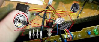
The Hall sensor (current, phase) records fluctuations in magnetic fields, especially those arising with currents, and their intensity, which is required in an extremely wide range of devices for monitoring the position of their nodes. In a smartphone, current sensors ensure the operation of the compass and smart cases. In cars, the angle of camshafts, crankshafts, ignition sparking moment, wheel rotation parameters, and approach to objects are measured. Increasingly, phase sensors are installed instead of a reed switch. Let's look at what a Hall sensor is, how it works and the types with a description of where they are used.
Example of using an analog element
Let us consider, as an example, the design of a current sensor whose operation is based on the Hall effect.
Simplified circuit of a current sensor based on the Hall effect
Designations:
Read also: How to choose trousers for a blouse
- A is a conductor.
- B – open magnetic conductor ring.
- C – analog Hall sensor.
- D – signal amplifier.
The operating principle of such a device is quite simple: the current passing through the conductor creates an electromagnetic field, the sensor measures its magnitude and polarity and produces a proportional voltage UDT, which is supplied to the amplifier and then to the indicator. https://www.youtube.com/watch?v=fmLs9WsKx3I
Advantages and disadvantages
Pros:
- universality (they simultaneously determine position, direction, and so on);
- wear resistance. There are no moving parts, they are solid state, rugged devices, providing extreme durability;
- almost complete independence from the need for maintenance;
- The Hall effect current sensor operates under vibrations, in dusty, humid, aggressive conditions, and at high temperatures.
Minuses:
- standard devices have a maximum distance to the measured current of about 10 cm. But it all depends on the magnet: if it is powerful and creates a wide field, then the distance increases;
- a characteristic “disease” is accuracy, since there is a dependence on the magnetic field, and other external similar phenomena can introduce distortions. The same applies to high temperatures, since they change the resistance of conductors, and accordingly, the mobility of charge carriers, but here sensitivity suffers. However, this is rare or the effect is negligible; in general, it does not particularly affect the work.
Hall Sensor
Rain sensor, liquid level sensor, temperature sensor - also known as a thermometer. Everything seems to be clear: the rain sensor shows the presence of rain, the liquid level sensor shows, oddly enough, the liquid level; thermometer - from Greek. – heat and measure, shows temperature. But what is this strange name: Hall sensor?
Where it all began
This was back in the 19th century. American physicist Edwin Hall discovered a very strange thing... He took a plate of gold and began to pass direct current through it. In the picture I marked this plate with faces ABCD.
So, when he passed direct current through faces D and B, he brought a permanent magnet perpendicular to the plate and do you know what he discovered? Potential difference on faces A and C! Or, more simply, tension. This effect was named after this scientist.
As soon as he made this discovery, they soon began to make radioelements based on this effect. In order not to bother with the name, they named it after the one who discovered this effect - in honor of Hall. Therefore, radioelements based on the Hall effect are called Hall sensors.
Linear Hall sensors
What does the voltage on faces A and C depend on? Mainly from a magnetic field created by either a permanent magnet or an electromagnet; the thickness of the plate, as well as the strength of the current flowing through the plate itself. Thanks to these parameters, using a Hall sensor, devices were built that made it possible to measure the current strength in a conductor without touching the wire itself, for example, current clamps
as well as instruments with which you can measure the magnetic field strength. Hall sensors used in these devices are called linear, since the voltage on the Hall sensor is directly proportional to the measured magnetic field parameters.
Linear sensors, as I already said, can be used in current clamps. They allow you to measure current ranging from 250 mA to several thousand Amperes.
Read also: How to choose a coat for a man
The biggest advantage in such current clamps is the absence of mechanical contact with the measured circuit.
In other words, Hall effect current meters are much safer than shunt and ammeter based meters, especially when the circuit current is high, which is often found in industrial installations.
Digital Hall sensors
The developers didn't stop there. As soon as the era of digital electronics arrived, various logic elements began to be placed in one housing along with a Hall sensor. It all looks something like this:
As a result, the industry began to produce Hall sensors for digital electronics. Basically, such sensors are divided into three types:
Unipolar. They react only to one magnetic pole. No attention is paid to the opposite magnetic pole. That is, we bring, for example, the south pole of the magnet, the sensor works. He doesn't care about the magnetic north pole.
Bipolar. This is where it gets more interesting. We bring the magnet to one pole - the sensor works and continues to work even when we remove the magnet from the sensor. In order to turn it off, we need to apply a different magnet polarity to it.
Omnipolar. These sensors don’t care which pole they turn on and off. Let it be at least southern or northern.
How to make it yourself
To make a simple DH with your own hands, you will need:
- Ferrite ring.
- Conductor for current.
- Hall element (ACS 711 chip, for example).
- Differential amplifier.
It is necessary to cut a gap in the ring in which the Hall element will be located. It will need to be connected to a differential amplifier, which is a special op-amp with negative feedback.
If the change in induction is a kind of “error,” then the op-amp acts as an error amplifier, as shown in the circuit diagram of the connection in Figure 1.
Rice. 1. Schematic diagram of connecting the Hall element.
Instead of an amplifier, you can install a microcontroller and connect it through a limiting resistor to the output of the ACS 711 microcircuit in ADC mode. Then you can connect a field-effect transistor to another pin of the microcontroller and you will get a pulse generator that can be used in pulse-width modulation mode, for example.
Purpose of DH and principle of its operation
DH have many advantages, among which are:
- small sizes;
- rectangular format of the electrical signal, which makes it possible to instantly dial a specific constant without any jumps or bursts.
Among the disadvantages of DH are:
- excessive sensitivity to interference from ELM fields arising in the power supply chain;
- higher cost of DC compared to a magnetoelectric device, which at the same time has greater reliability (from a theoretical point of view).
In a conventional understanding, DHs can be divided into 2 groups: linear and logical. In other words, in one of the sensors the output implies linearity, in the other - logic.
BSK ignition circuit
For example, a linear sensor is used to calculate small shifts or to design other, less simplified devices. In addition, such a DC can be used as an ultra-sensitive component of a chemical-based voltage regulator.
The purpose of the logical sensor is to calculate the presence of any connections with magnetic properties, which is implemented by the sensitive area of the DC.
Attention. This same unique feature of the controller can be used to calculate the final position of the metal component, as well as the amplitude of rotation of the impeller or a special pole magnet.
The most important thing in the use of DC is well-functioning and proven production over the years, because only in this way is the complete and undoubted reliability of the product ensured.
Magnetic sensors are one of the most common devices in the automotive industry. Born in the era of electro progress, they have remained popular to this day.
The relationship between magnet and current, expressed by the fact that the transformation of momentum is always associated with the emergence of a magnetic field, has led to today's realities. In other words, control of current changes in automotive ignition systems is regulated using DC.
Modern hall sensors have completely replaced the old contact group of distributors, which was often responsible for malfunctions in the ignition system. Hall sensors, on the contrary, although they can also fail, cope with their functions much better.
DH is an essential element of a modern contactless ignition system. In addition, these sensors have found application in other automotive systems. For example, they are used as revolution counters - tachometers, but always in conjunction with permanent magnets.
Modern distributor
DCs consist, as mentioned above, of a hall plate and a magnet. However, this is not an axiom, since there are DCs without a built-in magnet.
The functioning and purpose of DC can be easily explained by its composition. On a rectangular semiconductor, several square millimeters in size, or a film made of crystalline material, there are 4 electrodes. They are designed to supply current and retrieve information.
Working principle of the hall sensor
To avoid accidental mechanical failures, the semiconductor material is mounted on a durable substrate, and the film is treated with a dielectric substance.
To ensure the best effect, the thickness of the sensor plate or film is made as small as possible.
DCs are used for non-contact monitoring of the magnetic zone. In some cases, it is possible to use a DC with a built-in ferrite rod, which allows you to significantly increase the efficiency of the regulator.
Another way to imagine the operation of a hall sensor is as follows.
- The DC has a permanent magnet that forms a magnetic zone.
- The semiconductor plate crosses this same field, and a transformation is formed - closing the gap of the tooth located on the camshaft.
This very tooth is called a benchmark (in geodesy - a sign, a mark).
- So, this very point at the moment of contact forms a current pulse supplied to the ECU.
- The transmitted impulse depends entirely on the amplitude of rotation of the camshaft. This means that it arrives at different time intervals.
- The impulse, as mentioned, goes to the ECU.
- The latter decodes the pulse, thus determining the TDC position in the 1st cylinder of the engine.
- Only after this is permission given for fuel to enter the combustion chamber with its subsequent ignition.
It is noteworthy that a similar sensor in a diesel engine functions somewhat differently. The fuel in this case is heavier, which determines the difference. The diesel hall sensor is more needed to control the passage of the TDC pistons. Thus, the ratio of the shafts to each other is set with the greatest accuracy.
Manifestation of malfunction and possible causes
Irregularities in the operation of household farms can be detected by the following indirect signs:
- There is a sharp increase in fuel consumption. This is due to the fact that the fuel-air mixture is injected more than once during one crankshaft rotation cycle.
- Manifestation of unstable engine operation. The car may begin to “twitch” and a sharp deceleration occurs. In some cases, it is not possible to reach a speed of more than 50-60 km/h. The engine stalls during operation.
- Sometimes the failure of the sensor can lead to the transmission being locked, without the ability to shift it (in some models of imported cars). To correct the situation, a restart of the engine is required. In case of regular such cases, one can confidently state that the DP has failed.
- Often, a breakdown can manifest itself in the form of the disappearance of the ignition spark, which, accordingly, will make it impossible to start the engine.
- The self-diagnosis system may experience regular failures, for example, the check engine light will come on when it is idling, and the light will go out when the speed increases.
It is not at all necessary that the listed factors are caused by the failure of the DP. There is a high probability that the malfunction is caused by other reasons, namely:
- ingress of debris or other foreign objects onto the DP housing;
- the signal wire has broken;
- water has entered the DP connector;
- the signal wire is shorted to ground or the on-board network;
- the shielding sheath on the entire harness or individual wires is torn;
- damage to the wires supplying power to the DC;
- the polarity of the voltage supplied to the sensor is reversed;
- problems with the high-voltage circuit of the ignition system;
- problems with the control unit;
- the gap between the DC and the magnetic conductive plate is incorrectly set;
- Perhaps the reason lies in the high amplitude of the end runout of the camshaft gear.
Purpose of DC in the car ignition system
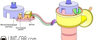
Having understood the principle of operation of the Hall element, let's consider how this sensor is used in the contactless ignition system of the VAZ line of cars. To do this, let's look at Figure 5.
Rice. 5. Principle of the SBZ device
Designations:
- A – sensor.
- B – magnet.
- C – plate made of magnetically conductive material (the number of protrusions corresponds to the number of cylinders).
The operating algorithm of such a scheme is as follows:
- When the chopper-distributor shaft rotates (moving synchronously with the crankshaft), one of the protrusions of the magnetically conductive plate takes a position between the sensor and the magnet.
- As a result of this action, the magnetic field strength changes, which causes the DC to operate. It sends an electrical impulse to the switch that controls the ignition coil.
- The voltage required to form a spark is generated in the Coil.
It would seem nothing complicated, but the spark must appear at a certain moment. If it forms earlier or later, it will cause a malfunction of the engine, even stopping it completely.
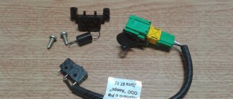
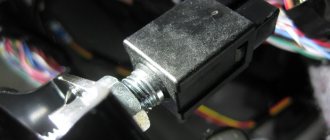
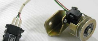
Appearance of the Hall sensor for SBZ VAZ 2110
Replacement
Let's look at the standard procedure for replacing a VAZ hall sensor. The process is simple even for novice car enthusiasts.
The procedure for replacing the Hall sensor:
- Remove the distributor and dismantle its cover.
- Align the marks of the gas distribution mechanism and crankshaft.
- Remove the fasteners with a wrench. In this case, it is recommended to mark and remember (take a photo with a smartphone) the location of the distributor.
- Clamps and stoppers in the housing are also dismantled.
- Remove the shaft from the distributor.
- Disconnect the terminal contacts, unscrew the mounting bolts, and pull out the detector through the slot.
- Connect the sensor correctly - proceed in reverse order.
There is no connection diagram in the car as such, since the sensor has a power cable with a plug, that is, the pinout is already there, and the chip is equipped with “foolproof protection” and keys (protrusions) that make incorrect installation impossible. The detector box has holes for mounting bolts.
In other devices, the Hall effect sensor is soldered according to the location of the legs and contacts under them on the board. If you take a “bare” sensor, however, and if there is a housing, the arrangement of contacts is similar. The required leg for soldering to the board is determined simply, as in the diagram below.
Digital Hall sensors
As soon as the era of digital electronics arrived, various logic elements began to be placed in one housing along with a Hall sensor. We have already reviewed the simplest Hall sensor on a Schmitt trigger above and it looks like this:
In fact, such a sensor has only two output states. Either the signal is present (logical one) or it is not (logical zero). The hysteresis on the Schmitt trigger simply eliminates frequent switching, which is why it is always used in digital Hall sensors.
As a result, the industry began to produce Hall sensors for digital electronics. Basically, such sensors are divided into three types:
Unipolar
They react only to one magnetic pole. No attention is paid to the opposite magnetic pole. For example, we bring the south pole of the magnet and the sensor will work. It will not react to the north magnetic pole.
Bipolar
We bring the magnet to one pole - the sensor will work and will continue to work even when we remove the magnet from the sensor. In order to turn it off, we need to apply a different magnet polarity to it.
Types and scope of application
Despite the variety of elements that use the Hall effect, they can be divided into two types:
- Analogue, using the principle of converting magnetic induction into voltage. That is, the polarity and voltage directly depend on the characteristics of the magnetic field. Currently, this type of devices is mainly used in measuring technology (for example, as current, vibration, rotation angle sensors).
Hall effect current sensors can measure both AC and DC current - Digital. Unlike the previous type, the sensor has only two stable positions, indicating the presence or absence of a magnetic field. That is, operation occurs when the intensity of the magnetic field has reached a certain value. It is this type of device that is used in automotive technology as a sensor for speed, phase, camshaft position, as well as crankshaft, etc.
It should be noted that the digital type includes the following subtypes:
- unipolar - triggering occurs at a certain field strength, and after it decreases, the sensor returns to its original state;
- bipolar - this type reacts to the polarity of the magnetic field, that is, one pole turns the device on, and the opposite pole turns it off.
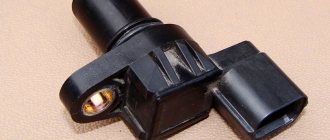
Appearance of a digital Hall sensor
As a rule, most sensors are a component with three pins, two of which are supplied with bi- or single-pole power, and the third is a signal one.
Connecting large electrical loads
The output power of the Hall sensor is very low (10–20 mA), as a result of which it cannot directly control high electrical loads. The problem is solved quite simply: the connection is made by adding an NPN transistor to the device, through which current flows to the output. The specified part acts as a receiver; when it is saturated, it is activated as a switch. The transistor grounds the output contact, thus closing it when the flux density of the set values for “on” increases.
There are various configurations of the transistor switch, but the main thing is that the device provides a 2-cycle output, allowing it to draw the required current to control large loads.
Repair
There is no point in repairing Hall sensors, since the cost of this will exceed its cost, which is in the range of $3–5.
If, out of curiosity, someone wants to do repairs, then you can try to do this for automotive products, but the repair will not concern the very core of the sensor, but the “chip” and the cable: the capacitor often burns out, it and the wires can be resoldered. The cause of the malfunction may lie in soured contacts; they are cleaned.
Main types
Hall sensors are divided into two categories:
- with analog operating principle (bipolar). Such a DC converts polar induction into voltage. The readings of the node depend on its polarity, as well as the field strength. The installation distance of the unit affects its characteristics;
- with digital (unipolar). A Hall sensor with a similar operating principle makes it possible to detect the presence/absence of a field - at the moment the conditional limit is reached by induction, the node displays “0”/”1″, which is logical.
Signs of trouble
Basic:
- the power unit has problematic starting or does not start at all;
- idle operation of the power plant is accompanied by interruptions/jerks;
- jerking of the car while driving at high/high speeds;
- engine stops running while driving.
The presence of one/several signs is a prerequisite for engine diagnostics. Symptoms such as these may indicate that the DC is faulty.
Test your device yourself
The active use of this device in cars means that if certain malfunctions or malfunctions occur in the internal combustion engine, there may be an urgent need to check the Hall sensor with your own hands. Before starting work to disconnect the cable connector that is connected to the device, be sure to turn off the ignition!
Ignoring this rule may damage the Hall sensor. It must be added that checking the device using a test lamp is also unacceptable.
- One of the fastest ways to check is to install a known-good replacement sensor on the car. If the signs of malfunction disappear after installation, then the cause is obvious.
- The second method that is suitable for checking the sensor in the ignition system is to check for the presence of a spark when the ignition is turned on. Additionally, you will need to connect the ends of the wire to the required outputs on the switch.
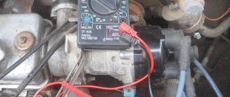
- For the most accurate diagnosis, it is best to check the device using an oscilloscope. Also, under certain conditions, the sensor is checked using a multimeter. The specified multimeter is switched to voltmeter mode, and then connected to the output contact on the sensor. A working Hall sensor will give readings from 0.4 Volts to 3. If the readings are below the minimum threshold, then there is a high probability of sensor failure.
If such a device is used in a structural unit, then it must be monitored very carefully. Remember to carry out frequent and regular checks and preventative measures for the circuit that is responsible for the connection.
This is interesting! All about semiconductor diodes.
When servicing, try not to damage the design of the device. Therefore, in order to prevent its damage, the device must be disconnected from the power supply after turning off the ignition. Thanks to this, you will not allow current surges, and therefore the device will not break. In most cases, non-working units are not repaired, since in practice repairs are completely useless. A broken device is simply disposed of and a new one is put in its place.
The key advantage of Hall sensors is that, subject to the permissible operating current and voltage values, it can be enough for a huge number of switches on and off of phones, smartphones, laptops and other devices. Unlike a reed switch, the device does not have electromechanical contacts, which wear out quickly.
So, we briefly talked about what a Hall sensor is, on what principle it works, and what function it can perform in cars, as well as mobile phones and other types of digital equipment.
Hall Sensor.
Application of Hall sensors
Currently, the scope of application of Hall sensors is very extensive and is becoming wider and wider every year. Here are the main applications:
Application of linear sensors
- current sensors
- tachometers
- vibration sensors
- ferromagnetic detectors
- rotation angle sensors
- non-contact potentiometers
- brushless dc motors
- flow sensors
- position sensors
Application of digital sensors
- speed sensors
- synchronization devices
- car ignition system sensors
- position sensors
- pulse counters
- valve position sensors
- door lock
- flow meters
- contactless relays
- proximity detectors
- paper sensors (in printers)
Scheme for practical repetition
A simple circuit using a Hall sensor, used to register the opening of a door, is not difficult for self-assembly. The advantage of using a sensor is that its operation does not require mechanical contact, such as a reed switch. The sensor is placed on the door frame and the magnet is on the door. The circuit is based on the MH 183 sensor and the CD 4093 chip . A nine-volt voltage source is responsible for power supply.
When exposed to magnetic flux, the transistor switch is in an active state. The signal from the sensor enters the input of the microcircuit and prohibits the operation of its generator. LED1 is lit. If the door opens, the magnetic force acting on the sensor weakens or disappears, and the generator in the chip starts and the LED goes out. Resistor R1 is designed to protect the Hall converter from reverse voltage breakdown. The Hall sensor has found its application in many areas and is an indispensable assistant for a person in everyday life. It is thanks to him that so-called “smart” devices exist.