An electromagnetic device called a Hall sensor (hereinafter referred to as Hall sensor) is used in many devices and mechanisms. But its greatest application was found in the automotive industry. In almost all models of the domestic automobile industry (VAZ 2106, 2107, 2108, etc.), the non-contact ignition system for a gasoline engine is controlled by this sensor. Accordingly, when it fails, serious problems arise with the operation of the engine. In order not to make mistakes when diagnosing, it is necessary to understand the principle of operation of the sensor, know its design and testing methods.
Design and principle of operation
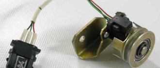
The controller design consists of the following parts:
- magnet;
- rotor;
- chip;
- plastic housing;
- conclusions;
- magnetic circuits.
The sensor operates based on the Hall effect. The principle of operation of the element is as follows:
- The rotor has four teeth that rotate while the engine is running.
- Pulses are constantly read.
- The received information in the form of a signal is sent to the switch.
- The pulse arrives at the installed coil.
- An increased voltage of 22–25 kV is supplied to the spark plugs.
The type of functioning is not complicated.
Description of the operating principle of the sensor
The G8 electronic ignition system consists of the following elements:
- The main distributor of the ignition system, in which a photoelectric sensor is installed that records the position of the camshaft (Hall sensor).
- High voltage coil.
- Electronic control unit - switch.
- High voltage wires.
The high voltage coil has two windings. The primary is connected to the circuit with the battery through a switch, relay and ignition switch, while the circuit is constantly closed. When the ignition moment is approaching in one of the cylinders and the piston is close to top dead center, the Hall sensor, mounted on the same axis with the camshaft, records this moment and signals it to the switch. It should be noted that in more modern schemes this function is performed by the crankshaft position sensor.
In modern circuits, the crankshaft position sensor functions as a hall sensor
The commutator, having received an impulse, breaks the circuit of the primary winding of the coil. In this case, a high voltage electromagnetic pulse is generated in the secondary winding, which has a much larger number of turns than the primary. It is supplied again to the ignition distributor through one high voltage wire, reaching the central contact of the slider. The latter transmits an impulse to one of the four cylinders, in which the fuel mixture needs to be ignited. After completing the cycle, the commutator restores the circuit of the primary winding of the coil and waits for the next signal from the Hall sensor.
As can be understood from the principle of operation of the circuit, the VAZ 2108 photoelectric Hall recorder is a key element of the circuit; without its normal operation, there will be no spark discharge on the spark plugs. Therefore, in the event of a car malfunction such as the disappearance of a spark, you need to immediately check the operation of two elements: the switch and the photoelectric sensor. In the first “eights” and “nines”, it was the switch that most often failed due to an imperfect design.
Since this problem was subsequently corrected, the main cause of ignition system failure is usually a malfunction of the recorder. The latter cannot be repaired, and in case of incorrect operation, the Hall sensor must be replaced.
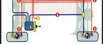
Connection diagram
The figure shows a basic electrical drawing for the VAZ 2108 and 2109 with pinout of contacts.
The ignition system operates as follows:
- The wire transmits voltage to the sensor from the switch through the red wire.
- A magnet creates a field.
- An impulse is supplied to the switch through the green wire.
Using a Hall element, the voltage directed to the high-voltage coil is regulated.
Hall sensor on a VAZ 2108 car
The electronic ignition system installed in VAZ 2108-09 cars, in its operating principle, is a transitional option from a cam contact system to a fully electronic ignition, in which there are no moving mechanical parts.
In terms of its performance characteristics, such an ignition circuit is also in the middle between the old and new systems, having its own disadvantages inherent only to it. These shortcomings somewhat affect the reliability of the ignition; you need to periodically pay attention to the condition of the switch and Hall sensor of the VAZ of the eighth and ninth models.
Symptoms of a problem
Over time, the device becomes unusable. This can be recognized by the following signs:
- the engine runs poorly or stalls;
- the engine does not idle;
- car detonation is observed;
- While driving, the engine turns itself off.
Problems are not always serious. Sometimes the cause is simple oxidation of the contacts. It is enough to move them to restore engine operation. Such symptoms appear due to weakening of the sensor fasteners. To do this, it needs to be tightened. It happens that the reason lies in a short circuit in the wiring.
Purpose of DC in the car ignition system
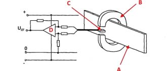
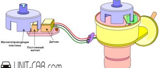
Having understood the principle of operation of the Hall element, let's consider how this sensor is used in the contactless ignition system of the VAZ line of cars. To do this, let's look at Figure 5.
Rice. 5. Principle of the SBZ device
Designations:
- A – sensor.
- B – magnet.
- C – plate made of magnetically conductive material (the number of protrusions corresponds to the number of cylinders).
The operating algorithm of such a scheme is as follows:
- When the chopper-distributor shaft rotates (moving synchronously with the crankshaft), one of the protrusions of the magnetically conductive plate takes a position between the sensor and the magnet.
- As a result of this action, the magnetic field strength changes, which causes the DC to operate. It sends an electrical impulse to the switch that controls the ignition coil.
- The voltage required to form a spark is generated in the Coil.
It would seem nothing complicated, but the spark must appear at a certain moment. If it forms earlier or later, it will cause a malfunction of the engine, even stopping it completely.
Manifestation of malfunction and possible causes
Irregularities in the operation of household farms can be detected by the following indirect signs:
- There is a sharp increase in fuel consumption. This is due to the fact that the fuel-air mixture is injected more than once during one crankshaft rotation cycle.
- Manifestation of unstable engine operation. The car may begin to “twitch” and a sharp deceleration occurs. In some cases, it is not possible to reach a speed of more than 50-60 km/h. The engine stalls during operation.
- Sometimes the failure of the sensor can lead to the transmission being locked, without the ability to shift it (in some models of imported cars). To correct the situation, a restart of the engine is required. In case of regular such cases, one can confidently state that the DP has failed.
- Often, a breakdown can manifest itself in the form of the disappearance of the ignition spark, which, accordingly, will make it impossible to start the engine.
- The self-diagnosis system may experience regular failures, for example, the check engine light will come on when it is idling, and the light will go out when the speed increases.
It is not at all necessary that the listed factors are caused by the failure of the DP. There is a high probability that the malfunction is caused by other reasons, namely:
- ingress of debris or other foreign objects onto the DP housing;
- the signal wire has broken;
- water has entered the DP connector;
- the signal wire is shorted to ground or the on-board network;
- the shielding sheath on the entire harness or individual wires is torn;
- damage to the wires supplying power to the DC;
- the polarity of the voltage supplied to the sensor is reversed;
- problems with the high-voltage circuit of the ignition system;
- problems with the control unit;
- the gap between the DC and the magnetic conductive plate is incorrectly set;
- Perhaps the reason lies in the high amplitude of the end runout of the camshaft gear.
How to check
If you suspect a sensor malfunction, you can diagnose it as follows:
- Using a working element. The power is disconnected from the main sensor and connected to a new device. Then the central ignition wire is removed and placed on a metal surface. This is done to visually record the spark. The ignition turns on. To simulate the operation of the screen, a thin metal object is moved near the magnet. If a spark appears noticeably, it means that the original sensor was faulty.
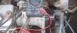
- Using a multimeter. First, it is switched to voltmeter operating mode. The meter wires are connected to the element. When you move a metal object inside the sensor, the operation of the screen will be simulated. If the device shows a voltage change ranging from 0.4 V to 11 V, then the element is working.
- By creating a simulation of a new sensor. Power is disconnected from the element. The central wire of the distributor is removed and placed on ground to observe the spark. At the next stage, contacts “3” and “6” are closed and a spark is observed. A sensor malfunction is confirmed if it slips.
If such a check indicates a breakdown, then the element must be discarded and a new one installed.
Replacement
When the check shows a malfunction of the sensor, then for removal you need to prepare a 10 mm wrench and a screwdriver. Procedure steps:
- Power is turned off from the device.
- The distributor is removed from the car.
- The device is placed on a workbench and the cover is removed.
- Carefully remove the boot with the slider.
- The plug screw is unscrewed.
- Remove the support plate screws.
- The vacuum corrector is dismantled. To do this, unscrew 2 screws.
- All wires are available.
- The sensor is removed along with the support plate.
- A new element is installed and installation is carried out in the reverse order.
During the replacement process, the entire internal space of the distributor must be thoroughly cleaned of dirt. As with flushing the carburetor, acetone is used for this.
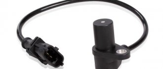
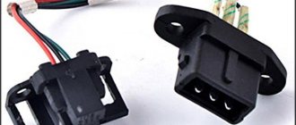
Where installed
The hall sensor is located inside the ignition distributor (distributor). The magnetic element is secured to the support plate, under the slider boot, with two screws. 3 wires come from it: red, green and black (positive, pulse, negative) and are connected to the block, which is secured with 1 screw at the exit from the distributor body. The pinout of the wires is in exactly this order.
Prices
For VAZ 2108–2109, the original number of the Hall device is product with article number 21080-3706800-00. If it is not available, pay attention to analogues. Possible options are presented in the table.
| vendor code | Manufacturer organization | Price in rubles |
| 21080-3706800-00 (original) | LADA | 590 |
| 21080370680082 (analog) | AVTOVAZ | 240 |
| GLSS133 (analog) | GALLANT | 230 |
| 21080370680000 (analog) | AUTO ELECTRONICS | 195 |
| 21080370680001 (analog) | AVTOVAZ | 190 |
| RK02008 (analog) | REMCOM | 150 |
The presented analogues are high-quality products that can be installed on a car.