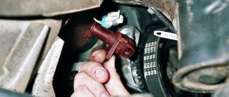
A modern car is now equipped with a variety of active safety systems, the list of which is growing every year. These also include a system to prevent wheel locking during braking - ABS (Anti-lock braking system).
ABS is one of the very first safety systems that began to be used on a car, and it is now found on almost all cars, from budget categories to premium ones.
Let's briefly consider the purpose of ABS - this system is needed so that the wheels do not lock during braking, but continue to rotate, albeit at a slower rate.
Thanks to this, the grip of the wheel on the road surface is not lost and the likelihood of the car skidding is completely eliminated, the car remains fully controlled by the driver.
ABS has been used in vehicles for a long time and has proven its effectiveness more than once.
This system works simply. There is an electronic unit that controls the deceleration rate of each wheel. And if one of them stops faster than others, the block reduces the force of fluid pressure in the brake caliper on this particular wheel, that is, the brake mechanism begins to act less.
You can read more about the ABS device and other information on this system here.
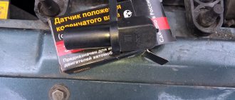
What is the ABS sensor for?
It is stated above that the ABS unit, popularly called the “brains” of the braking system, controls the speed of rotation of the wheels, so the design of this system could not be done without sensors.
They are the “sense organs” of this system and based on their readings the ABS functions.
The first anti-lock braking system used only one sensor, which was installed in the axle of rear-wheel drive cars.
But as ABS has improved, their number has increased; modern cars already use 4 sensors. This allows the system to monitor the rotation speed of each wheel individually.
IF A PROBLEM IS DETECTED
If the ABS self-diagnosis accurately identifies the faulty part of the system, the driver will need to make a decision - to replace the damaged element with a new one or repair the old one. It is worth mentioning right away that even an ABS check, if it was performed for the first time by a person without the proper experience and appropriate equipment, does not mean at all that the verdict “fault” is final.
So, if the system says that one of the sensors on the wheel is faulty, you should not rush to change it, you should first check all the contacts and wires leading to it - the problem often lies in these elements. If diagnostics of the anti-lock braking system indicate that its central unit is faulty, it must either be repaired by specialists or replaced if restoration is impossible. If the ABS diagnostic program points to the sensors, and all contacts are in order, the faulty device can be replaced with a new one yourself.
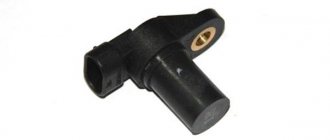
Types of sensors
There are three types of such elements, differing in their operating principle. The most common passive sensors are induction type.
The essence of their work comes down to a change in voltage due to the influence of a magnetic field. Their main disadvantage is the inability to determine the speed of rotation of the wheel at very low speeds.
The remaining two types are active.
One of them is magnetoresistive (rare). The principle of its operation is based on the magnetoresistive effect - the property of a semiconductor to change the trajectory of electrons when exposed to a magnetic field.
The second type of active sensor uses the Hall effect, in which electrons on a semiconductor wafer move to its edges when the magnetic field changes.
Briefly about the principle of operation
The ABS function simulates the harsh, repeated pressure on the brake pedal experienced by drivers of older cars on slippery roads. Electronics uses this method of braking much more efficiently, locking and “releasing” the wheels several times per second. The operating algorithm is as follows:
- During sudden braking, the control unit monitors the behavior of the wheels using sensors.
- If one or more wheels stop rotating, the ECU issues a command to a hydraulic valve that releases fluid from that circuit. The pads stop holding the disc and rotation resumes.
- By comparing the readings of all meters, the controller makes sure that braking is not complete and closes the hydraulic valve, and the wheel is blocked again. The cycle, lasting a fraction of a second, is repeated until the machine stops completely.
Important! If the functionality of one or more sensors is impaired, the ABS will fail entirely, since the electronic unit will not be able to compare the behavior of the wheels.
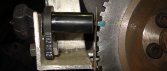
The latest generation ABS sensor is a coil with a semiconductor element installed in a stationary part of the hub. In the immediate vicinity of it, a toothed ring is attached to the brake disc, whose rotation is monitored by a sensor. It happens like this: the controller supplies voltage to the device, and it constantly changes the resistance due to the passage of a series of teeth on a rotating ring.
When the amount of electrical resistance becomes constant, the ECU regards this fact as wheel locking and turns on the above-described algorithm. If the element fails, the ABS system is completely disabled.
Sensor Features
There are several significant differences between passive and active types. They are called passive because they do not require voltage to operate; such a sensor itself generates electrical impulses, to which the electronic unit reacts. Active elements require voltage to be applied to them.
Passive elements are very simple in design and are very reliable. That's why they are so common, despite their shortcomings.
Active types of sensors use microcircuits in the design, which complicates the element and makes it more vulnerable. But they are highly accurate and do their job even at low speeds.
Since all types of sensors operate under the influence of a magnetic field, it alone is not enough in the design; another element is needed to which it would react.
The induction (passive) type uses a ferromagnetic alloy pulse gear ring mounted on the drive hub or shaft, as well as on the steering axle. Previously, it could also be mounted on the bevel gears of the main drive.
In active types, a magnetic pulse ring is used. In the case of a magnetoresistive sensor, this ring is divided into alternating sectors with permanent magnets of different polarities.
But the Hall sensor uses a regular magnetic ring, without any sectors, integrated into the wheel bearing.
How does ABS work?
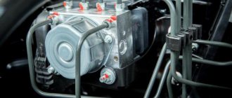
With the advent of the new braking system, vehicle safety during emergency braking has increased. The system began to be installed in the 70s. The ABS system includes a control unit, a hydraulic unit, wheel brakes and speed sensors.
The main device of the ABS is the control unit. It is he who receives signals from touch sensors in the form of the number of wheel revolutions and evaluates them. The data obtained is analyzed and the system draws a conclusion about the degree of wheel slip, their deceleration or acceleration. The processed information is sent in the form of signals to the magnetic valves of the hydraulic unit, which performs the control task.
Pressure is supplied from the brake master cylinder (MBC), which ensures the appearance of pressure in the brake caliper cylinders. Thanks to the pressure force, the brake pads are pressed against the brake discs. Regardless of the situation and the force the driver presses the brake pedal, the pressure in the brake system will be optimal. The advantages of the system are that each wheel is analyzed and the optimal pressure is selected, thereby preventing wheel locking. Full braking occurs due to the pressure in the brake drive system, regulated by ABS.
This is the principle of ABS operation. On vehicles with rear-wheel drive and all-wheel drive, there is only one touch sensor, which is located on the rear axle differential. Information about the possibility of blocking is taken from the nearest wheel, and the command about the required pressure is transmitted to all wheels.
The device that controls magnetic valves can operate in three modes:
- With the inlet valve open and the outlet valve closed, the device does not prevent pressure from increasing.
- The inlet valve receives the appropriate signal and remains closed, without changing the pressure.
- The exhaust valve receives a signal that the pressure is decreasing and opens, while the inlet valve closes and the pressure decreases as the check valve turns on.
Thanks to these modes, the pressure decreases and increases in a stepwise system. If problems arise, the ABS system is deactivated and the braking system operates without its participation. On the dashboard, the corresponding indicator indicates problems with ABS.
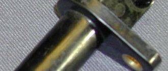
Inductive type element design
Since inductive sensors are the most common, their design will be considered in the future.
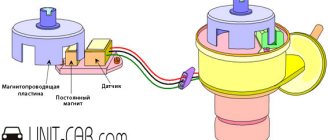
Such a sensor consists of an inductive coil, inside of which a magnetic core is placed. It is installed next to the toothed impulse ring, but so that there is a certain gap between them.
When the wheel rotates, the ring teeth pass through the magnetic field created by the core, which affects the magnetic flux, causing the alternating voltage value in the coil winding to change.
As a result, the speed of rotation of the wheel, and with it the pulse ring, affects the frequency and amplitude of oscillations of the output voltage on the coil. These parameters are fed to the “brains”, as a result of which they estimate the speed of deceleration of the wheel.
Problems with at least one of the ABS sensors can lead to a complete shutdown of the system. And although the braking system on the car will work, you can forget about the braking efficiency and safety that ABS provided.
Checking the quality of work performed
After replacing the sensor, its functionality is checked. To do this, it is enough to accelerate to a speed of 40 km/h on a flat, safe section of the road and perform sharp braking. If the car stops without pulling to the side, vibration is transmitted to the pedal and a specific sound of brake pads being activated is heard - the ABS system is operating normally.
Today you can easily find and buy any ABS sensors - from expensive original devices to analog parts at an affordable price. Remember that proper selection of system elements plays an important role in its uninterrupted operation. When choosing a sensor, study the manufacturer's instructions and make sure that it fits the car, and this review will help you replace the device yourself.
Causes of sensor malfunction
The induction sensor is characterized by its simple design and high reliability; malfunctions with it occur very rarely. The problem most often lies in the wiring through which signals are sent to the control unit.
Since the sensors and their wiring are located directly next to the wheels, over time the circuit may break or short out. Often, sensor failures occur due to oxidation of the contacts.
Due to the fact that after turning on the ignition on a car, ABS always undergoes self-diagnosis, during which the condition of all elements of the system is assessed, it is quite simple to identify problems with the sensors; if they occur, the warning light will constantly light up on the dashboard.
In total, there are 4 types of system behavior when a malfunction is detected:
- Self-diagnosis detects an error and ABS is disabled. This may be a sign of an error in the control unit, or a break in the wiring coming from the sensor;
- The system undergoes diagnostics, during which no problems are detected, but after this the ABS is turned off. This result usually results from problems with the wiring going to the sensors (oxidation, open circuit, short circuit, etc.);
- Self-diagnosis detects an error, but the system does not turn off and continues to operate. This usually indicates a break in the wiring on one of the sensors;
- ABS does not turn on. This can happen due to a broken wiring, or because the impulse ring is damaged, chipped or broken. This result can also be produced by a heavily worn hub bearing, which is why there is significant play in it.
Since malfunction of ABS often occurs due to wiring, it is quite simple to identify a faulty element and all you need is a multimeter.
Of course, it is better to check using an oscilloscope, since such a device makes it possible to visually assess the amplitude and frequency of voltage fluctuations in the sensor, but not everyone has one.
Next, we’ll figure out how to check the ABS sensor on different cars, although in general the procedure is the same, despite the fact that any type of sensor can be used on different models.
How to diagnose the ABS system
To obtain complete and reliable information about the state of the entire system, diagnostics should be carried out using special equipment. For this purpose, the manufacturer provides a special connector. After connection, the ignition is turned on and the test begins. The adapter issues error codes, each of which signals a breakdown of a specific component or element of the system.
A good model of such a device is Scan Tool Pro Black Edition from Korean manufacturers. The 32-bit chip makes it possible to diagnose not only the engine, but also all components and assemblies of the car. The cost of such a device is relatively low.
Diagnostics can also be carried out at service centers and service stations. However, even in garage conditions, if you have certain knowledge, identifying defects will not be difficult. To do this, you will need the following set of tools: soldering iron, tester, heat shrink and repair connectors.
The check is performed in the following sequence:
- the wheel being tested is jacked up;
- the control unit and controller outputs are dismantled;
- repair connectors are connected to the sensors;
- The resistance is measured with a multimeter.
A fully functional ABS sensor at rest has a resistance of 1 kOhm. When the wheel rotates, the readings should change; if this does not happen, the sensor is faulty. It should be remembered that different sensors have different meanings, so you need to study them before starting work.
Checking the ABS sensor with a multimeter
In addition to the device itself, you need to find a description of the sensor model. Further work is performed in the following sequence:
- The machine is placed on a flat, uniform surface, and its position is then recorded.
- The wheel is removed where the ABS sensor will be checked.
- The connector is disconnected and the contacts of both the sensor and the plug itself are cleaned.
- The wires and their connections are inspected for abrasions and other signs of damage to the insulation.
- The multimeter switch is switched to resistance measurement mode.
- The tester probes are applied to the output contacts of the sensor and readings are taken. Under normal conditions, the device display should show the number indicated in the sensor data sheet. If there is no such information, we take readings of 0.5 - 2 kOhm as the norm.
- Then, without removing the probes, the car wheel spins. If the sensor is working properly, the resistance will change, and the higher the rotation speed, the more the resistance changes.
- The multimeter is switched to voltage measurement mode and measurements are taken.
- At a wheel rotation speed of 1 revolution/sec. The indicator should be within 0.25 - 0.5 V. The higher the rotation speed, the greater the voltage.
- All sensors are checked in the same sequence.
In addition, the entire wiring harness is connected to each other to make sure there is no short circuit.
It should be remembered that the design and values of the sensors on the rear and front axles are different.
Based on the data obtained during measurements, the performance of the sensor is determined:
- the indicator is lower than normal - the sensor is unusable;
- a very low resistance value or near zero - short circuit of the coil turns;
- when bending the wiring harness, the resistance indicator changes - the wire strands are damaged;
- the resistance indicator tends to infinity - a break in the conductor or core in the induction coil.
You should know that if, during diagnostics, the resistance reading of one of the ABS sensors is very different from the others, it means it is faulty.
Before you start ringing the wires in the harness, you should find out the pinout of the control module plug. Then the connections between the sensors and the ECU are disconnected. And after that, you can start sequentially ringing the wires in the harness according to the pinout.
Checking the ABS sensor with an oscilloscope
An oscilloscope can also be used to determine the performance of ABS sensors. However, it is worth noting that this will require some experience in working with it. If you are one of the avid radio amateurs, then this will not seem difficult, but the average person may have a number of difficulties. And the main one is the cost of the device.
This device is more suitable for specialists and craftsmen of service centers and service stations. However, if you have such a device, it will be a good assistant and will help identify faults not only in the ABS system.
An oscilloscope is used to visualize the electrical signal. The amplitude and frequency of the current are displayed on a special screen, thanks to this you can obtain accurate information about the operation of a particular element.
So, the test begins using the same method as with a multimeter. Only at the multimeter connection point is an oscilloscope connected. And then the sequence is like this:
- the suspended wheel rotates at a frequency of approximately 2 - 3 revolutions per second;
- vibration readings are recorded on the instrument display.
After determining the integrity of one wheel, you should immediately begin checking on the opposite side of the axle. Afterwards, the data obtained is compared and conclusions are drawn based on them:
- provided that the readings are relatively identical, the sensors are in good working order;
- the absence of a step-like phenomenon when setting a smaller sinusoid signal indicates normal operation of the sensor;
- a stable amplitude with peak values not exceeding 0.5 V at the speeds mentioned above indicates the integrity of the sensor.
Checking without instruments
The performance of ABS sensors can also be checked by the presence of a magnetic field. To do this, take any iron object and apply it to the sensor body. When the ignition is turned on, it should be attracted.
In addition, you should carefully inspect the sensor itself and its installation location for damage. The wire should not have any abrasions, chips, insulation damage, etc. The sensor connector must be free of traces of oxidation.
It is important to know that the presence of dirt and oxidation can distort the signal from the sensor.
Check on Ford Focus 2
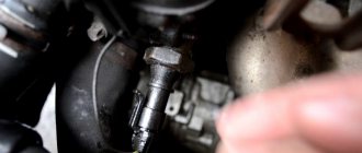
First, let's look at how the test is carried out on a Ford Focus 2. This car uses a Hall effect sensor and is located in the upper part of the wheel hub. It is easy to detect - just remove the wheel, unscrew and move the caliper to the side, and also remove the brake disc.
Before starting the inspection, be sure to check the tire pressure. It must be the same in all wheels, otherwise the pressure difference may affect the performance of the system.
To check the sensor on Focus 2, for ease of access, you should jack up and remove the wheel from the side being tested.
Next, disconnect the block of wires coming from the sensor. We visually assess the condition of the braid and wires; they should not show abrasions or other types of damage.
At the first stage, we check the resistance. To do this, switch the multimeter to ohmmeter mode and connect its probes to the terminals in the block.
On Focus 2, the sensor resistance when measured should be in the region of 1.3-1.4 kOhm.
But there is one nuance that is important to consider. During measurements, you should knead the wire, especially at bends.
The fact is that at the point where the wire is broken, the copper conductors can come into contact, and therefore the sensor can show normal resistance. And during crumpling and bending, contact is broken.
If the readings do not match, a measurement should be taken at the input of the wires to the sensor. This will reveal whether the problem lies in the sensor itself, or just in the wires.
If, when checking the resistance near the element, a discrepancy in resistance remains, then the sensor must be replaced.
In some cases, the cause of the problems lies in contamination of the semiconductor platinum of the Hall element. Therefore, you should remove the sensor itself and clean it.
In addition to the sensor wiring, you should also check the entire circuit for damage. To do this, you need to disconnect the wire block from the control unit.
Then we find out from the technical documentation for the car which terminals on the block correspond to which sensor, after which we connect a multimeter to the necessary connectors and measure the resistance.
If it does not meet the required parameters, you should look for a break in the area from the control unit to the sensor connection block.
Faults such as breaks or short circuits can be treated by replacing the wires. But if the element itself malfunctions, it is replaced.
If replacing the ABS sensor does not produce results
Having considered the available ways to check the ABS, it may seem that it is enough to identify the problematic sensor and replace it. Replacing the wiring may also seem like a solution.
However, in reality it is not so simple. Often, car enthusiasts are faced with the fact that even after replacing the ABS sensor, the system still does not work. By the way, this also happens in cases where the ABS was working normally, but after replacing the hub or wheel bearings the ABS light comes on.
In this case, computer diagnostics show that there is no signal from the ABS sensor. Next, the sensor is replaced, but the ABS system still does not work. Even if you remove the error using a scanner, after a few meters or after 1-2 braking the error lights up again.
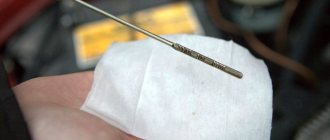
So, the reason in this case is not the sensor at all. Often the culprit is the way the signal is generated from the wheel rotation sensor. More precisely, in the case when the inducing element is the comb ring on the hub (ABS ring). The end part of the sensor itself is located near the comb, which is made of soft magnetic material.
We also recommend reading the article about why brakes or pads squeak when braking. From this article you will learn about the causes of squeaking brake pads and brakes, as well as how to eliminate squeaking pads when braking a car.
The gap between them is minimal, only from 0.2 to 0.8 millimeters. If dirt or stones adhere to this area, this will lead to a violation of the gap, displacement of the sensor, and destruction of the tip. Naturally, the signal will become weak. Also, the comb itself may become clogged, which causes failures.
Given this feature, before installing a new sensor, you must first check the gap and clean the comb with a solvent. When finished, check the gap size with a feeler gauge. It is not allowed to increase the gap by more than 1 mm. It is also important to inspect the elements for possible damage.
If you are not exactly sure, you can compare the parts with the same devices on another wheel. If damage to the wheel comb is detected, the element needs to be replaced.
Let us also add that the inducing element on some cars can be implemented in the form of a rubber ring or magnetic tape. There are magnetic plates inside the ring. It happens that during in-line repairs this ring is simply not installed. Naturally, the ABS system will not work without them.
As for the tape, it is easy to damage. This means that you need to work carefully, since if the belt is damaged, the ABS sensor will not work properly. It is also important to ensure that when replacing the wheel bearing, an element with an inducing ring is installed in the case where exactly such a design is provided on the car.
Diagnostic features for BMW E39
Next, let's look at the nuances of checking the ABS sensor on a BMW E39. This car already uses an induction element.
Diagnostics are carried out using the same methods as for Focus 2. That is, the resistance of the sensor, its wiring, as well as the circuit from the control unit are checked.
Since this car uses an induction type element, it is additionally possible to measure the output voltage.
To do this, switch the multimeter to voltmeter mode and connect it to the sensor wiring connectors.
Next, spin the wheel to approximately 50 rpm. In this case, the element being diagnosed will begin to generate electricity, the voltage of which should be around 2 V.
The need to replace the device
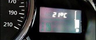
Malfunctions in the ABS system are indicated by a warning lamp located on the dashboard of the car. In normal mode, the indicator lights up when the engine starts and goes out after 3–5 seconds. If the controller behaves incorrectly - it turns on while the engine is running or blinks chaotically when the car is moving - this is the first sign of a sensor failure.
The ABS indicator should go out 3-5 seconds after starting the engine
Also, a possible device malfunction is indicated by:
- an error code appears on the on-board computer display;
- continuous wheel locking during heavy braking;
- absence of characteristic vibration on the brake pedal when it is pressed;
- the parking brake indicator lamp has been activated when the handbrake is off.
If any of these problems occur, the device should be fully diagnosed. It is not at all necessary to trust this question to highly paid car service technicians - checking the ABS sensor yourself takes little time and is done without expensive equipment. If diagnostics reveal that the device is broken, it will have to be replaced with a new one.
Design nuances of Lada "Priora", "Kalina"
Now let’s figure out a little how to diagnose and replace Lada cars of the Priora and Kalina models. These cars were taken as an example because they use drum brakes at the rear, and above we looked at how work is carried out with sensors that work with disc mechanisms.
Checking the sensors on Kalina or Priora is completely identical to those described. But this sensor still needs to be found. The element is installed in the rear wall of the hub, and the impulse ring is located inside the mechanism, under the drum.
Therefore, in order to assess its condition, you will have to remove the drum from the car, and immediately under it you will see the ring, as well as the protruding part of the sensor, which passes through the technological hole in the brake pad.
That is, by checking the condition of the ring, you can immediately look at and clean the sensor itself from dirt. And then we measure the resistance of the sensor and the entire circuit up to the “brains”.
How to change
According to the ABS scheme, all wheels of the car are equipped with sensors. The peculiarity of their replacement is that the elements installed on the front axle of the car are removed from the bottom of the body or from under the hood of the car. The rear sensors can only be accessed from below. This instruction describes the general principles of replacing the device. Note that this method is applicable to many foreign and domestic cars.
Tools
To change the sensor you will need:
- reliable jack;
- wheel wrench;
- a set of open-end and socket wrenches;
- hammer;
- flat screwdriver;
- metal conditioner WD-40;
- tester (multimeter).
Phased replacement
We will consider the step-by-step execution of work using the example of replacing a device installed on one of the rear wheels of a car.
- Let's park the car on a flat surface and activate the parking brake (handbrake). We will place wheel chocks under the wheels that are not involved in repair work. Remove the negative terminal from the battery.
- We dismantle the rear row of seats, the plastic trim of the threshold and the rubber door seal.
- Let's get to the sensor connector - bend the clamps and pull out the plastic trim in the area where the shock absorber is mounted. Let's disconnect the device.
View from the interior: 1 — connector; 2 — clamp; 3 — overlay; 4 - sensor wire
The wheel must be removed by installing safety supports under the bottom of the car.
View of the rear part of the hub: 1 — bracket; 2 - mounting bolt
View of the arch: 1 and 2 — sensor wire fixation points; 3 - plug
Attention! Before installing the trim elements, turn on the ignition and start the car engine. Only after making sure that the ABS indicator lamp behaves correctly (it goes out 3-5 seconds after the start) do we continue to work.
As a visual aid to help you replace the device, we offer the following video.
Video: How to change the ABS sensor on Renault Logan
Features of the Opel Vectra sensor
Now let's go over the features of the Opel Vectra. And the main one lies in the fact that this sensor is made in the form of a ring and is mounted on the hub. Therefore, it is not difficult to check it again using a multimeter, but replacing it in case of damage is difficult, since you will have to remove the hub.
In general, by simply measuring the resistance, you can assess the condition of any ABS sensor, as well as its wiring.
Whatever element is used on the car, its resistance will vary in the range of 1.2-1.8 kOhm.
One of the main conditions for diagnostics is not only the resistance value, but the same resistance reading on all sensors.
Label: Sensors
Alternative verification method
When you don't have a multimeter at hand, you can check the ABS sensor in a simpler way. It will work when only one element fails, and not several. Diagnostics is performed as follows:
- Disconnect the connector on one wheel sensor. Next, you need to start the engine and drive a few meters.
- If the second light on the brake system (or handbrake) malfunctions comes on, then the element being tested is operational. Connect the block and repeat the operation on the next wheel.
- If one sensor is broken, the ABS indicator lights up, and if there are two or more sensors, the handbrake lamp lights up. When the second indicator on the panel does not light up, it means that you have disconnected the faulty element.
The method allows you to determine the location of the problem, but not its nature. For a more accurate diagnosis, you need to use a tester with an ohmmeter.