Checking engine sensors is largely similar, despite the fact that these devices measure different physical quantities and values. To test most of them, an electronic multimeter is used that can measure the value of electrical resistance and voltage. However, most sensors can be tested using other methods, depending on their operating principle. Before checking, the sensors must be removed from their mounting location, because in most cases, checking directly on site is impossible.
Let's consider the purpose and methods of checking the main sensors under the hood of any modern car. Since if at least one of them fails, the operation of the entire engine will be disrupted.
Mass air flow sensor
As the name implies, abbreviated as MAF, it measures the volumetric amount of air intake by the engine. The unit of measurement in this case is kilograms per hour. For most cars, this sensor is installed on the air filter housing or on the intake manifold. Its device is simple, so it rarely fails. However, in some cases it may record and provide incorrect information.
For example, if the readings from it are overestimated by 10...20%, problems arise in the operation of the engine, in particular, the idle speed may “float”, the engine “chokes” and starts poorly. If the readings from the sensor are lower than they actually are, then the dynamic characteristics of the car decrease (it does not accelerate, it drives slowly uphill), and fuel consumption also increases.
Correct operation of the mass air flow sensor is highly dependent on the condition of the air filter. So, if the latter is very clogged, then there is a risk of debris falling on the sensor - grains of sand, dirt, moisture, and so on, and this is very harmful to it, and leads to the fact that the sensor provides incorrect information. This can also happen if the machine has a zero resistance filter (or there is simply no filter).
An interesting feature of the mass air flow sensor is that cars equipped with it cannot be tuned by increasing engine power. In particular, this applies to VAZ engines, which some car enthusiasts “pump” up to a power value of 150...160 horsepower. In this case, the sensor will obviously not work correctly, since it is simply not designed for such an amount of air volume passing into the engine.
For standard VAZ engines, the mass air flow sensor at idle speed should record the passage of about 8...10 kilograms of air per hour. When the speed increases to 3000 rpm, the corresponding value increases to 28...32 kg/hour. For engines similar in volume to VAZ ones, these values will be close or similar.
Checking the mass air flow sensor involves measuring the DC voltage it produces using an electronic multimeter.
ABS
This system is designed to prevent the wheels from completely locking when braking. Therefore, the device necessarily contains wheel speed sensors. Their designs are different. They can be passive or active.
- Passive sensors are mostly inductive sensors. The sensor itself consists of a steel core and a coil with a large number of turns of thin enameled copper wire. In order for it to perform its functions, a steel toothed ring is pressed onto the wheel drive or hub. And the sensor is fixed so that when the wheel rotates, the teeth pass close to the core and induce electrical impulses in the coil. Their repetition frequency will be a proportional expression of the speed of rotation of the wheel. The advantages of a device of this type: simplicity, lack of power and low cost. Their disadvantage is that the pulse amplitude is too small at speeds up to 7 km/h.
- Active, which come in two types. Some are based on the well-known Hall effect. Others are magnetoresistive based on the phenomenon of the same name. The magnetoresistive effect consists of a change in the electrical resistance of a semiconductor when placed in a magnetic field. Both types of active sensors are distinguished by sufficient pulse amplitude at any speed. But their design is more complex and the cost is higher than passive ones. And the fact that they need food cannot be called an advantage.
Lubrication system
Automotive sensors that monitor the operating parameters of this system are of three types:
- Oil level sensor. It has, perhaps, the simplest device. This is a float that moves vertically in the oil pan along a guide and closes the contacts when the oil surface reaches the minimum permissible level. Adding oil causes the level to rise and the contacts to open.
- Oil pressure sensor (OP). Most often it is electromechanical. Its device is divided into two parts by an elastic diaphragm. Which, under the influence of oil pressure, is deformed and moves the potentiometer slide. As a result, the resistance between the output terminal and ground changes. When oil pressure drops, the diaphragm returns under the action of a spring.
- Insufficient (emergency) pressure sensor. It consists of a diaphragm with a spring, the same as that of the DD, and a contact normally closed to ground. One of the contacts of the emergency oil pressure warning light in the instrument cluster is connected to its terminal. When the ignition is turned on, power is supplied to the other contact of this light bulb, so it begins to glow. After starting the engine, the diaphragm, under the influence of oil pressure, opens the contact of the sensor terminal with ground. At the same time, the control lamp goes out. A decrease in oil pressure below the permissible level leads to the fact that, under the action of a spring, the terminal closes to ground and the lamp lights up again, signaling a lack of pressure in the system.
Throttle position sensor
The sensor is designed to record the position of the throttle valve at a specific point in time. The corresponding position changes depending on whether the accelerator pedal is pressed and how far. Typically, the throttle position sensor is installed directly on the throttle and/or on the same axis as the throttle. It is noted that if an original high-quality sensor is installed on the machine, then most likely there will be no problems with its operation. However, there are many counterfeit low-quality sensors on sale (for example, made in China), which, firstly, do not last long (about a month), and secondly, provide incorrect information, which leads to the engine operating in suboptimal conditions for it.
For example, if the throttle position sensor partially fails, problems arise in the car’s response to the driver’s actions in relation to the gas pedal. For example, dips appear when it is pressed, a spontaneous increase in speed, and its “swimming”. Also, if the throttle position is faulty, jerks and dips may occur when the engine is running under load. In a word, the accelerator pedal, as it were, “begins to live its own life.”
There are known cases when TPSs failed due to the fact that they were damaged by a powerful water jet at car washes. To the point that they can simply be knocked off their seat. Therefore, you need to carefully monitor this when washing cars yourself or in a specialized establishment. In general, the throttle position sensor is a fairly reliable device. However, if it fails, it cannot be repaired, so it should only be replaced completely.
check the throttle sensor using a multimeter that can measure DC voltage in the range of up to 5 volts.
How engine sensors work and how to check them
The parameters of such physical phenomena as:
- Temperature of various liquids, gases and aggregates
- Pressure in various media and systems
- Speed, direction and number of gross revolutions
- Concentration of substances in all kinds of mixtures (liquids and gases)
- Quantitative and volumetric parameters of air flow
- Relative spatial position of moving parts
- Vibration vibrations and other factors
Let's say you need to test some sensor. From the ECU it receives a voltage of 5V. By connecting diagnostic equipment (car scanners and motor testers) to the wires connecting the sensor to the unit, you can see the “picture” of the transmitted signal. Scanners allow you to evaluate the quality of signals in general terms; moreover, they are not applicable to older car models. A motor tester, on the other hand, gives an accurate idea of the smallest details, although it requires more work to use.
Coolant temperature sensor
It also has other names - temperature sensor, coolant sensor. As the name implies, its task is to record the temperature of antifreeze or antifreeze and transmit this information to the engine electronic control unit (ECU). Based on the information received, the control unit adjusts the richness of the air-fuel mass entering the engine; accordingly, the colder the engine, the richer this mixture will be. The coolant temperature sensor is most often located on the exhaust pipe of the cylinder head (although there may be other options, this depends on the specific car model).
Essentially, this sensor is a thermistor - that is, a resistor that changes its internal electrical resistance depending on the temperature of its control element. The lower the temperature, the higher the resistance, and vice versa, the higher the temperature, the lower the resistance. However, the sensor supplies the ECU with a voltage value rather than a resistance value. This is implemented by the sensor control system when a 5 Volt signal is supplied to it through a resistor with a constant resistance, which is located inside the control controller. Therefore, along with the resistance, the output voltage also changes. So, if the antifreeze temperature is low, the output voltage will be high, and as it warms up, the voltage will decrease.
Signs of sensor failure:
- Spontaneous activation of the cooling fan when the engine is cold;
- the cooling fan does not turn on when the engine is hot (at extreme temperatures when it should turn on);
- problems with starting the engine “hot”;
- increased fuel consumption.
To be fair, it is worth noting that the sensor design is quite simple, and there is simply nothing to break there. However, in some cases (for example, due to mechanical damage or old age), the electrical contact inside the sensor may become damaged. The second possible cause of failure is a break in the wiring from the sensor to the ECU or damage to its insulation. As is the case with other sensors, this unit cannot be repaired and only needs to be replaced with a new one.
check the coolant temperature sensor either directly at its seat in the engine or by first removing it.
Scheme for connecting sensors to the electronic computer system
Effective engine diagnostics directly depend on understanding the features of including its sensors in the electronic circuit of the system.
The common wire of the vehicle's electrical circuit (“ground”) connects the body and the engine and is connected to the negative electrode of the battery. So, both the block and the sensor are connected to this wire.
If you connect the sensor at an arbitrary point of this wire (respectively, connect the other end to the ECU), then the sensor’s coverage area falls into the interval of the general network, where, simultaneously with its weak voltage, strong voltage signals (for example, window regulators) pass through. This creates a lot of interference, leading to distortion of the transmitted information.
There is only one way out - connection directly to the ground output of the ECU, which already has a connection to the body ground. Of all the sensors, the wires enter the block, where they are connected to ground. This eliminates interference in the signal transmission path.
The wiring of sensors responsible for the most accurate information (for example, TPS) is equipped with a screen in the form of a foil braid, designed to additionally dampen possible interference.
Knock sensor
The knock sensor (abbreviated DD) detects the appearance of detonation knocks directly in the engine. Typically, the knock sensor is installed directly on the engine block, most often between the second and third cylinders. Currently, there are two types of such sensors - resonant and broadband. The first of them (resonance) are considered obsolete and can only be found in engines of older designs. The resonant sensor is designed for a certain sound frequency, which corresponds to micro-explosions in the motor. A wideband sensor records sound waves in the range from 6 Hz to 15 kHz. The relevant information is transmitted to the electronic control unit, and the control unit then decides whether detonation occurs or not. And if it does exist, the ECU automatically shifts the ignition angle to avoid its recurrence.
Signs of failure of the knock sensor are the following factors:
- loss of dynamic characteristics of the car (it does not accelerate, does not pull well uphill);
- idle speed “floats”, they can also be unstable in operating mode;
- increased fuel consumption.
Checking the knock sensor can be done in two ways - by measuring the value of the output resistance, voltage, or using an oscilloscope to watch its operating mode in dynamics.
Oxygen concentration sensor
Another name for the sensor is lambda probe. The main task of the unit is to record the amount of oxygen in the exhaust gases. As a rule, it is installed next to the catalyst or on the exhaust pipe of the muffler. In some car models, the design provides for the use of two oxygen sensors - one before the catalyst, and the second after. The relevant information is traditionally transmitted to the electronic control unit, and it then makes a decision on the supply of fuel to the engine, adjusting the composition of the air-fuel mixture (poor/rich). If oxygen is detected in the exhaust gases, it means the mixture is lean; if not detected, it means it’s rich.
The oxygen sensor itself is quite reliable and rarely fails. However, if this happens, then the emission of harmful substances along with exhaust gases into the atmosphere increases. Externally, the failure of the lambda probe can be determined by increased fuel consumption. A conditional disadvantage of the sensor is its relatively high price compared to other car sensors.
Checking the oxygen sensor is carried out both visually and with a tester. The method of measuring voltage and sending a signal will depend on how many contacts a particular lambda has.
Lambda probe in a car
lambda probe aka oxygen sensor
Some sensors in a car and their purpose remain in the shadows until the driver encounters a malfunction in the system. The lambda probe is known as an oxygen sensor; it is needed to measure the level of oxygen that remains in the exhaust manifold after combustion of the fuel mixture. This system is found in all modern cars.
The function of the probe is not limited to compiling the optimal fuel-air mixture. Thanks to the sensor, it is possible to reduce the content of harmful substances in the exhaust. This is important for the environment and people. A faulty probe should be repaired immediately.
Increased fuel consumption may indicate a sensor malfunction. The meter regulates the amount of fuel mixture, so its failures lead to increased consumption. You can correct the situation at a service center, where they will conduct diagnostics and identify the cause of the malfunction.
Crankshaft position sensor
Its abbreviated name is DPKV. This is one of the main sensors of an internal combustion engine, and all its operation depends on it. The task is to generate an electrical signal about a change in the angular position of a special toothed disk mounted on the crankshaft. Based on this information, the electronic engine control unit decides at what time to supply fuel to which cylinder and light the spark plug. Typically, the crankshaft position sensor is installed on the oil pump cover. Structurally, the device is very similar to a regular magnet with a thin wire.
If the DPKV sensor fails, two situations may occur. The first is that the engine stops working completely because the synchronization of fuel supply, spark, and so on is lost. This happens most often. However, in some cases, the electronic control unit switches the engine to emergency mode, in which engine speed is limited to 3000...5000 rpm. This will activate the Check Engine light on the dashboard.
Checking the crankshaft position sensor is performed using three methods: measuring resistance, inductance, and an oscilloscope.
Types of engine sensors
The difference in the basic operating principles gives us the right to classify the sensors as follows:
- Potentiometers or position sensors
The design consists of a resistive arc-shaped track, one side connected to ground, and the other receiving power. If a voltage of 12V is applied to this output, then zero voltage is created at the opposite output. Sliding along an arc, the slider takes voltage readings over the entire area. As it passes from one end to the other, the voltage on it changes from 12V to 0. These voltage changes are the signals transmitted to the ECU.
- Piezoelectric
- Thermistor or temperature sensors. These are semiconductor resistors in which a change in temperature leads to a change in voltage in the semiconductors. These differences are recorded in the ECU, on the basis of which the operation of the systems is regulated.
- Hot-wire or pressure sensors
Speed sensor
It is located on the gearbox and records the shaft rotation speed, transmitting the corresponding information to the electronic control unit. And the ECU already calculates the speed based on the information received. In cars with a manual transmission, the relevant information is transmitted to the speedometer located on the dashboard. In cars equipped with an automatic transmission, based on information including from it (but not only), a decision is made to shift gears up or down. Also, based on information from the speed sensor, the car’s mileage is calculated, that is, the operation of the odometer.
The sensor supplies the electronic control unit with voltage pulses in the range from 1 to 5 Volts with a frequency proportional to the wheel speed. Based on their frequency, the device calculates the speed of the machine, and based on the number of pulses, the distance traveled.
The sensor itself is a fairly reliable device, but in some cases the plastic gear wears out and its contacts may oxidize, which leads to ECU problems. In particular, the control unit cannot understand whether the car is standing or driving, and at what speed. Accordingly, this leads to problems in the operation of the speedometer, as well as gear shifting in an automatic transmission. Also, when the sensor fails (oxidation of the contacts), reduced idle speed values are noted; during sharp braking, the engine speed “sags” greatly, and the dynamic characteristics of the car decrease (it accelerates poorly, does not pull). On some cars (for example, on some Chevrolet models), the electronic control unit turns off the engine in emergency mode, and movement becomes impossible.
Checking the speed sensor requires using one of three available methods.
Automotive sensors: types, installation options, operating features
More recently, only three sensors could be found in a car, showing pressure and fuel levels, as well as coolant temperature. At the same time, they did not in any way affect the operation of the engine and automotive systems as a whole, but merely informed the driver of the specified parameters using light or other signals. After the advent of electronic control units, the number of sensors used in the car increased greatly, as did their importance, since it is on their readings that the interaction of the unit with the power unit is based. To ensure the safety and better handling of the vehicle, new devices are constantly being developed to make using the car even more comfortable. In this article we will tell you what automotive sensors exist today, and also talk about the features of their operation.
Device classifications
All existing types of automotive sensors, relays and switches are usually divided into several classes:
- The first is devices that control the operation of the braking system and steering. This class also includes sensors responsible for passenger safety.
- The second is a device that controls the operation of the transmission, as well as sensors to monitor the operation of the engine, wheels and suspension.
- The third is devices responsible for protecting the car from accidents and other emergency situations.
There is also a separate class of auxiliary equipment, which includes, for example, parking sensors.
Advances in modern electronics make it possible to make the device more intelligent and remove some of the load from the control unit. In other words, the device can determine for itself whether to signal some anomalous behavior or not. In addition, the device can be active or passive. In an active sensor, electrical impulses arise during operation, while a passive sensor simply converts other external energy into electrical energy.
Engine control sensors
These include:
- A device for monitoring the level of oxygen and nitrogen in fuel. This class also includes sensors that affect the ratio in the fuel-air mixture.
- Instruments that determine the rotation speed and position of various shafts and elements in the engine.
- Pressure sensors (oil, as well as other liquids or gases). This group also includes a device that measures the level of the above substances.
- Temperature sensors.
- A device responsible for the operation of the fuel system and monitoring for possible detonations.
Sensors that analyze the state of gases
A car oxygen sensor (lambda probe) is located in the exhaust manifold and allows for optimal consumption of gasoline or diesel fuel. The device determines the amount of oxygen remaining after combustion and regulates the amount of air in the chamber. Engine trouble and increased fuel consumption may indicate that the device has failed and the air in the combustion chamber is rarefied (vacuum effect), which disrupts the operation of the power unit. The sensor is installed in the exhaust manifold near the steering rack.
Lambda probe
A device that determines the concentration of nitrogen oxide in the neutralizer. When it breaks down, there is a constant repetition of regeneration cycles. Installed on the surface of the throttle assembly.
A sensor that controls the level of air sucked in by the power unit (DTVV). It is located next to the air filter and consists of two platinum filaments that are heated by electric current. One of them is located in the air channel, therefore, when the air pressure increases, due to the cooling of the thread, its resistance changes. The control unit (ECU), analyzing the voltage difference on both threads, adjusts the amount of air in accordance with the norm. Over time, the device becomes dirty, causing the sensor to become unstable.
Intake air temperature sensor (IAT)
Important! To clean the thread, do not use any solvents, toothpicks, cotton wool, etc. In this case, you should contact a car service.
In turbo engines, an absolute pressure sensor can be installed, which consists of two cylinders, one of which has the air evacuated. The pressure difference between them is the reading.
A sensor that measures the opening value of the EGR valve. Allows you to reduce the level of exhaust gas toxicity during excessive engine warm-up.
Altimeter. Informs the electronic control unit about atmospheric pressure. This allows you to regulate the boost and more efficiently recirculate exhaust gases.
Speed sensors
These are devices that analyze the speed of rotation of the crankshaft. Partially responsible for the fuel supply and timing of the spark in the engine. The devices are very durable, since they are a regular magnet with wire wound around them. If they fail, it is not possible to start the power unit, since the electronic control unit cannot calculate the speed and position of the crankshaft.
If you do manage to start the engine, it will constantly stall and behave unpredictably at high speeds. The device is located in the lower block with the cylinders.
A sensor that controls the throttle position. Its work is based on readings taken from the gas pedal. It consists of two elements - a stepper motor and a coolant temperature sensor. The stronger the pressure on the gas pedal and the higher the coolant temperature, the faster the crankshaft rotates. As in the previous case, problems with this device lead to interruptions in engine operation.
Automotive Hall sensor. Determines the angle of rotation of the camshaft and is responsible for changing the position of the pistons in the cylinders. If there is a malfunction in its operation, the control unit cannot accurately calculate the timing of fuel and spark supply.
Hall Sensor
Vehicle speed sensor (VS). It is installed next to the gearbox and reports any changes in the speed of the car. The device is not particularly reliable.
Camshaft timing sensor. The device is mounted only on an engine with sixteen cylinders and determines the order of operation of each of them. Malfunctions in the operation of the device lead to the inclusion of a pairwise-parallel fuel supply mode, which automatically affects its consumption. It is installed in the upper part of the cylinder block.
Idle speed regulator. The sensor is necessary to stabilize the supply of the fuel-air mixture to the engine, as well as to equalize the engine’s speed when idling. When the throttle valve is closed, the device increases or decreases the air flow through the additional channel. IAC allows you to maintain optimal engine speed for normal warming up. A malfunction of the device is expressed in unstable operation of the power unit at idle. The regulator is installed on the throttle body and secured with four screws. Unfortunately, on some cars, dismantling this sensor is difficult because the heads of the mounting screws are drilled out and seated on the varnish. It should be noted that such devices are rarely connected to the vehicle’s diagnostic system, so the “Check engine” lamp does not light up. Checking the functionality of the device is based only on the symptoms that appear. However, you can check the engine with a vacuum gauge to find the hero of the occasion.
Idle speed control
Sensors showing the level and pressure of liquids
The fuel level sensor (FLS) in the general case is a regular float connected to a rheostat. When the fuel level drops to a certain value, the contacts close, accompanied by a light signal on the dashboard. The brake fluid level sensor, installed next to the anti-lock braking system, works on the same principle.
Fuel level sensor
Oil pressure sensor. It is a chamber divided into two parts by a small membrane. When the oil moves, this membrane bends, moving the potentiometer, which leads to a change in the resistance of the rheostat built into the device. These changes are monitored by the ECU. The fuel pressure sensor mounted in the fuel pump works the same way.
Oil pressure sensor
A device that determines fuel consumption. Usually installed on company cars in order to prevent unscrupulous drivers from draining gasoline.
Thermal sensors
These include:
- Air temperature sensor in the car. It is installed on the dashboard and shows the temperature in the cabin.
- A sensor that reports the ambient temperature. Installed next to the radiator grille.
- Coolant (antifreeze) temperature sensor, which is responsible for turning the fans on and off, as well as displaying the readings on the corresponding display. Located between the thermostat and the cylinder head. The main faults are a break in the supply wire or a broken contact connection inside the device.
- The engine temperature sensor informs the ECU that it is critically exceeded. This is an additional security measure.
- Thermal sensor installed in the oil filter base. Monitors oil condition to improve engine performance.
Any type of temperature sensor works on the same principle - as the temperature changes, the resistance between the terminals also changes, which is reflected in the readings of the device. Some of these sensors have no effect on the engine, while others, such as the coolant temperature sensor (TES), are very important. Without their work, the engine performance is greatly reduced, and in some cases the power unit may even fail.
Such devices are also used in other car systems, for example, for thermal control of the oil level in the box, or in the air conditioner to maintain optimal temperature.
Knock sensor
This device monitors all detonation processes occurring in the engine. It is necessary for uniform fuel processing. The system is similar to the pickup in a vinyl record player and tracks all sounds of a certain frequency. As a result, the ECU “hears” what is happening with the engine. As soon as the sensor detects a slight detonation caused by unevenness between the ignition and fuel injection cycles, the electronic control unit immediately adjusts the timing between them. If the sensor fails, fuel consumption increases, the engine begins to behave unpredictably (stall, sharply change speed, stall).
Engine knock sensor
Additional sensors for safety
Varieties of this equipment:
- A device that measures tire pressure. As a rule, some of the most expensive tires are equipped with such sensors. The sensor improves driving safety because it monitors changes in pressure in the vehicle's tires and reports them to the driver using light or sound signals.
- ABS (anti-lock braking system). Monitors the rotation speed of the wheels and prevents them from completely blocking during braking to prevent the vehicle from skidding. The system can be active or passive. The first option is preferable, since such a device can be controlled by an on-board computer, which increases its efficiency. However, it should be noted that the operation of active automotive sensors requires power from a battery or a generator.
- Sensors that determine the number of passengers in the cabin. Either seat pressure or the number of seat belts fastened can be analyzed. As a rule, this information is used when calling emergency services by special systems, for example, Era Glonass.
- Vehicle impact sensor. The devices react to vehicle overturns, as well as to various collisions. Like sensors for determining the number of passengers, such devices are used to call emergency services.
- Light sensor. Consists of a photosensor that responds to changes in illumination. At dusk, the light sensor will automatically turn on the side lights. Using switches, the device can be turned off to preserve battery charge. In addition, it is possible to turn on the headlights directly without using the sensor, since the latter reacts only at night, and traffic regulations imply the use of headlights during the daytime. However, with all its advantages, the light sensor has one significant drawback - it can work when you don’t need it at all.
- Rain sensor in the car (RDA). It consists of two devices – a photocell and a humidity sensor. If certain conditions are met (when the photocell detects the presence of raindrops and the humidity sensor confirms this), the wipers will turn on automatically. Moreover, the intensity of their work will be determined by the same sensor. When the weather becomes clear again and there is no need to use the wipers, they will automatically turn off.
- Parking sensors. They are a radar that shows the distance to objects when the driver begins to park. The design of the parking sensor may include not only the radar itself, but also a rearview camera.
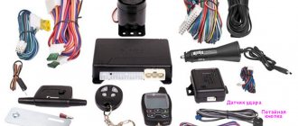
Car alarm sensors
If you install a car alarm on your car, the system will be enriched with several more car sensors, relays and switches.
Their types:
- Vehicle tilt sensor. Monitors the position of the body and turns on an alarm if the car begins to tilt. The sensor also reacts to any movement of the car, for example, made using a tow truck.
- Motion Sensor. It is located in the cabin and reacts to everything that happens inside. Sometimes it can be equipped with a microphone for more accurate tracking.
- Contact sensors. Installed on the doors, as well as on the trunk and hood. React to any hacking attempt.
- A device that measures the voltage level in the network. Gives an alarm when the current or voltage drops. Allows you to track any attempts to connect or disconnect components from the battery.
- Volume sensor. It reacts to the opening of the door (if for some reason the other sensors did not work or were turned off), as well as to any change in the volume of air that occurs, for example, when glass is broken.
Conclusion
Thus, it becomes clear how important various sensors are for cars. Without them, the operation of the engine and the car as a whole would be much more difficult, and fuel consumption, as well as the toxicity of exhaust gases, would greatly increase. As for car alarms and emergency call systems, their importance is generally difficult to underestimate. These devices help both save lives and preserve the car.
Article rating
Tags: featured, automotive sensors, sensors, sensors
- Related Posts
- Purpose, types and timing of air filter replacement
- What is a variator and how does it work?
- Car generator: purpose, design and principle of operation
Subscribe
0 Comment
Inline Feedbacks
View all comments
Camshaft position sensor
Similar to the DPKV, the camshaft position sensor (abbreviated DPRV) reads information about the angle of its position and transmits the corresponding information to the ECU. Based on the information received, the control unit makes a decision to open the fuel injectors at a certain point in time. Old injection engines (up to about 2005) did not have a camshaft position sensor installed. Because of this, fuel injection into the intake manifold on such engines was carried out in pairs-parallel mode, in which two injectors open simultaneously, which is characterized by excessive fuel consumption.
On engines on which DPRV is installed, so-called phased fuel injection is performed. That is, only one injector nozzle opens, where fuel should be supplied at the moment. As for the location of the sensor, on eight-valve engines it is mounted at the end of the cylinder head. On sixteen-valve power units, this sensor is also usually located on the cylinder head, near the first cylinder.
If the camshaft position sensor fails, the electronic control unit switches the engine to emergency mode, in which the injectors operate in pairs-parallel mode, opening simultaneously. This leads to excessive fuel consumption by 10...15%, in some cases the engine “troubles”. Typically, this generates an error signal in the ECU and activates the Check Engine light on the dashboard. Therefore, it is necessary to perform additional diagnostics using an electronic error scanner.
The DPRV sensor can be checked using a multimeter and/or an oscilloscope.
Clutch and brake sensors
Based on the signals from the clutch pedal position sensor and the brake light switch, the controller distinguishes between pressed and unpressed pedal positions. When the clutch pedal is pressed, the controller disables engine load regulation. Both sensors are located on the pedal assembly.
See "Replacing and Inspecting the Clutch Pedal Sensor" and "Replacing and Inspecting the Brake Pedal Sensor."
Some vehicle versions use an electronic throttle valve drive (E-gas). Let us remind you that in order to understand what errors are recorded in the ECU, you need to decipher them.
Keywords: Lada Granta sensors | Lada Kalina sensors | Lada Priora sensors | Lada Granta engine | Lada Kalina engine | Lada Priora engine | Lada Vesta sensors | Lada Largus sensors | 4x4 sensors | lada xray sensors | lada xray engine | Lada Vesta engine | Lada Largus engine | 4x4 engine | ECM Lada Vesta | ECM Lada XRAY | ECM Lada Largus | ECM Lada Granta | ECM Lada Kalina | ECM Lada Priora | ECM 4x4 | Niva sensors | Niva engine | esud niva | universal article
1 0 0 0 0 0
Share on social networks:
Anti-lock braking system sensor
As the name implies, this unit is key to the operation of the anti-lock braking system (abbreviated as ABS). On vehicles equipped with this system, there is one such sensor on each wheel. Their task is to record the speed of rotation of the wheel at a specific moment in time. The location method for cars may be different, but in any case the sensor will be located in close proximity to the wheel rim, in the area of the hub. Usually signal wires go to it, along which you can determine the exact location of the sensors on the front and rear wheels.
As a rule, the sensors themselves are quite reliable and rarely fail, except due to mechanical damage associated with the fact that they are installed in close proximity to the wheel and road. More often, the wiring going to/from them is damaged. It may fray or the insulation on the wires will be damaged. If the electronic control unit “sees” that incorrect information is coming from the sensor/sensors, then it activates the Check Engine warning light on the dashboard, and simply turns off the ABS system in emergency mode. Naturally, this leads to a decrease in driving safety.
Checking the ABS sensor is carried out in various ways - by measuring resistance, voltage or using an oscilloscope (the most advanced method). On newer cars, Hall effect sensors are installed as ABS sensors.
ABS sensor
Before purchasing a used car, special attention should be paid to the special ABS sensor. For testing, a conventional modern multimeter with full functionality is used. A more accurate check is performed at service stations using an oscilloscope.
We connect the device to the contacts, measure the resistance and compare it with the basic indicators, which are specified in the documentation for your car. During the measurement, it is necessary to shake the wires. If the multimeter readings change, this indicates an open circuit.
In addition to resistance, the ABS sensor is also checked for voltage. To do this, switch the multimeter mode from measuring resistance to measuring voltage. Next, we spin the car wheel up to 50 rpm and measure the voltage. The indicator should not exceed 2 V.
Hall Sensor
Sensors whose operation is based on the Hall effect (which is why they are called that) are used in electronic ignition systems. Their use provides two main advantages - the absence of a contact group (a problematic unit that can sometimes burn out), as well as providing a higher voltage on the spark plug (30 kV instead of 15 kV). However, similar sensors are also used in other systems of modern cars - brake, anti-lock braking, and tachometer operation. However, the principle of testing is almost the same and consists of measuring the resistance and/or voltage on the sensor with an electronic multimeter.
If the Hall sensor located in the electronic ignition system fails, the following external signs of this failure occur:
- problems with starting the engine, up to complete inability to start it;
- problems with the engine idling (interruptions appear, unstable engine speed);
- twitching of the car when driving in a mode where the engine has reached high speeds;
- The engine stalls while the car is moving.
A Hall sensor is a fairly simple and reliable device, but in some cases it can “lie,” that is, produce incorrect data. If, as a result of the test performed, it turns out that the sensor is completely or partially out of order, then it is unlikely to be repaired (and there is no point in doing so), so it is necessary to replace it. The sensor in the ignition system of a carburetor car is located in the distributor.
Checking the Hall sensor in the ignition system can be done in one of four ways.
Other important sensors
There are other sensors in the car that are extremely important. These include an outside temperature sensor and an incoming air temperature sensor. The devices operate on the same principle, they even have design similarities. The inlet air temperature sensor is installed in the intake tract.
Over time, new sensors appear in cars that make the life of the car owner easier and report important malfunctions in the car. However, the most important are the devices that affect the key functions of the car. Today it is impossible to imagine a modern car without these sensors.
Source
Oil pressure sensor
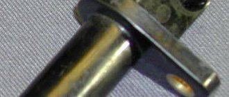
There are two types of oil pressure sensors (or oil pressure sensors for short) - mechanical (considered obsolete and installed, accordingly, on old cars) and electronic (modern, installed on most modern cars). Regardless of its type, the position of the oil pressure sensor is usually located in the area of the oil filter in the engine compartment.
Oil pressure sensors are fairly reliable devices (although the mechanical one fails more often, since its design has moving electrical contacts that fail over time), but malfunctions in their wiring occur (broken wires, damaged insulation). Signs of sensor failure will be problems with indicating pressure and/or oil level in the engine.
Please note that if problems arise in the operation of the oil pressure sensor, diagnostics must be performed as quickly as possible, since the low level of lubricating fluid in the engine crankcase is a critical indicator, and it must be kept at a normal value at all times!
Checking the oil pressure sensor is only possible when removing it from its seat. To check, the car enthusiast will need an electronic multimeter (it can be replaced by a control lamp) and an air compressor.
Powertrain control sensors
There are instruments related to engine management. These include sensors:
- position, speed;
- determining the amount of air;
- promoting blood pressure control;
- determination of temperature indicators;
- warning about the likelihood of detonation and monitoring the activity of the engine and fuel system.
This also includes the air sensor. The article talks about just a few possible sensors. Their number and quality are determined by the class to which the car belongs and its price. The more expensive and technologically advanced the car, the greater the number of sensors built into it.
Share:
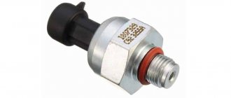
Fuel pressure sensor
The fuel pressure sensor is designed directly so that the ECU actually receives information about the value of this pressure. These devices are installed on both gasoline engines equipped with injectors and modern diesel engines with a Common Rail fuel system. These sensors are installed in the engine fuel rail. In both gasoline and diesel engines, the task of the fuel pressure sensor is the same, and is to ensure the pressure value within certain limits necessary for the normal functioning of the engine, ensuring its rated power, and normalizing noise during its operation. Some systems provide for the installation of two sensors - in high and low pressure systems.
Structurally, the sensor is a sensor element consisting of a metal membrane and strain gauges. The thicker the membrane, the greater the pressure the sensor is designed for. The task of strain gauges is to convert the mechanical bending of the membrane into an electrical signal. The output voltage value is about 0...80 mV.
If the pressure value goes beyond the specified limits (these values are stored in the memory of the electronic control unit), then the control valve in the fuel rail is activated in the system, and the pressure is adjusted accordingly. If the sensor fails, the ECU activates the Check Engine light on the dashboard and begins using standard (non-adjustable) fuel consumption values. This leads to the engine operating in a non-optimal mode, which is reflected in excessive fuel consumption and loss of engine power (dynamic characteristics of the machine).
You can read information about checking the fuel pressure regulator
Secondary sensors
Devices of secondary importance include:
- The oil pressure sensor calculates the indicator based on the degree of membrane deflection (present in Japanese cars) and is built into the cylinder system;
- the sensor that determines the level of fuel pressure is located in the fuel pump and, in cases of low pressure, sends a command to the booster pump;
- The anti-lock system has a built-in sensor for measuring the pressure exerted by the brake fluid;
- Some car models have built-in sensors under the seats that show the passenger's weight.
MAP sensor
In the classic version, the absolute air pressure (ABP) sensor is made of four resistors that have a variable resistance value and are connected by an electronic bridge. They are glued to a diaphragm, which either compresses or expands depending on what incoming air pressure is currently available in the intake manifold. The task of the DBP is to record changes in pressure in the intake manifold depending on changes in load and crankshaft speed, converting this information into an output electrical signal. This signal is traditionally sent to the electronic control unit, and based on this information, the ECU changes the duration of fuel supply to the combustion chambers, as well as the ignition timing.
As a rule, the air pressure sensor is located on the intake air tract (depending on the design of the particular vehicle). When it fails, problems begin in engine operation - idle speed “floats”, the car loses dynamic characteristics, and fuel consumption increases. If the sensor is damaged, it must be replaced with a new one.
How to check DBP
If the absolute air pressure sensor in the intake manifold malfunctions, the car’s engine will not operate stably and its power will decrease. You can check the functionality of the DBP sensor with a multimeter and a syringe. But first you need to clean it Read more
Classification features of sensors for cars
The number of car assistants in the car market today has increased many times over. All of them are different in their characteristics, application features and intended purpose. According to the requirements and operating conditions, sensors are divided into several classes:
- The first class is aimed at monitoring and diagnostic examination of brakes and steering. Responsible for the safety of passengers.
- The second class of devices is aimed at monitoring the integrity of the transmission, engine, tires and suspension.
- The third class is aimed at providing protective functions for the car and is responsible for the comfort of movement.
Thanks to modern developments in electronics, tracking devices are made of high-tech materials and are highly reliable. Small dimensions allow you to simultaneously use several computer devices in one car, which are capable of storing and systematizing information, correcting it and eliminating possible errors.
Types of sensors for vehicles:
- Fiber optic devices. Sensitive to dirt and quickly fail. They have low susceptibility to electromagnetic interference. They do not tolerate pressure. Sensors of this type are not applicable to all cars, since their operation requires special connectors and taps. In internal sensors, the signal is generated inside the optical fibers, and in external sensors, the signal is generated outside it.
- Integrated sensors endowed with intelligence. They reduce the load on the control unit, form flexible communication lines, make it possible to simultaneously use several built-in devices in one car, and process signals even with low intensity.
Phase sensor
The operation of the phase sensor is based on the Hall effect mentioned above. Its task is to fix the so-called top dead center of compression of the piston of the first cylinder. The relevant information is transmitted to the ECU, and based on it, phased fuel injection is carried out into the remaining cylinders in accordance with the operating order of the engine cylinders. As a rule, the installation location for the phase sensor is the rear of the cylinder head.
If the phase sensor fails, a misphasing of fuel injection into the cylinders occurs, that is, the engine switches to unphased fuel injection mode. The electronic control unit then activates the Check Engine warning light on the dashboard. At the same time, the engine begins to work unstably, up to a complete stop, the dynamics of the car decrease in different driving modes, the engine “troubles”. In some cases, on the contrary, increased fuel consumption is observed. Replacing the sensor is not difficult. Usually all you need to do is use a wrench.
You can see partial information on how the phase sensor is checked
Intake air temperature sensor
The sensor is abbreviated as DTVV or in the English abbreviation IAT. It is necessary to ensure that the air-fuel mixture has the optimal composition for engine operation. As a rule, the intake air temperature sensor is installed on the air filter housing or behind it, that is, in places where air is directly drawn into the engine. In some cases it may be part of the mass air flow sensor. Failure of this element threatens unstable engine operation, “floating” idle speed (they will be either too high or too low), loss of vehicle dynamics and power. Also, if the unit is faulty, there will be problems with starting the engine, as well as significant excessive fuel consumption, especially in severe frosts.
A sensor malfunction can be caused by damage to its electrical contacts, failure of its signal wiring, low voltage in the automotive electrical network, a short circuit inside the sensor, or dirty contacts. To be fair, it should be noted that this sensor, unlike many others, can be restored to its functionality, that is, without replacement. Sometimes basic cleaning helps (you need to do it carefully).
The operation of the intake air temperature sensor is checked using an electronic multimeter.
Intake system channel length control valve
AVTOVAZ began installing an intake manifold with variable geometry starting with the VAZ-21127 engine. This design allows for maximum torque at low speeds and maximum power at high speeds. The length of the intake manifold is adjusted (switching from one length to another) using a valve that is part of the engine management system.
See how to replace and test the sensor.
Checking the sensors
In most cases, the verification process is simple and does not take much time. Before performing the test, it is recommended to scan the memory of the electronic control unit for errors using a special scanner (for example, the popular ELM 327 device or its equivalent). This will make it easier to check both a specific sensor and a malfunction of the vehicle as a whole.
Sometimes situations arise when the location of a particular sensor is unknown. In this case, it is better to seek help from the manual. Also on specialized websites there is information about the position of sensors on specific car models.
Conclusion
Before checking a particular sensor, you need to make sure that the signs of failure indicate the failure of a particular sensor. If you have doubts about this, it is better to seek help from a car service center. Direct testing in most cases is performed using an electronic multimeter capable of measuring electrical resistance and DC voltage in the range of up to 12 Volts. Therefore, purchase such a device if you don’t already have one. It is not necessary to take expensive samples; a device from the middle price category is quite sufficient (you should not buy a very cheap one either, since it may show incorrect data). Well, to dismantle the sensors, you need to have regular plumbing tools on hand - wrenches, screwdrivers, and so on.
Video: do-it-yourself installation of a remote oil pressure meter
Filmed by the “Auto Repair and Tuning” channel.
Do you have any questions? Specialists and readers of the AUTODVIG website will help you ask a question
Was this article helpful?
Thank you for your opinion!
The article was useful. Please share the information with your friends.
Yes (100.00%)
No
X
Please write what is wrong and leave recommendations on the article
Cancel reply
Rate this article: ( 4 votes, average: 5.00 out of 5)
Discuss the article: