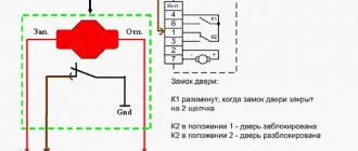
How to turn a “minus” into a “plus” and vice versa? How to hook up to an electric drive? How to open the trunk with the alarm key fob? How to block the engine from starting? There is an answer to all these questions: using a relay.
Knowing how a relay works, you can implement various connection schemes to the car's electrical wiring.
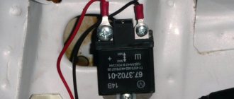
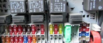
Usually the relay has 5 contacts (there are also 4-pin and 7-pin, etc.). If you look at the relay carefully, you will see that all contacts are signed. Each contact has its own designation. 30, 85, 86, 87 and 87A. The figure shows where and what contact is.
Pins 85 and 86 are the coil. Contact 30 is a common contact, contact 87A is a normally closed contact, contact 87 is a normally open contact.
At rest, i.e., when there is no power to the coil, contact 30 is closed with contact 87A. When power is simultaneously supplied to contacts 85 and 86 (one contact is “plus” and the other is “minus”, no matter where it is), the coil is “excited”, that is, it is triggered. Then contact 30 is disconnected from contact 87A and connected to contact 87. That’s the whole principle of operation. It seems to be nothing complicated.
A relay often comes to the rescue when installing additional equipment. Let's look at the simplest examples of using relays.
Engine lock
The blocked circuit can be anything, as long as the car does not start if the circuit is broken (starter, ignition, fuel pump, injector power, etc.).
We connect one coil power contact (let it be 85) to the alarm wire, on which a “minus” appears when arming. We apply +12 Volts to the other contact of the coil (let it be 86) when the ignition is turned on. Contacts 30 and 87A are connected to the break in the blocked circuit. Now, if you try to start the car with the security switched on, contact 30 will open with contact 87A and will not allow the engine to start.
This scheme is used if you have a “minus” from the alarm to blocking when arming. If you have a “minus” from the alarm to blocking when disarming, then instead of contact 87A we use contact 87, i.e. The open circuit will now be on pins 87 and 30. With this connection, the relay will always be in working condition (open) when the engine is running.
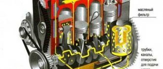
General description of the design
- Perceiver. This is the primary element that perceives the controlled quantity and converts it into another physical quantity.
- Intermediate. Compares the received value with the specified parameter. If this value is higher or lower than the specified parameter, then the primary effect is transmitted to the actuator.
- Executive. This element transmits the action to circuits controlled by relays. As a result of such an impact, the following may occur: opening or connecting the controlled circuit, switching current parameters.
The design and operating principle of the primary element depend on what purpose the relay has and what physical quantity (current, voltage, light, heat, etc.) it is set to.
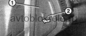
Opening the trunk using the car alarm key fob
If your car has an electric trunk drive, you can connect to it with a car alarm to open it using the alarm key fob. If the alarm outputs a low-current signal to open the trunk (and most often this is the case), then we use this circuit.
First of all, we find the wire to the trunk drive, where +12 Volt appears when the trunk is opened. Let's cut this wire. We hook up the end of the cut wire that goes to the drive to pin 30. We hook up the other end of the wire to pin 87A. We connect the alarm output to contact 86. We connect contacts 87 and 85 to +12 Volts.
Design
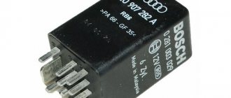
The radio relay is made in a small block; the body of the device is usually made of plastic. Structurally, the block itself includes an electronic circuit, as well as a relay chip. These components are used to monitor specific controllers installed in the machine.
You can find several types of engine blockers on sale. Let's look at the features of each of them in more detail.
Regular
Conventional analog devices can be made in several variations. The first option is considered the simplest to implement; it is installed in a microprocessor car alarm module. The broken electrical circuit is connected to the control module. The main advantage of such blockers is ease of installation and high fault tolerance. But these devices cannot be classified as anti-theft devices. If the criminal gets to the microprocessor unit, he can quickly restore the broken circuit.
The advantages of such devices include fault tolerance. Compared to the first option, the theft resistance of remote locks is higher, but it also cannot be classified as a full-fledged anti-theft means. If a criminal gains access to a microprocessor device, he can quickly apply voltage to the control power line. This will allow you to restore the broken chain and start the engine.
Analog engine blocking relays are not recommended for use, since they cannot provide effective protection against theft.
The Nördlich Bär channel showed the operating principle of a simple power unit lock.
Digital
Digital devices are divided into several types:
According to technical parameters, digital devices are divided among themselves:
Wireless
Such blockers cannot be forced to open or close contacts by applying voltage. An electronic board is installed in the device body, which is controlled by an electromechanical component. The transmission of commands is carried out in encrypted form, so it is almost impossible to detect the signal and intercept it.
The main advantage of wireless blockers is that a consumer can simultaneously install several dozen such devices on a car engine, it all depends on financial capabilities.
Single wire
Single-wire devices are not susceptible to interference. To connect such blockers, not a standard electrical circuit is used, but a separate single-wire line, through which packet data is transmitted. This type of connection allows you to provide reliable protection from interference, increased loads, and also increase the power of the transmitted pulse. The wiring does not transmit code signals, so if a criminal wants to use a bug for hacking, he will have to find the appropriate cable.
The disadvantages of the devices include the complexity of installation compared to wireless blockers. To prevent intruders from turning off the relay, it can be moved to the engine compartment and an additional lock can be installed on the hood. Single-wire relays are not so in demand among consumers. The fact is that it is almost impossible to implement an invisibility lock with a wire.
Legislation
Before practicing installing DRLs, I would like to dwell a little on the legal standards for installing DRLs, as well as the rules of their operation.
The very first and basic rule is that unauthorized installation of additional light signals on a car is prohibited. Yes, you are right, you do not have the right to install DRLs on your car if it was not equipped with them by the manufacturer. This will be considered as making changes to the design of the vehicle. For every change to a vehicle's design, a certificate must be obtained, which in itself is neither quick nor cheap. Otherwise, traffic police officers will issue you a fine, or even take your car to the impound lot.
How so? My neighbor installed DRLs on the Oka and drives calmly! - you ask. He is simply lucky to have loyal traffic police officers who do not pay attention to his DRL - I will answer you.
Once again, unauthorized installation of additional light signals on a car is prohibited if it was not equipped with them by the manufacturer. Therefore, you make any changes to the design of the vehicle at your own peril and risk. It’s a completely different matter if your car’s equipment does not include DRLs, but the more expensive trim levels of your model do have DRLs. In this case, you have the right to install DRL without any approval from the certifying authorities.
The first rule for installing DRLs concerns their location on the car body (see picture). If we briefly describe this figure, we get the following:
- DRLs should be installed at a height of 250 to 1500 mm;
- The distance between adjacent edges of the DRLs must be at least 600 mm;
- The distance from the outer side surface of the vehicle to the nearby edge of the DRL should be no more than 400 mm.
Now let’s briefly go through the rules of operation and use of DRLs:
- DRLs should only be used during daylight hours;
- It is prohibited to use DRLs in conjunction with side lights, low and high beam headlights, as well as fog lights.
Everything that is not prohibited is permitted. It's that simple. Separately, I would like to dwell on an important point, it concerns the use of DRLs in conjunction with high beam headlights. The rule goes something like this: When the high beam signal is briefly signaled, with the side lights and low beam headlights turned off, the DRLs should not turn off. Let me break it down: you are driving with your headlights and side lights turned off, your DRLs are on, when you signal with your high beams to an oncoming car that you are approaching a traffic police post, your DRLs should not turn off.
Just? I also think that there is nothing complicated here. Knowing the legislation and rules for using DRLs, we are ready to move on to the practice of connecting them. Let's start with the simple and incorrect and end with the complex and correct. Go!
What types of sensors are there?
Depending on the scope of application, RKU can be equipped with various types of sensors:
Electrode. This type is considered the most reliable and works by touching the liquid in the container with the electrodes. In the container, the shortest electrode plays the role of a kind of level, in contact with which the liquid stops flowing into the reservoir. The electrode water level sensor, which is long, is responsible for starting the flow of liquid into the tank or other container.
Float This type of sensor works on the following principle: between two supports on the cable there is a special rocker arm, which rotates when limit levels occur. Such a liquid level controller is capable of turning the pump on and off, but it is used in conditions of interaction with non-aggressive liquids.
Capacitive sensor or, as it is also commonly called, a parametric type water level meter. Such sensors are capable of transforming the measured value into a change in capacitance.
Depending on which sensor is installed in the water level regulator used, the circuit of the relay itself will depend.
DRL connection diagram without relay
This is the simplest DRL connection diagram, but also the most incorrect. I'll describe it a little. With this connection scheme, you supply voltage to the DRLs from the main power circuit of the car. The main power circuit is activated when the key is turned in the ignition switch. Obviously, your DRLs will always work as long as the key is turned in the ignition, no matter what lighting you use. You have no way to turn off the DRLs until you remove the key from the ignition.
As you already know, the use of DRLs in conjunction with other lighting devices is prohibited. I do not recommend connecting DRLs using this scheme.
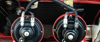
Design and principle of operation of an electromagnetic-thermal turn relay
Relays of this type do not have a very complicated design. It is based on an electromagnetic relay of a traditional design - a cylindrical core with a winding of thin copper wire. At the top of the core there are two contact groups, and on the sides there are flexible metal anchors (or, as they are called, anchors). One contact group is designed to close the circuit of the turn signal indicator lamp located on the dashboard. And the second contact group directly closes the circuits of the direction indicator lamps, and it is its design features that ensure the blinking of the turn signals.
The armature of the contact group of the turn signal lamps is pulled away from the contact located on the core using a thin nichrome string, so in the normal position the turn signal circuit is open. The opposite end of the string is fixed on a platform made of insulating material, which serves as the basis for installing the core. The nichrome string is connected through a resistor to the turn signal switch circuit, so current flows through it during operation of the relay.
This entire structure is placed in a cylindrical metal case; the bottom of the case is a platform made of insulating material with a relay. At the bottom of the platform there are contacts with the help of which the breaker relay is connected to the turn signal circuit.
The operation of an electromagnetic-thermal relay is quite simple and boils down to the following. When the turn signal is turned on, a circuit is closed that includes the turn signal lamps, a resistor, a relay winding and a nichrome string. Due to the resistance of the resistor, the voltage supplied to the lamps is low, so their filaments burn at full heat. Nichrome, as is known, has a high resistivity and heats up greatly when current flows - thanks to this heating, the nichrome string increases its length, and the armature pulled by it, under the influence of the attraction of the core, straightens and at some point closes the contact group. As a result, current begins to flow bypassing the resistor and the nichrome string, and the turn signal lamps light up in full force.
However, stopping the heating of the string leads to its cooling and shortening, and the armature is again pulled away from the core, opening the contacts - the turn signal lamps go out, and the cycle repeats again. The heating and cooling of the nichrome string occurs quickly, so the lamps blink at a frequency ranging from 60 to 120 times per minute.
The current position of the contact group of the direction indicator lamps (let's call it the first) is associated with the work of the contact group of the signal lamp (let's call it the second). When the contacts of the first group are open, current flows through the winding, but it is not enough to attract the armature of the second group, so the signal lamp does not light up. When the string is pulled and the first contact group is closed, the current flowing through the winding increases sharply, and it is already sufficient to attract the armature of the second contact group. As a result, simultaneously with the blinking of the direction indicators, the warning light on the dashboard also blinks.
Characteristic clicks during operation of the direction indicators occur due to the impact of the anchors on the contacts when they are closed and opened. Clicking is a characteristic feature of electromagnetic relays, and it comes in very handy in breakers.
The electromagnetic-thermal relay has a simple design, and this is its main advantage. But this type of relay has many more disadvantages: over time, the string is stretched, as a result of which the relay stops functioning normally, during operation the relay heats up, which changes its characteristics, and if one of the turn signal lamps burns out, the blinking frequency of the second lamp decreases significantly, and In some cases, the lamp stops lighting up altogether.
Today, electromagnetic-thermal relay-interrupters have been replaced by more modern and advanced electronic relays.
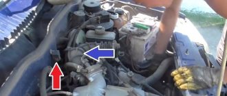
DRL connection diagram via 4-pin relay
To connect the DRL according to this scheme, you, as in the previous case, will need a 4-pin relay. Moreover, the connection diagram is absolutely identical to the previous case, only instead of the control signal from the oil pressure sensor, we will use a button in the car interior. Your DRLs will only turn on when you press a button in the cabin.
You can add a little automation to this scheme. In order for the DRLs to go off when the engine is stopped, you can send a signal to the button from the fuel pump, or from the same oil pressure sensor. This scheme already has the right to life, because you can control the DRL operation depending on your driving conditions.
The only downside is that you need to manually turn off the DRLs (press a button in the cabin) when you turn on the low beam headlights, and also manually turn on the DRLs when driving during daylight hours.
How to connect and configure?
You can install and connect the blocking device yourself.
Auto-latching relay
Let's look at an example of connecting a signal blocker Starline B62 Dialog. On the main board of the microprocessor unit there is a blocking device with a group of switching contact elements. On Starline B62 this output is marked as X1. The maximum current generated is 15 amperes.
The connection procedure is performed as follows:
- Before installation, the specific operating mode of the relay is programmed. Depending on the alarm model, the setup process may differ. In the case of the B62 Dialog system, programmable option 10 is used for configuration. Initially, the device is configured for a normally closed interlock.
- Decide on the installation location. The installation must be performed in one of the standard electrical blocking circuits of the power unit. For example, you can install the device in the gap of the fuel pump or injectors.
- Two of the three contact elements of the built-in blocker are connected to the created gap. Blue and white-blue wires are used for connection. These electrical circuits are included in the “signaling” package.
- If the connection is made into a power line break with an inductive load, the magnitude of the current must be taken into account. The maximum switching parameter may be greater than the maximum current with which the blocker operates. This may cause it to break.
Remote latching relay
We will look at an example of a safe connection of a digital relay using the Starline P2 model as an example. A detailed device connection diagram is presented in the technical manual.
Before installing and connecting the blocking relay, you need to understand one of the operating modes of the device. It is determined by the consumer based on the state of the electrical circuit loop that comes out of the blocker board. If the loop is intact, then the closed mode is activated; if the loop is open, the normally open mode is activated.
Connection and installation:
- The installation procedure is similar. The device crashes into one of the electrical circuits of the car - the fuel pump, injectors or starter device.
- To connect, you need to go to the settings menu for the main “signaling” options. Select the blocker operation mode - 3 or 4 options 10, detailed information about the functions can be found in the service manual. Once selected, disable the option settings menu.
- Connect the black cable marked MAC to the car body.
- Turn off the ignition and click on the Valet service key seven times.
- Turn the key in the lock to turn on the ignition. The “signaling” siren will emit seven beeps, this indicates entering the blocker setup mode.
- Within five seconds, connect the black cable marked ZAZH to the electrical line of the ignition system. If the device is paired, the siren speaker will play one long beep.
- To leave the binding mode, turn off the ignition system or wait five seconds and the “signal” will automatically leave the menu. If you plan to use several relays, then install and connect the second device in the same way. When the second relay is successfully linked, the siren will emit two extended beeps.
If, in the event of an attempt to bind a blocker, the siren plays three extended signals, this indicates that the device has already been entered into the memory of the microprocessor unit.
A blocker that has been stored in memory cannot be linked to another communicator; to do this, you will have to reset all settings.
Andrey Kondrashov spoke about the independent implementation of car engine blocking.
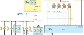
Connection diagram for DRL via 5-pin relay
This scheme is the most correct and automated; I recommend connecting the DRLs according to this scheme. This circuit uses a 5-pin relay. Let's talk a little about the operating principle of a 5-pin relay. The 5-pin relay has 2 power outputs. In the normal state, the first of the power terminals is closed, the second is open. After applying a control signal to the relay, the first output will become open and the second will become closed. This seems complicated, but let's look at an example and everything will become clear.
- Contacts 85 and 86 are control contacts. Depending on whether there is voltage on them or not, contacts 87 or 87A close;
- Contact 30 – power supply contact of the relay. It is to this that voltage must be supplied to power consumers;
- Contacts 87 and 87A – contacts for connecting consumers.
Let me give you an example. There is no voltage on contacts 85 and 86; power through the relay goes to the consumer at contact 87A. There is voltage on pins 85 and 86, the relay switches power to the consumer on pin 87.
- We supply power to the DRLs and headlights through pin 30. For greater automation, take power from the main circuit of the car, which turns on when the ignition is turned on;
- We connect DRLs to contact 87A, which will always be on;
- We connect the headlights to pin 87, which will turn on only when the DRLs are turned off;
- To contacts 85 or 86 (it doesn’t matter), we apply a control signal from the headlights button in the cabin;
- We connect the remaining contact 85 or 86 to the car body.
With this connection, either the DRLs or the headlights may work. When the car is turned off, both the DRLs and headlights are turned off.
- Price: $1.66
- Go to the store
In today's review, I will share with you my impressions of a 5-pin automotive relay purchased on eBay, and also show one of the possible options for its use.
The relay was ordered almost simultaneously with the DRL kit that I talked about a few days ago. For what? Because when using a standard connection, when turning on the side lights or low/high beams, the DRLs still continued to light up. I didn’t find anything good in this, and therefore I began to think about automating their shutdown when turning on the headlights or low beam. The simplest and most logical option seemed to me to be using a relay.
By the way, this is one of the few purchases that I went to the local auto parts store before making. Imagine my surprise when I saw the price in the VAZ store: relay - 5 rubles (about $2.5), a block for it - 2.5 rubles ($1). Total, $3.5 per set offline with us without waiting, versus $1.66 with them. The choice is obvious