During the operation of a car, problems with the battery and generator often arise. Often, the battery may fail due to insufficient charge. This problem is relevant both for many foreign cars, especially with mileage, and for various domestic cars (VAZ, GAZ, ZAZ, etc.).
For normal operation of a car battery, it is necessary that the generator charges the battery while the engine is running, and neither undercharging nor overcharging of the battery is allowed. Next, we will look at problems with battery charging using the example of a VAZ 2106, the charging relay on this car model, and also how to check the VAZ regulator relay yourself.
Electric relay device
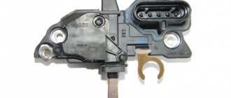
An automobile charging relay, a photo of which can be found on our Internet portal, contains the following elements:
- Electromagnetic device - consists of a coil with a metal core that exhibits magnetic properties, and a wire of a certain cross-section that plays the role of a winding.
- An anchor element is a product made from a special plate that directs the contacts to the desired action, depending on the impulse received from an electromagnetic type coil.
- Position switch - combines the functions of switching, opening and closing contacts.
When voltage is applied through the electromagnetic winding of the coil, an electric field is created that attracts the armature element to the core, and the pusher, under the influence of the coil current, stirs the armature element, thereby switching the contacts of the “six” charging relay, the price of which is quite reasonable for Russian motorists. The correct connection of the charging relay can be seen in the image below
There are 2 main types of charging regulator relays used on “sixes”. These include:
- Automotive relay-regulator charging VAZ 2106 non-contact type, having the nomenclature number 121.3702. This is a relatively new electronic device used to complete the power equipment of the Six. The main advantage of this device is its complete autoregulation.
- The product under the symbol PP-380 with the same functions is installed on the “six” from the beginning of its release from the assembly line. The part is currently discontinued.
These charging relays are interchangeable, and, which is very convenient, without subsequent modifications and adjustments to the VAZ 2106 charging circuit, which is presented below
The VAZ 2106 charging circuit diagram includes a charging lamp relay (RS-702), which serves to receive signals from an indicator lamp on the instrument panel, which shows whether the charge current is flowing to the windings of the generator device and indicates its functionality. This charging lamp relay is located on the right fender liner in the engine compartment.
To check the functionality of the charging relay regulator of the VAZ 2106, you need to turn on the ignition, start the engine and achieve the required number of revolutions (2500-3000 rpm) of the power plant. Next, you should turn off all automotive electrical consumers (except for the ignition), and measure the potential difference at the output contacts of the product. The voltage at the ends should be 14.2 Volts.
If, when the charging relay is connected correctly, a problem is observed with its functionality, then this device should be repaired. To do this, you must have certain skills in electrical engineering and the ability to use an ampere-voltmeter and other measuring instruments and, possibly, a soldering iron. Otherwise, it is necessary to replace this element of the vehicle's electrical system, which can be purchased at a specialized store of automotive spare parts and components. Such a charging relay has a relatively low price, at least quite comparable with other components of the vehicle’s power supply system.
Mechanical problems
Therefore, regardless of whether your car has a carburetor or an injector, it is better not to joke with the generator, but if malfunctions are detected, respond quickly to them.
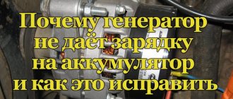
If the generator stops charging, there is nothing good about it. It is necessary to immediately begin searching for the cause of such a malfunction. Otherwise, all your electrical equipment will be without power, and the battery will soon run out completely.
If the generator works well, then the battery will not need additional charging with special devices for many months, sometimes even years. The battery will consistently retain at least 60% charge. Thus, the batteries are constantly replenishing their charge reserve through the operation of the generator.
Replacing the battery charging indicator relay
Work on replacing the VAZ 2106 charging lamp relay should be carried out in the following sequence:
- We unscrew the 2 fasteners of the charging lamp relay and remove the product from the installed studs.
- We mark the supply wiring with a marker or felt-tip pen to control the correctness of the reverse connection of the updated product. If the relay is incorrectly connected to the vehicle's power supply network, it stops functioning, which will create an emergency situation due to a sharp increase in the potential difference at the output contacts of the generator device.
- We disconnect the wire circuit, replace the relay with a working product and carry out the reverse installation.
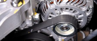
When testing the charging lamp relay, it is strictly forbidden to make a short circuit between the output elements of the circuit, because this will cause defects in the current rectifier unit. Before testing the charge regulator relay, you must ensure that the alternator belt tension is optimal. Other energy resources should not be connected to the electrical circuit of the generator excitation winding, because the voltage drop on the VAZ 2106 charging relay under study may exceed the optimal values.
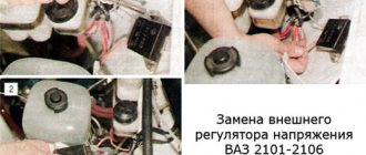
On the “classic” you can find 2 types of voltage regulator relays: built into the generator and external. The difference lies in the model of the generator that is installed on the car.
On older Zhiguli models (VAZ 2101, 2102, 2103, 2106, 2121 with carburetor engines) a G-221 generator is installed, and the external voltage regulator is a small “box”, which is secured with two nuts on the left mudguard of the body. It is precisely the replacement of such a regulator that will be discussed in this article.
On later VAZ models (2104, 2105 and 2107) there is a G-222 generator, and the voltage regulator is already built into the generator housing and is a small black “tablet”.
Understanding the reasons for charging problems on the VAZ 2106
Where is the relay located on the VAZ 21099 starter?
To check the electrical connection of a car, you need a simple multimeter or voltmeter. The most common reasons for low charging voltage are:
- The generator belt tension is too weak or too worn;
- generator malfunction (worn brushes, faulty diode bridge, broken or burnt stator or armature coils);
- voltage regulator malfunction;
- shaving in charging area.
The most common cause of charging failure is a malfunction of the voltage relay. In order to verify its usefulness, it will be enough to get rid of the grievances, unite with each other, start the engine. For the sake of understanding that all other elements of the lance are attached, the voltage in the lance is close to 17 V or more. If the voltage does not increase, then it is necessary to check the presence of +12 V at the terminal connected to pin 15 of the relay regulator. If necessary, check the lance, which confirms the lance and the very integrity of this lance.
If the food is on this terminal, it is necessary to check the connection in the generator wake-up circuit. Connect the test lamp between the +12 V battery and the wire that connects to connection 67 of the voltage regulator relay. In this way, you can check the voltage relay-generator circuit, as well as check the generator brushes and windings of its armature. If there is no voltage at the lamp pins, worry about a malfunction of the direct bridge.
Next, check the serviceability of the conductor from the generator to the relay regulator. For such a check, it is necessary to disconnect the terminal from the generator and connect it to -12 V. For the control lamp, talk about faulty brushes or broken armature windings. If a malfunction of the generator is suspected, it should be removed from the vehicle and rotated outside of disassembly. Next, check the integrity of the diode in the diode bridge of the generator, check the continuity of the stator and armature coils for damage or burnout. Faulty elements must be repaired or replaced.
The VAZ 2106 battery charging circuit transmits a constant voltage of 13.5 to 14.3 V, regardless of engine speed. However, outbursts occur when at mid-speed the engine voltage noticeably “sags” when the additional voltage is turned on. If such a phenomenon occurs, it is necessary to check the tension of the generator belt and adjust it. Weak contact at the battery terminals can also lead to this effect.
Since the voltage at the battery terminals is higher than the indicated values, it is necessary to check all contacts, starting from the positive connection of the battery to the voltage regulator relay. If all contacts are normal, then the relay regulator prompts replacement.
Keeping a close eye on your car's electrical system, the contacts and terminals of the battery, regularly checking the belt tension and the level of the electrolyte in the battery will allow your car's engine to run smoothly and without problems, and you will be safe There are a lot of malfunctions in the dosage.
Removing and installing the voltage regulator
Replacing the external voltage regulator VAZ 2101-2106
1) Using the “8” socket, unscrew the two nuts and remove the regulator.
2) Disconnect the two wires.
3) Attach the new regulator to the mudguard and connect the wires: orange to terminal “15”, and gray to terminal “67”.
Voltage regulator relay connection diagram
ATTENTION! Before starting the engine, make sure that the contact between the voltage regulator housing and the vehicle ground is reliable, and that the wires to terminals “15” and “67” are connected correctly.
How to test a generator with a multimeter
The diode bridge of the generator can be checked with a multimeter, but you can also use the stand that was used to check the regulator.
But before that, first of all, without removing the rectifier bridge from the generator, connect the red wire of the tester to terminal 30 of the generator, and the black wire to the housing. Set the tester operating mode to dial (diode icon). If it is not there, then set it to 1-2 kOhm. The multimeter should show infinity. If the readings are different, the diode bridge is faulty.
Then check the current rectifiers for breakdown. Leave the positive (red) probe on terminal 30, touch the negative one to the bridge mounting bolts one by one. The multimeter display should show infinity in all cases; any others mean a breakdown.
Next, connect the positive probe to the axle mounting bolts, and the negative probe to the generator housing. In this case, the tester should also output infinity.
But in practice, such verification is most often not enough. In most cases, it is necessary to ring the generator in more detail.
Careful testing
To do this, unscrew the fastening bolts of the rectifier unit, disconnect the copper wires of the stator winding and remove the diode bridge from the generator. Now you can test each semiconductor individually. Before checking, it is advisable to rinse the stabilizer with running water using a medium-hard brush, and then dry thoroughly. For quick drying, a hair dryer is quite suitable.
Attach one of the tester probes to the diode plate, connect the second to the central terminal of each diode fixed to this plate. Then swap the probes. In one case, the multimeter should show infinity, in the other - a nominal resistance of approximately 570-590 Ohms. Rectifiers are considered faulty if:
- In the first and second measurements (when the polarity was changed), the multimeter readings are the same;
- Diode resistance is greater or less than nominal values.
Perform the same actions with the second plate of the diode bridge. If a fault is detected in one or more diodes, it will be easier to replace the entire rectifier unit. True, there are craftsmen who replace failed diodes individually, but such work requires a certain skill and dexterity.
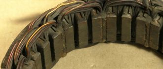
Checking the armature and stator windings
Further inspection requires completely disassembling the generator. First of all, visually check the anchor. Brush rings should not show any blackening, chipping or wear on the treadmills. Blackening and slight wear can be smoothed out with zero-grade emery cloth. Rings with deep grooves must be replaced or, if the thickness of the rings allows, turned on a lathe.
The armature winding should not clearly smell like burning. The color of the winding must be uniform and free of damage and breaks. To check the armature winding for a break, you will need a multimeter. Set the operating mode to continuity testing or resistance measurement and connect the probes to the brush rings. The winding resistance should be within 3-5 Ohms. Then leave one probe on the ring, connect the other to the body. The multimeter display should show infinity.
The generator stator is diagnosed after removal from the housing. First of all, carry out a visual inspection. There should be no visible damage to the wire or its insulation. Then connect the tester wire to the stator housing. With the second wire, touch the terminals one by one. There are only three of them. The tester must be in dialing mode. If the display shows infinity, this indicates that the stator is working properly.
Further testing consists of diagnosing the windings. The resistance of all three windings must be the same.
Before assembling the generator, you need to check and, if necessary, replace the bearings. When turning, they should not jam or make a creaking sound. This means that they are very worn out and will soon fail. Therefore, it is better to replace them immediately.
Types of relay regulators VAZ
In recent years, a relay regulator with the designation 121.3702 was installed, which worked in symbiosis with the G-221 alternating current generator. But such a perfect device, which does not require any adjustments or additional maintenance, began to be used in the 90s. Initially, cars came off the assembly line with a PP-380 vibration regulator. So it needed adjustments, settings, and even maintenance. When working with the PP-380 regulator, you need to follow simple rules.
- Do not under any circumstances confuse the wires marked “67” and “15”. If this happens, the relay regulator will not function; its contacts located on top will be short-circuited. The result is a sharp increase in voltage at the output terminal of the generator, boiling of the battery, failure of all electricity consumers and the VAZ 2106 voltage regulator itself.
- It is not allowed to connect capacitors to the circuit of plug “67” to counteract radio interference. The contacts end up working incorrectly and as a result they are destroyed.
- It is prohibited to include any electrical energy consumers in the excitation winding circuit. Otherwise, the output voltage increases several times.
- The plugs numbered “67” and “15” cannot be connected to each other, since the output voltage increases significantly and the probability of failure of the semiconductor rectifier is very high.
- It is not recommended to remove the cover from the regulator, because dust and moisture can get into it, the contacts will begin to burn and become dirty, which will lead to improper operation of the mechanism. Installation of gaskets made from scrap materials is prohibited.
- Do not hit the regulator body, keep it clean.
- The electrical connections between the ground of the VAZ 2106 car and the device body must be reliable, with minimal resistance. If the connection is weak, then the probability of voltage increase is very high.
The requirements for the old type of VAZ 2106 relay-regulators are listed, but for the non-contact one, all points can be applied except 5. It will not be possible to remove the cover from the non-contact voltage regulator, since it does not have one. Therefore, if the entire unit fails, it will need to be completely replaced; repair is impossible.
Let's sum it up
As you can see, the generator relay for a VAZ or any other car is an important and responsible device. Moreover, any malfunctions in its operation will lead to the fact that the car’s battery will not be charged properly. In this case, both low and high battery charge will quickly damage the battery.
We also recommend reading the article about what to do if the electrolyte in the battery freezes. From this article you will learn why the electrolyte in the battery freezes, as well as what to do if the car battery freezes.
If the signs of a generator regulator failure discussed above appear to a greater or lesser extent, it is necessary to check the regulator using one of the methods discussed above. Finally, we note that it is not difficult to replace the generator voltage regulator on a VAZ, but some nuances must be taken into account separately.
What is contactless ignition and its advantages
Another interesting option for tuning classic models is installing a contactless ignition type. Definitely, the car only benefits from such an innovation - the engine runs smoother, dips disappear when accelerating the car, and it is much easier to start the engine in cold weather. In addition, there are savings associated with fuel consumption.
The wiring diagram on the VAZ 2106 in this case is almost identical: the main differences are the presence of a pulse sensor and the absence of a distributor. While the engine is running, the sensor creates pulses that enter the transistor switch.
Already with its help, other impulses are generated, characteristic of the primary winding on the coil. With interruption, the secondary winding produces high voltage current. From the distributor contact, current is supplied to the spark plugs in the required sequence.
So, you purchase a non-contact ignition package for a VAZ “classic”, which must match the characteristics of the car’s engine. Next, we will need a wiring diagram for the VAZ 2106.
The following spare parts should be included in the configuration of such an ignition:
- switching unit;
- coil;
- high voltage wiring kit;
- spark plugs - DVRM;
- connecting wires.
Stages of work
To successfully replace the ignition with a contactless one, it is important to adhere to the principles of following the correct work technology. Remove the negative terminal from your battery
Any type of electrical repair should always begin with this action.
This is where the wiring for the VAZ 2106 will come to the rescue:
- We disconnect the wires and the main high-voltage wire from the ignition coil.
- Remove the distributor cover.
Be careful not to damage other wires
- The slider should be placed so as not to disturb its necessary settings.
- The mark on the block is placed where there are slots at the bottom of the distributor body.
- Unscrew the nut and take out the old distributor of the previous contact ignition system.
- Before installing the new system, open the cover of the updated distributor and place the slider in the same position as on the old distributor. You can put it in the hole in the block head.
- Move the mark to the required level and tighten the nuts.
Now you can assemble, as the VAZ 21063 wiring diagram suggests - put on the cover, connect the high-voltage wires. You can begin to dismantle the old ignition coil (this was discussed above).
- We install a new coil and connect another outlet of the high-voltage wire to it.
- Now we put all the high-voltage wires in their places. We will need pin “K” for the brown wires of the new coil, while the blue wires will go to pin “B”.
- You need to choose a place to place the switch, most often this is done in the area of the washer reservoir. It is secured with self-tapping screws.
The VAZ 2106 wiring has been replaced, you can tighten the wires with electrical tape. All that remains is to start the engine and adjust the operation of the ignition system.
The first thing you should pay attention to in this case is the integrity of the wiring, including high-voltage, as well as the serviceability of other elements of the ignition system. Spark plugs are checked on a separate stand
In some cases, the cause may be a faulty VAZ 2106 generator and the wiring to it.
Electronics protection
Starting the engine causes a voltage drop in the starting battery circuit. If the engine is started while the batteries are combined, a voltage surge may also be felt in the service battery circuit. Abrupt transients can not only reset GPS and navigation equipment, but also damage sensitive electronics.
It is therefore important that the batteries are isolated at this point
Isolation relay connection diagram. To protect expensive electronics from power surges that occur when starting the engine, the relay is connected to the starter solenoid. As soon as voltage appears on it, the relay disconnects the batteries
Some relay models have this feature. When the ignition key is turned, voltage from the ignition switch is applied to the starter solenoid and the Start Interlock relay connector. The relay opens and disconnects the batteries before the engine starts. It will reconnect the batteries only after the starter stops working. The same relay connector can be used to control the device remotely.