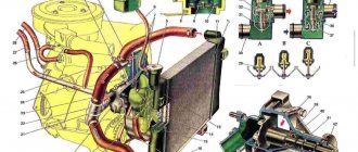
Engine cooling system
The cooling system is liquid, closed type, with forced circulation.
The tightness of the system is ensured by valves in the expansion tank plug. The inlet valve is normally open (the gap between it and the rubber gasket is 0.5–1.1 mm) - in this case, the system communicates with the expansion tank. When the engine heats up, the liquid expands and is forced into the tank; when it cools, it returns back. The inlet valve closes when there is a sharp increase in pressure in the system (boiling liquid), while the outlet valve is also closed. It opens when the pressure in the system reaches approximately 0.5 kgf/cm2, which increases the boiling point of the liquid and reduces its losses. The thermal operating conditions of the engine are maintained by a thermostat and a radiator fan. On a carburetor engine, the fan is mechanically driven and mounted on the coolant pump pulley. On an engine equipped with an injection system, two electric fans are installed in front of the radiator and are activated by command from the electronic engine control unit. Carburetor engine cooling system
Injection engine cooling system
1 – expansion tank; 2 – expansion tank plug; 3 – pipe for draining fluid from the heater radiator; 4 – hose for draining fluid from the heater radiator; 5 – heater tap; 6 – heater radiator; 7 – hose for supplying fluid to the heater radiator; 8 – hose for supplying fluid to the carburetor heating block; 9 – hose for draining fluid from the carburetor heating unit; 10 – thermal vacuum switch of the recirculation valve; 11 – thermostat bypass hose; 12 – coolant pump cover; 13 – fan impeller; 14 – coolant temperature sensor for the instrument cluster; 15 – radiator supply hose;
16 – radiator; 17 – radiator cap; 18 – radiator drain plug; 19 – fan casing; 20 – radiator outlet hose; 21 – coolant pump drive belt; 22 – coolant pump housing; 23 – hose for supplying coolant to the pump; 24 – thermostat; 25 – coolant supply hose to the throttle body; 26 – coolant drain hose from the throttle body; 27 – coolant temperature sensor for the injection system; 28 – electric fan impeller; 29 – electric motor; 30 – electric fan casing.
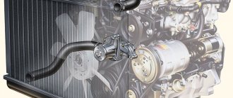
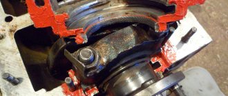
The coolant pump is a vane, centrifugal type, driven from the crankshaft pulley by a V-belt. The pump housing is aluminum. The roller rotates in a double-row bearing with a lifetime supply of lubricant. The outer ring of the bearing is locked with a screw. A pulley hub is pressed onto the front end of the roller, and a plastic impeller is pressed onto the rear end. For the correct position of the pump pulley groove, the distance from the mating surface of the pump cover to the outer end of the hub must be 84.4 ± 0.1 mm. When installing the cover with the gasket, check the gap of 0.9–1.3 mm between the impeller blades and the pump housing. To do this, you can use plasticine rollers: they are placed on equidistant impeller blades, a cover is installed, the nuts securing it are tightened, then the cover is removed and the remaining thickness of the plasticine is measured - it is equal to the gap.
Axial and radial play in the pump bearing that can be felt by hand is not allowed. If the bearing or self-pressing seal of the pump fails, it is recommended to replace the pump cover complete with the roller and impeller.
The redistribution of liquid flows is controlled by a thermostat with a solid heat-sensitive element. On a cold engine, the thermostat valve closes the pipe leading to the radiator, and the liquid circulates only in a small circle (through the thermostat bypass pipe), bypassing the radiator. The small circle includes the heater radiator, intake manifold, carburetor heating unit (on engine 21213) or throttle assembly (on engine 21214). At a temperature of 78–85°C, the valve begins to move, opening the main pipe; in this case, part of the liquid circulates in a large circle through the radiator. At a temperature of about 90°C, the main valve opens completely, and the bypass valve closes, and all the liquid circulates through the engine radiator. The main valve stroke must be at least 6.0 mm.
You can evaluate the serviceability of the thermostat by heating the lower radiator pipe: it should be cold until the liquid temperature (according to the indicator) reaches 80–85°C, and hot when it rises to 85–90°C. The thermostat is beyond repair. In case of malfunction, loss of tightness, or deformation of the pipes, it is replaced.
The radiator consists of two vertical plastic tanks (the left one has a baffle) and two horizontal rows of round aluminum tubes with pressed-on cooling plates. To increase cooling efficiency, the plates are stamped with a notch. The tubes are connected to the tanks through a rubber gasket. The liquid is supplied through the upper pipe and discharged through the lower. There is a coolant drain plug at the bottom of the left reservoir.
For better radiator airflow, casings are designed to direct air flow from the fan(s).
On the 21213 engine, the main fan shroud consists of two halves (lower and upper), the lower half has a rubber seal on the radiator side. An additional guide casing is installed in front of the radiator. On the 21214 engine, electric fans rotate in a casing in front of the radiator.
The expansion tank is made of translucent polyethylene, which allows you to visually monitor the fluid level (3–5 cm above the “MIN” mark on a cold engine).
To monitor the coolant temperature, a sensor is screwed into the engine cylinder head and is connected to a temperature gauge on the dashboard. An additional temperature sensor is installed in the exhaust pipe of the 21214 engine, which provides information to the electronic engine control unit (see here).
The heating system is described here.
Video
How to install additional cooling on a Niva?
- How to install additional cooling on a Niva?
- Features of the engine cooling system on the Niva
- What will be needed to improve the system
- How to install a fan on a Niva, detailed instructions
In 1994, the VAZ-21213 engine was developed, which took its place of honor under the hood of new and old Niva cars. Since then, the engine has been constantly modernized and improved, just like its cooling system. In this material we will talk about how to install a fan on a Niva, what you will need for this, as well as what features of the cooling system you need to pay special attention to.
- Features of the engine cooling system on the Niva
- What will be needed to improve the system
- How to install a fan on a Niva, detailed instructions
Features of the engine cooling system on the Niva
Before you start upgrading the “heart” of the car, it’s worth studying its features in detail, in particular the cooling system. On the Niva it is liquid, closed type and with forced circulation. The tightness of the entire system is ensured by the inlet and outlet valves in the expansion tank plug. When the engine heats up, the liquid expands and is forced into the reservoir; when the engine cools down, it’s the other way around.
The thermostat and radiator fan regulate the thermal operating conditions of the unit. On carbureted cars, the radiator cooling fan is located on the coolant pump pulley, and on cars with an engine equipped with an injection system, two electric fans are installed in front of the radiator. The latter are activated by the engine's electronic control unit.
There are three types of cooling fans: with a viscous coupling, with an electronic control unit and with a thermal switch.
The most popular are electric-driven fans, which consist of an electric motor, an electronic control unit, a temperature sensor and a fan switch relay. Fans with viscous couplings are most often installed by the manufacturer.
What will be needed to improve the system
In order to improve the Niva radiator cooling fan, you will need the following tools and consumables:
1. To install a temperature sensor - a tee;
2. Rubber shock absorbers;
3. Relays, clamps and terminals;
4. Fuse and mounting block;
5. Electronic control unit.
The sensor can be installed in three places: radiator, upper pipe or lower pipe.
Experts recommend choosing the latter option; in this case, you will be able to control the temperature at the radiator outlet.
Many car owners are concerned not only with the issue of improving old Niva models, but also with directly replacing the cooling fan in the event of a breakdown. The factory circuit provides for a parallel connection of the fans, and they are turned on using two relays. On cars with a carburetor engine, the fans are turned on by a sensor on the radiator, and on cars with an injection engine - by the engine control unit. The method of replacement depends on this.
How to install a fan on a Niva, detailed instructions
On the classic Niva, the fan is installed on a pump, and its rotation speed depends on the engine speed. In modern vehicle operating conditions, this design can lead to engine overheating. This is why electric cooling fans are needed.
In order for the units to operate at both low and high speeds, the installation of an additional relay will be required.
Its control can be manual and/or automatic. The fan connection diagram differs depending on the engine type. Try new fans on old casings to avoid cutting out any additional openings. But the whole point of the connection lies in the correct connection of the relay and terminals.
Connection diagram in serial connection:
1. Place an additional (five-pin) relay near the fan. Pins 85 and 86 are the leads of the electromagnet coil, pin 30 is the moving contact, and 87 and 87a are the fixed contacts.
2. Remove the “-” wire from the chip connected to one of the fans and connect it to pin 87a, and connect the free space with a wire to pin 30.
3. Connect pin 87 to the “+” wire of the second fan.
4. Remove the wire from the standard relay socket and connect it to terminal 85, while connecting terminal 86 to vehicle ground.
5. You will have a free output of the standard relay, which must be connected to an additional power sensor.
On a Chevrolet Niva, the cooling system fans are connected identically. The circuit works as follows: when the temperature reaches the sensor response threshold, the relay will operate, which will lead to the flow of current to the positive brush of the first fan, then to the negative brush, and ultimately to the electric motor of the second unit. Installing electric fans on the Niva will help avoid constant vehicle noise, increase cross-country ability, reduce engine load, and also reduce fuel consumption.
Subscribe to our feeds on social networks such as Facebook, Vkontakte, Instagram, Pinterest, Yandex Zen, Twitter and Telegram: all the most interesting automotive events collected in one place.
The capacity of the VAZ-21213 and VAZ-21214 engine cooling system on Lada Niva and Lada 4x4 (including the interior heating system) is 10.7 liters. The cooling system uses coolant with a freezing point of no higher than minus 40 degrees.
Composition of the VAZ-21213 and VAZ-21214 engine cooling system on Lada Niva and Lada 4x4.
— Engine cooling jacket. It is cast and surrounds the cylinders in the engine block, combustion chambers and gas passages in the cylinder head and intake pipe. - Radiator. — Mechanically driven fan or two electric fans. - Expansion tank. — Thermostat. — Coolant pump. — Heater radiator.
Diagram of the cooling system of a VAZ-21213 carburetor engine on a Lada Niva.
Diagram of the cooling system of the VAZ-21214 injection engine on a Lada 4x4 car.
Water pump for the engine cooling system of VAZ-21213 and VAZ-21214 on Lada Niva and Lada 4x4.
Coolant pump is vane, centrifugal type. Driven from the crankshaft pulley by a V-belt. The pump housing is aluminum. The roller rotates in a double-row bearing with a “lifetime” supply of lubricant. The outer ring of the bearing is locked with a screw. The pulley hub is pressed onto the front end of the shaft. On the rear there is a plastic impeller.
For the correct position of the pump pulley groove, the distance from the mating surface of the pump cover to the outer end of the hub should be 84.3-84.5 mm. When installing a cover with a gasket, check the gap of 0.9-1.3 mm between the impeller blades and the pump housing. To do this, you can use plasticine rollers.
They are placed on equidistant impeller blades, the cover is installed, the nuts securing it are tightened, then the cover is removed and the remaining thickness of the plasticine is measured. It is equal to the gap. Axial and radial play in the pump bearing that can be felt by hand is not allowed. If the bearing or self-pressing seal of the pump fails, it is recommended to replace the pump cover complete with the roller and impeller.
Names and catalog numbers of parts for the water pump of the cooling system VAZ-21213, VAZ-2131-01.
Names and catalog numbers of the water pump drive of the engine cooling system of VAZ-21213 and VAZ-21214 on Lada Niva and Lada 4x4.
Fans of the VAZ-21213 and VAZ-21214 engine cooling system for Lada Niva and Lada 4x4.
For additional cooling of the radiator, Lada Niva cars with a VAZ-21213 carburetor engine are equipped with a six-bladed fan with a mechanical drive. The fan is mounted on the coolant pump pulley.
On Lada 4x4 cars with a VAZ-21214 injection engine, two electric fans with plastic multi-blade impellers are installed. Electric fans, complete with a casing, are mounted on the front surface of the radiator and force air through the radiator core into the engine compartment. The electric fans are turned on and off at the command of the electronic engine control unit. Depending on the coolant temperature.
Thermostat of the VAZ-21213 and VAZ-21214 engine cooling system on Lada Niva and Lada 4x4.
To maintain the normal operating temperature of the coolant, a thermostat with a solid temperature-sensitive element is installed in the cooling system of the VAZ-21213 and VAZ-21214 engines on Lada Niva and Lada 4x4. It covers a large circle of the system when the engine is not warmed up and the coolant temperature is low.
The thermostat has a main and bypass valve. On a cold engine, the thermostat valve closes the pipe leading to the radiator. And the liquid circulates only in a small circle (through the bypass pipe of the thermostat), bypassing the radiator.
At a temperature of 78-85 degrees, the valve begins to move, opening the main pipe. In this case, part of the liquid circulates in a large circle through the radiator. And at a temperature of about 90 degrees, the main valve opens completely, and the bypass valve closes. And all the fluid circulates through the engine radiator. The main valve stroke must be at least 6.0 mm.
You can evaluate the serviceability of the thermostat by heating the lower radiator pipe. It should be cold until the liquid temperature (according to the gauge) reaches 80-85 degrees. And hot when it rises to 85-90 degrees. The thermostat is not repairable. If there is a malfunction, loss of tightness, or deformation of the pipes, the thermostat is replaced.
Radiator for the engine cooling system of VAZ-21213 and VAZ-21214 on Lada Niva and Lada 4x4.
The radiator is horizontal, tubular-plate, aluminum with plastic tanks. It consists of two vertical plastic tanks and two horizontal rows of round aluminum tubes with pressed-on cooling plates. To increase cooling efficiency, the plates are stamped with a notch. The tubes are connected to the tanks through a rubber gasket.
Coolant is supplied through the upper pipe and discharged through the lower. There is a coolant drain plug at the bottom of the left reservoir. For better cooling of the radiator, there is a casing that directs the air flow from the fans.
Coolant is poured through the radiator neck. The radiator cap, in which the intake and exhaust valves are installed, is designed to maintain excess pressure in the system when the engine heats up.
When the engine is hot, the exhaust valve maintains increased pressure in the system. Due to this, the boiling point of the liquid increases. When it cools down, the inlet valve opens. By passing some of the liquid from the expansion tank into the radiator and thereby compensating for the decrease in liquid volume.
The serviceability of the plug valves is very important for the normal operation of the cooling system. But often when problems arise (coolant boiling, etc.), car enthusiasts pay attention only to the operation of the thermostat, forgetting to check the valves.
Names and catalog numbers of parts for the radiator of the cooling system VAZ-21213, VAZ-21214, VAZ-2131-01.
Leaking of the exhaust valve leads to a decrease in the boiling point of the coolant. And its jamming in the closed state leads to an emergency increase in pressure in the system. This may cause damage to the radiator and hoses.
Expansion tank.
The expansion tank is made of translucent plastic. This allows you to visually monitor the fluid level (30-50 mm above the MIN mark on a cold engine). There is a hole in the expansion tank plug. Therefore, in its internal cavity the pressure is always atmospheric.
Monitoring the coolant temperature in the engine cooling system of VAZ-21213 and VAZ-21214 on Lada Niva and Lada 4x4.
To monitor the coolant temperature, a sensor is screwed into the engine cylinder head, connected to the temperature indicator on the instrument panel. An additional temperature sensor is installed in the outlet pipe of the cylinder head, which provides information to the controller.
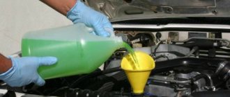
Replacing the coolant in the engine cooling system of VAZ-21213 and VAZ-21214 on Lada Niva and Lada 4x4.
According to the manufacturer's recommendation, the coolant should be replaced after 2 years of operation. Or after 60,000 kilometers. Whichever comes first. Also, if the coolant changes color to a tan color, replace it immediately. Since such a change indicates that inhibitory additives have been developed and the liquid has become aggressive towards the parts of the cooling system.
The engine cooling system of the VAZ-21213 and VAZ-21214 on the Lada Niva and Lada 4x4 is filled with ethylene glycol-based coolant. It is not recommended to fill the cooling system with water, since the coolant must contain anti-corrosion and anti-foaming additives, as well as additives that prevent scale deposits.
Procedure for replacing coolant.
1. Place the car on a flat, horizontal platform. If the site is sloped, position the vehicle so that the front is higher than the rear. Remove the oil pan protection and the engine compartment splash guard.
2. Open the heater tap. Move the crane control handle to the right until it stops. Place a container under the radiator drain plug of the cooling system and unscrew the plug. Unscrew the radiator cap of the cooling system by turning it counterclockwise.
3. Remove the drain plug from the cylinder block and drain the remaining coolant from the cylinder block passages. Having previously placed a container under it.
4. Remove the expansion tank plug. To drain fluid from the expansion tank, unfasten its fastening belt and, with the plug open, lift the tank and drain the fluid through the radiator.
5. Close the drain plugs on the radiator and cylinder block and install the expansion tank in place.
6. Fill the engine cooling system. Pour coolant into the radiator until its level is at the lower edge of the filler neck. Fill the expansion tank with liquid to the normal level. It is located approximately 50-70 mm from the edge of the filler neck. Close the expansion tank and radiator caps.
7. Start the engine and let it warm up to operating temperature (before turning on the fans of a car with an injection engine). After this, stop the engine, check the coolant level and, if necessary, add it to the expansion tank to the normal level
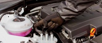
Removing an air lock from the engine cooling system of VAZ-21213 and VAZ-21214 on Lada Niva and Lada 4x4.
With the engine running, monitor the coolant temperature according to the gauge. If the arrow reaches the red zone and the injection engine fans do not turn on, turn on the heater and check what kind of air flows through it. If the heater supplies heated air, then the fans are most likely faulty. And if it is cold, it means that an air lock has formed in the engine cooling system.
To remove it, turn off the engine, let it cool and unscrew the radiator cap. Start the engine, let it run for 3-5 minutes and close the radiator cap. To ensure that air is removed from the cooling system of an injection engine, before adding liquid, disconnect the hose from the throttle assembly.
When pouring liquid into the radiator, at the moment the liquid begins to flow out of the throttle body pipe, put the hose on the pipe and tighten the hose clamp. After this, continue adding fluid to the normal level.
To better fill the cooling system of both engines without air locks, periodically squeeze the radiator hoses by hand. After a few days of using the car after replacing the coolant, check its level. If necessary, add coolant.
How does cooling work on the VAZ 2121 Niva?
The lifespan of a Niva SUV engine largely depends on how efficiently the VAZ-2121 cooling works. After all, overheating is the first enemy of the power unit, leading to expensive repairs.
This is why the serviceability of the components and elements of the cooling circuit is so important. In order to be able to service them and identify malfunctions, you need to understand what the circuit consists of and how the Niva’s cooling functions.
Vehicle cooling network design
The cooling system of the VAZ Niva is quite effective and has undergone virtually no changes since its creation. It includes the following units and elements:
Temperature control in the Niva engine cooling network is carried out in different ways. In the carburetor model VAZ-21213, a sensor is built into the cylinder head, connected to the temperature indicator on the dashboard. On the VAZ-21214 model, where the fuel is supplied by an injector, there is a second sensor mounted in the pipe on the cylinder head. It is connected to a controller that prepares the fuel mixture depending on the heating of the power unit and turns on the fans.
There are 2 more differences in the cooling design of engines with a carburetor and an injector:
- on cars with direct fuel injection, 2 electric fans are installed on the radiator instead of 1 mechanical;
- The heating pipes for the lower part of the carburetor in model 21214 provide heating for the throttle body.
In VAZ-2131 Chevrolet Niva cars, the cooling system is generally similar to a regular Niva with an injector. The VAZ-2131 heater radiator is not equipped with a tap, which is why antifreeze flows through it all year round.
Engine control system fuse box
Scheme
p, blockquote 8,0,0,0,0 —>
p, blockquote 9,0,0,0,0 —>
Designation
p, blockquote 10,0,0,0,0 —>
| 1 | 7.5A 2* Controller |
| 1 | 3: Electric fuel pump relay (contacts) Electric fuel pump |
| 1 | 30A 4.5* Cooling fan |
| 2 | 15A 1* Injectors Ignition coils ECM controller Right electric fan relay Left electric fan relay |
| 2 | 15A 2* Electric fuel pump relay (contacts) Electric fuel pump |
| 2 | 30A 3* Reserve |
| 2 | 30A 4.5* Cooling fan |
| 3,4 | 30A 1* Electric fans (right, left) Right electric fan relay Left electric fan relay |
| 3 | 15A 2* Main relay |
| 3 | 15A 3* Controller |
| 3 | 15A 4* Ignition coil, power supply for fan relay control, controller, injectors |
| 3 | 15A 5* Ignition relay |
| 4 | 15A 3* Main relay Electric fan relay (winding) Electric fuel pump relay (winding) Vehicle speed sensor Canister solenoid valve Oxygen sensor Mass air flow sensor Controller |
| 4,5 | 30A 2* Electric fan relay (winding) (right, left) Electric fan motor (right, left) |
| 4 | 15A 4* Mass air flow sensor, phase sensor, heating oxygen sensor (two), canister purge valve, DS |
| 4 | 15A 5* Electric fuel pump |
| 5 | 15A 1* Electric fuel pump Electric fuel pump relay |
1* - 2014-2016, 2* - 2010-2012, 3* - 2007-2008, 4* - Cars with Bosch ME17.9.7/M74 controllers, 5* - Cars with 7.9.7+ controllers.
p, blockquote 11,0,0,0,0 —>
Operating principle
The Niva's cooling circuit operates under pressure, since in normal mode it does not communicate with the atmosphere. The coolant is antifreeze with a freezing point of -40 °C. It is a solution of water with ethylene glycol, the amount to fill the system is 10.7 liters. It also boils at an elevated temperature, +110 °C.
The key element in the operation of the system is the thermostatic valve, which distributes fluid flows depending on the heating of the engine. Inside the thermostat there is a damper controlled by a temperature-sensitive element. When heated, it moves the damper, opening another path for the flow. In general, the scheme works according to the following algorithm:
In the summer and transition period in VAZ-21213 and 21214 cars, the passage of coolant through the heater radiator is limited by a tap. There is no such tap on the Chevrolet Niva; the heating is turned off by redirecting the air flow past the heat exchanger.
Operating principle
The cooling system of VAZ Niva models does not come into contact with the atmosphere in operating condition, and therefore requires pressure. The coolant is antifreeze with a freezing point of 40 degrees Celsius. The composition of the solution is water and ethylene glycol. The total volume of the cooling circuit is 10.7 liters. Antifreeze can boil after a temperature of +110 degrees Celsius.
The main functional unit in the system is the thermostatic valve, which distributes the coolant flow depending on the engine temperature. The thermostat, controlled by a temperature-sensitive sensor, regulates the direction of movement of antifreeze. A simplified work flow looks like this:
In summer and during transition periods in models with an injector, the movement of the cooler is limited by a special tap. The Niva Chevrolet model does not have such a blocker, so the heating is turned off by directing the air flow past the heat exchanger.
Possible faults
To avoid problems with engine overheating, it is necessary to monitor and maintain the Niva’s cooling system.
You should check the antifreeze level in the expansion tank more often. Due to the reliability of cooling, there are not many malfunctions in it:
- When the car heats up to maximum in any weather, and the main radiator pipes are cold, the thermostat has broken. The element is not repaired, only changed.
- Electric fans turn on at random, including when the engine is cold, but if they overheat, they may not start. This means that the sensor transmitting temperature data to the controller has failed and must be replaced.
- When the indicator on the panel gives inaccurate data or does not show the temperature, you need to change the second sensor located in the cylinder head.
- The fluid level in the tank is constantly decreasing. It is necessary to look for and eliminate leaks in the pipes or in one of the radiators.
It is important to periodically check for play in the water pump shaft. Its appearance indicates wear of the bearing; it is necessary to change the pump as soon as possible.
Possible problems and their causes
Like any vehicle system, the cooling circuit must be regularly monitored and worn parts replaced. The first indicator of possible problems will be the level of coolant in the expansion tank. The main breakdowns of the cooling systems of VAZ Niva models:
- Maximum engine heating with cold main radiator pipes means the thermostat is broken. The part cannot be repaired, only replaced.
- Electric fans in injection systems turn on uncontrollably or do not start at all. This is an indicator of a breakdown of the sensor that transmits data to the controller.
- A faulty sensor on the cylinder head causes incorrect data on the control panel or its complete absence.
- A constant decrease in antifreeze level indicates a leak somewhere in the circuit.
Engine cooling system for VAZ NIVA VAZ21213 and VAZ-21214
1. Coolant temperature sensor for the fuel injection system. 2. Radiator supply hose. 3. Tank cap. 4. Expansion tank. 5. Radiator cap. 6. Hose from the radiator to the expansion tank. 7. Cooling jacket. 8. Filler neck. 9. Plug inlet valve. 10. Exhaust (steam) valve of the plug. 11. Left radiator tank. 12. Radiator core. 13. Right radiator tank. 14. Fan impeller. 15. Turbulizer. 16. Rubber radiator support. 17. Fan shroud. 18. Fan belt. 19. Radiator outlet hose. 20. Coolant pump. 21. Coolant supply hose to the pump. 22. Thermostat. 23. Thermostat bypass hose. 24. Fluid drain pipe from the heater radiator. 25. Fluid drain hose from the carburetor heating unit. 26. Fluid supply hose to the carburetor heating unit. 27. Fluid drainage hose from the heater radiator. 28. Fluid supply hose to the heater radiator. 29. Rubber insert. 30. Inlet pipe (from the radiator). 31. Main valve. 32. Thermostat housing. 33. Bypass valve. 34. Overflow hose connection. 35. Coolant supply pipe to the pump. 36. Thermostat cover. 37. Piston. 38. Pump cover. 39. Thrust seal ring of the oil seal. 40. Oil seal. 41. Pump roller bearing. 42. Fan pulley hub. 43. Locking screw. 44. Pump roller. 45. Pump housing. 46. Pump impeller. 47. Intake pipe. I. Thermostat operation diagram. A. Liquid temperature is less than 80oC. B. Liquid temperature is from 80 to 94oC. C. Liquid temperature is more than 94oC.
The engine cooling system is liquid, closed, with forced circulation of coolant. The system is filled with Tosol D-40 coolant and an aqueous solution of Tosol-A antifreeze (concentrated ethylene glycol with anti-corrosion and anti-foaming additives with a density of 1.078-1.085 g/cm2).
The cooling system is filled with 10.7 liters, including the interior heating system. The fluid level in the expansion tank should be 3-4 cm above the “MIN” mark, checked on a cold engine (at 15-20°C).
To monitor the coolant temperature, there is a sensor installed in the cylinder head and a pointer on the instrument panel.
The cooling system includes: coolant pump 20, cooling jackets for the block and cylinder head, thermostat 22, fan, radiator, expansion tank 4, pipelines and hoses. When the engine is running, liquid heated in the cooling jackets flows through the outlet pipe through hoses 2 and 23 into the radiator or thermostat, depending on the position of the thermostat valves. Next, the cooled liquid is sucked in by pump 20 and supplied again to the cooling jackets. The coolant pump is a centrifugal type, driven from the crankshaft pulley by a V-belt that drives the generator.
The pump housing 45 and cover 38 are cast from aluminum alloy. In the cover, in bearing 41, which is locked with a screw 43, a roller 44 is installed. Bearing 41 is double-row, non-separable, without an inner race. The bearing is filled with Litol-24 grease during assembly and is not subsequently lubricated.
A cast iron impeller 46 is pressed onto the roller on one side, and the hub 42 of the pump drive pulley is pressed onto the other side. The end of the impeller in contact with the sealing ring is hardened with high frequency currents to a depth of 3 mm. The sealing ring is pressed against the impeller by the oil seal spring through a rubber collar. Oil seal 40 is non-separable and consists of an outer brass ring, a rubber cuff and a spring. The oil seal is pressed into the pump cover 38. The pump is driven by a V-belt 18.
The fan is a six-blade impeller 14 made of plastic, which is bolted to the hub 42 of the pump drive pulley. The fan blades have a variable radius installation angle and, to reduce noise, a variable pitch along the hub. For better operating efficiency, the fan is located in a casing 17, which is bolted to the radiator brackets.
Radiator and expansion tank. The radiator is collapsible, with plastic tanks 11 and 13, with two rows of aluminum horizontal tubes and aluminum cooling plates. The radiator core 12 is sealed with the tanks using rubber gaskets. For better cooling efficiency of the liquid, turbulators 15 are installed in the tubes. The radiator is mounted on rubber supports 16 and bolted to the front of the body. The filler neck of the radiator is closed with a plug 5 and connected by a hose to a translucent plastic expansion tank 4. The radiator plug has inlet 9 and outlet 10 (steam) valves, through which the radiator is connected to the expansion tank. The inlet valve 9 is not pressed against the gasket (the gap is 0.5-1.1 mm) and allows the inlet and outlet of coolant into the expansion tank when the engine is heating and cooling.
When the liquid boils or a sharp increase in temperature due to low throughput, the inlet valve does not have time to release liquid into the expansion tank and closes, disconnecting the cooling system from the expansion tank. When the pressure increases when heated to 50 kPa, the outlet valve 10 opens, and part of the coolant is transferred into the expansion tank. Thermostat and cooling system operation. The cooling system thermostat accelerates engine warm-up and maintains the required thermal operating conditions of the engine. At optimal thermal conditions, the coolant temperature should be in the range of 85-95°C. The temperature values maintained by the thermostat are indicated on its bottom.
Thermostat 22 consists of a body and a cover, which are rolled together with the seat of the main valve 31. The thermostat has three pipes: an inlet pipe for inlet of coolant from the radiator, a pipe bypass hose 23 for bypassing liquid from the cylinder head to the thermostat, and a pipe for supplying coolant to the pump. 20.
The main valve 31 is installed on the thermoelement glass, in which a rubber insert 29 is rolled. The rubber insert contains a polished steel piston mounted on a stationary holder. Between the walls and the rubber insert there is a heat-sensitive solid filler. The main valve 31 is pressed against the seat by a spring. Two posts are attached to the valve, on which a bypass valve 33 is installed, pressed by a spring.
The thermostat, depending on the temperature of the coolant, automatically turns on or off the radiator of the cooling system and bypasses the liquid through the radiator or bypassing it
On a cold engine, when the coolant temperature is below 80°C, the main valve is closed and the bypass valve is open. In this case, the liquid circulates through the hose 23 through the bypass valve 33 into the pump 20, bypassing the radiator (in a small circle). This ensures quick warm-up of the engine.
If the liquid temperature rises above 94 ° C, the solid filler of the thermostat expands, compresses the rubber insert 29 and pushes out the piston, moving the main valve 31 until it is completely open. The bypass valve 33 closes completely. In this case, the liquid circulates in a large circle: from the cooling jackets through hose 2 to the radiator and then through hose 19 through the main thermostat valve it enters pump 20, which is again sent to the engine cooling jackets.
Within temperatures of 80-94°C, the thermostat valves are in intermediate positions, and the coolant circulates in both small and large circles. The opening value of the main valve ensures gradual mixing of liquid cooled in the radiator, thereby achieving the best thermal operating conditions of the engine.
Electrical equipment of the VAZ 21214 car
Symbols on the diagram
1. Left front light. 2. Headlights. 3. Coolant temperature sensor. 4. Sound signal. 5. Throttle position sensor. 6. Mass air flow sensor. 7. Electromagnetic valve for adsorber purge. 8. Injectors. 9. Right front lamp. 10. Side direction indicators. 11. Rechargeable battery. 12. Electric heater motor. 13. Additional resistor for the heater motor. 14. Differential lock warning lamp switch.15. Windshield wiper relay. 16. Starter 21214. 17. Windshield wiper motor.18. Generator VAZ-21214. 19. Windshield washer motor.20. Ignition module. 21. Spark plugs.22. Controller. 23. Idle speed control. 24. APS status indicator. 25. Temperature indicator sensor.26. Oil pressure warning light sensor. 27. Socket for portable lamp(*). 28. Brake fluid level warning lamp switch. 29. Diagnostic block. 30. Relay for turning on the heated rear window. 31. Headlight high beam relay. 32. Relay for low beam headlights. 33. Electric fuel pump with fuel level sensor. 34. Starter activation relay. 35. Additional fuse block.36. Main fuse block. 37. Relay-breaker for direction indicators and hazard warning lights. 38. Reversing light switch. 39. Brake light switch. 40. Cigarette lighter VAZ-21214. 41. External lighting switch.42. Illumination lamps for heater control levers. 43. Rear fog light switch. 44. Rear window heating switch. 45. Heater motor switch. 46. Rear window wiper and washer switch. 47. Hazard switch. 48. Ignition switch. 49. Instrument lighting switch. 50. Windshield wiper switch. 51. Windshield washer switch. 52. Horn switch. 53. Turn signal switch. 54. Headlight switch. 55. Electric fuel pump relay. 56. Vehicle speed sensor. 57. Lamp switches located in the door pillars. 58. Interior lamps. 59. Rear window washer motor. 60. Instrument cluster. 61. Parking brake warning lamp switch. 62. Main relay. 63. Tail lights. 64. License plate lights. 65. Rear window wiper motor. 66. Rear window heating element. 67. Crankshaft position sensor. 68. Knock sensor. 69. VAZ oxygen sensor. 70. Electric fan relay. 71. Electric fans. 72. Injection system fuse block. 73. To the interior lamp. 74. To the courtesy light switch in the driver's door. 75. APS control unit.
How to change antifreeze on a VAZ 21214 Niva
The Niva SUV, in all modifications, is very popular in Russian spaces. This is due to good maintainability, low price and excellent maneuverability. To ensure reliable operation, you should undergo all maintenance on time, in particular, replace the coolant.
The liquid system with forced circulation of the VAZ 21214 car is designed for effective heat removal. It fully copes with its task, you just need to keep it in good condition.
Main element device
As for the cooling radiator, it is impossible to imagine the operation of the engine as a whole without it. It is represented by these components:
- upper and lower tanks;
- core;
- fastening parts.
Its main purpose is to cool the mixture coming from the water jacket to the required temperature standard. Good thermal conductivity is facilitated by the fact that it is usually made of brass. The core contains transverse plates. Once here, the reagent is divided into many streams - this allows you to get a more effective result.
The principle of operation goes like this:
- The pump constantly “moves” liquid into the VAZ 21214.
- The system operates in such a way that water circulates in a circle, washing the heated walls of the blocks and cylinder.
- In this case, engine overheating can be avoided, and heat will be guaranteed to be removed from important parts.
- Then the mixture goes through the radiator, and after that it is released into the environment.
- Thus, the cyclicity is completed - now the cooled liquid will have to repeat it again for the VAZ 21214.
Replacing antifreeze VAZ 21214
Replacing the coolant is a regulated maintenance procedure, which is prescribed in the operating instructions. There is nothing complicated about it if you clearly and carefully follow the described action plan.
Suitable for Niva cars:
Coolant drain
Before starting the draining procedure, you should prepare tools, containers for used antifreeze, as well as new liquids for subsequent refilling. If protection is installed under the engine, it can also be removed for convenience.
Next, we perform the procedure for draining the liquid from the VAZ 21214 (Niva):
- turn the temperature regulator in the cabin to the maximum position to the right (Fig. 1);
Flushing the cooling system
If there are deposits in the drained liquid or there is a transition from antifreeze to antifreeze, the system should be flushed. To do this you need to do the following:
- Flush the system with plain water through the expansion tank of the VAZ 21214. The plugs must be open;
- tighten the drain plug and bolt;
- fill the system with a flushing agent (you can use Liqui Moly Kuhlerreiniger or Lavr cooling system flush) with distilled water (6-7 liters);
- start the engine. Warm up to 90 degrees;
- leave it idling for 5-10 minutes, depending on the contamination of the system;
- muffle it. Allow the engine to cool to approximately 60 degrees;
- drain the flush using the same steps as removing the old fluid;
- tighten both plugs;
- fill with distilled water to rinse the cooling system;
- start the car and warm up to 90 degrees;
- turn off and let cool to 60 degrees, drain;
- repeat steps 8, 9, 10 and 11 if necessary.
Filling antifreeze into Niva 21214, 21213 without air locks
To fill new fluid into the cooling system, you can use the instructions described in the book on car repair and operation. But when doing this, motorists very often end up with air jams.
So, let's start filling it correctly:
- before filling, unscrew the hoses supplying antifreeze to the throttle valve heating unit and lift them slightly up (Fig. 1);
The filling of the liquid is completed, all that remains is to wipe off the spilled antifreeze and wait for the engine to cool. With the car now cooled down, check the level in the expansion tank again and top up if necessary.
Replacement frequency, how much and what kind of fluid is needed
According to the manufacturer's recommendation, it is necessary to replace antifreeze or antifreeze on VAZ-21214 cars every 3 years or after a mileage of 60 thousand kilometers. If the car is used in more severe conditions, then it is advisable to replace it more often - every 30-40 thousand kilometers.
In addition to the recommended coolant change intervals, there are other reasons why it is necessary to change the fluid in a car's cooling system:
- loss of coolant properties. You can check the quality of the antifreeze used using a test strip, which is sold in the same places where the liquid itself is sold. Place the strip in the expansion tank, then pull it out. The strip comes with a color scale, according to which you can understand how much longer the car can be used before replacing the coolant;
- change in color of the coolant to tan or red. This means that rust has appeared in it;
- the appearance of sediments, flakes and dense formations in the liquid.
The coolant for the VAZ 21214 Niva injector should have a freezing point no higher than -40 degrees. Typically, the manufacturer fills in TOSOL TS-40 (manufacturer in Dzerzhinsk). When replacing antifreeze, it can be replaced with antifreeze with G12 approval; it is safer for the entire cooling system. You can also use original Lada G12 antifreeze, which is suitable for all cars of this manufacturer.
Antifreeze volume table
| Model Niva | Engine capacity | Antifreeze volume | Original/recommended fluid |
| VAZ 21214 | 1.7 | 10.7 | Lada G12, TOSOL TS-40 |
| VAZ 21213 | 1.6-1.7 | 10.7 | |
| VAZ 2121 | 1.4-1.8 | 10.6 | |
| VAZ 2131 | 1.7 | 10.7 |
Replacing the heater valve VAZ 21214 Niva without draining antifreeze
Niva cars sometimes have problems associated with the failure of some parts of the cooling system, such as a thermostat or pump. If they break down, they are replaced as an assembly, fortunately they are not expensive. Also a common problem are leaking hoses or a cracked expansion tank, which also needs to be replaced.
But there is another problem with the VAZ 21214, a leaking heater valve. Because of this, there may be a smell of antifreeze in the cabin, wet floor mats on the front passenger side, or the heater may not work.
There are several ways to replace a faulty faucet:
- complete draining of antifreeze from the system;
- clamp the stove pipes with special clamps;
- Place your Niva on a slope, with the hood down.
But there is another option that is more clear and simple. To do this, you need to disconnect the pipes going to the stove under the hood, point them upward and fix them in this position. The next step is to remove the stove itself:
- unscrew the console;
- disconnect the latches securing the stove;
- there is no need to disconnect the buttons;
- move the radiator assembly, along with the tap and pipes, towards the driver;
- we take out the entire structure through the space between the steering wheel and pedals;
- That's it, you can change the tap itself.
After replacement, reassemble in reverse order. As you can see, this operation is quite simple, and antifreeze will not leak into the cabin. And the procedure takes only 40 minutes, even for an unprepared person.
Design Features
The cooling principle for the VAZ 21214 itself is liquid (which means circulation will occur in the reverse order). Filling is carried out using an expansion tank.
The reagent here is water with ethylene glycol. It will freeze only at the lowest possible temperatures, and with the help of various additives it can also increase the service life of the oil seal, as well as slow down the corrosion process of all other parts of the car
The cooling system for this brand of car will include the following components:
- radiator;
- heat exchanger located at the storage tank;
- radiator part;
- expansion tank;
- thermostat;
- centrifugal pump;
- radiator fan;
- pipes;
- control details;
- the so-called engine “cooling” jacket;
- a pipe that drains liquid from the heating radiator;
- liquid supply hose to the heating radiator;
- coolant pump cover.
This also includes both the numerous inlets and outlet channels that the system has.