Crankshaft position sensor Designed to synchronize the ignition system and the operation of fuel injectors in a gasoline injection engine. Accordingly, its breakdown will lead to the fact that the ignition will be in a hurry or delayed. This will lead to incomplete combustion of the fuel mixture, unstable engine operation or complete failure.
Currently, there are three types of sensors - induction, based on the Hall effect, and optical. However, the most common sensors are those of the first type (induction). Next, we will talk to you about possible malfunctions and methods for eliminating them.
The device and where the crankshaft position sensor is located
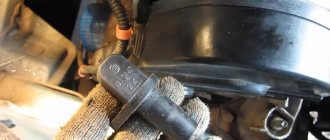
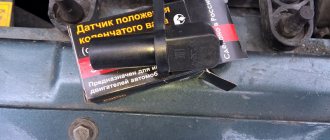
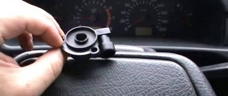
The electrical sensor plays an important role in the proper operation of the power plant, so all car manufacturers place it within easy reach for inspection and repair. The DPKV is located on the right side of the engine, next to the flywheel in the area of the cylinder block. You need to look above the pan, closer to the starter and coolant outlet pipes.
Crankshaft position sensor location
It is usually secured with one or two bolts (depending on the modification) and has a small wire with a contact chip. The element is coated with an elastic polymer that is resistant to oils and high temperatures
DPKV position relative to the mark
The shaft position is determined by two missing teeth or a dedicated control one (depending on the type of flywheel). DPKV “notices” this visually and using electromechanical processes. There are three types of controller.
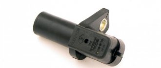
With Hall sensor
Works with a magnet mounted on the flywheel. Whenever it passes the sensor, a direct current is excited in the DPKV. This is recorded by the synchronizing disk and the information is transmitted to the engine control unit.
DPKV with Hall sensor
Optic
The device has an LED. Works in conjunction with a receiver. The beam always leaves and is reflected. When the glow is interrupted, it means that the control tooth has passed by the controller. It is used to determine the position of the crankshaft.
Optical DPKV
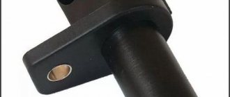
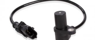
Inductive
Contains inside a magnetized coil that responds to an electromagnetic field. When the indicators change, a mark is recorded indicating the specific position of the pulley on the shaft.
Inductive DPKV
The last type is the most common and is installed on all modern cars with a fuel injection system into the engine. In addition to the position of the crankshaft, it is able to determine the rotation speed, therefore it is more functional.
DPKV location - design features
Typically this sensor is located near the alternator belt drive pulley. On this pulley there is usually a gear ring made around the circumference, the so-called synchronization disk. It is to the rotation of this disk that the sensor responds.
It is worth noting that in order to accurately obtain data on the rotation of the crankshaft, the DCPV is located at a certain distance from the disk.
For a correctly installed device, the distance between its core and the top of any tooth should be 0.6-1.5 mm.
The location of the DKPV is not the most convenient, but it is quite possible to get to it.
Cars use several different DPKVs in design and operating principles:
- induction (one of the most common);
- sensor using the Hall effect;
- Optic.
We won’t talk about the design and operation features of each of them for now; let’s move straight to the malfunctions.
Symptoms of a problem
To understand what signs of a malfunction may relate to the DPKV, let’s briefly consider its participation in engine operation. Asymmetrical projections on the crankshaft sequentially act on the connecting rods, pushing the pistons in the cylinders. The latter compress the air and pump up the compression. At the same time, the timing belt supplies the required amount of air to the cylinders through the cylinder head.
The engine control system “understands” the position of all participants, based on the DPCV data (provided that the timing drive is installed correctly), and opens the injectors to release gasoline. A spark is supplied from the ignition coils to the spark plugs, and the air-fuel mixture ignites. The engine runs smoothly and does not jerk.
If the crankshaft sensor malfunctions, the synchronization of the process is disrupted. The engine ECU does not know at what point to supply gasoline, which affects the operation of the internal combustion engine.
Diagnostics will help you find the cause of the breakdown, but more on that below.
Among the signs of malfunction indicating a possible breakdown of the DPKV there are:
- the Check Engine icon lights up on the dashboard;
- loss of vehicle dynamics;
- unstable engine speed;
- the engine stalls spontaneously;
- detonation when pressing the accelerator pedal;
- The engine jerks and shakes.
If the crankshaft sensor fails completely, the engine cannot be started at all. But this can only be established by checking, where the diagnostics will show the condition of other participants in the ignition system.
Popular brands:
Hyundai Creta
Symptoms
We have already become familiar with the types of crankshaft position sensors; now it is worth touching on the signs of their malfunction. Regardless of the design of the DPKV, the signs of its poor performance are always the same:
- The dynamic qualities of the car begin to decline noticeably. True, such a symptom indicates another malfunction, however, it makes sense to check the DPKV.
- The speed of the power unit changes spontaneously.
- When a car power plant is idling, the speed starts to “float” altogether.
- The occurrence of detonation due to dynamic load.
- If the electronic element fails altogether, then the engine will no longer start.
It is also worth considering that in the event of such a breakdown, the “Check Engine” emergency indicator always lights up. True, this will not specifically indicate a malfunction of the crankshaft position sensor, but it is a clear signal that some system in the engine has a malfunction.
Verification methods
The symptoms described above may be signs of a malfunction of more than just the crankshaft sensor. Such symptoms also apply to spark plugs, displaced marks in the timing belt assembly, high-voltage wires, and ignition coil. Here it is important to know how to test the controller.
Checking the DPKV will help make sure that the fault is in it, and not in a skipped timing belt or a dirty engine throttle valve.
There are several diagnostic methods. Since most DPKVs are inductive, we will consider testing just such a controller on the shaft.
wrench
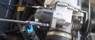
If the engine does not start and there are no measuring instruments or service stations nearby, you can check the position sensor with a wrench. For this method it is good to have a second person as an assistant:
- Open the hood and unscrew the sensor fixing bolt.
- Take the DPKV out and clean it of dirt.
- Turn on the ignition.
- Remove the cushion on the second row of seats so that you can better hear the operation of the fuel pump in the tank.
- Without removing the contact chip, apply a wrench to the end of the sensor.
- The second person should at this moment hear the fuel pump turning on.
This key test triggers the induction coil and simulates the passage of a pulley. If the fuel pump turns on every time a metal object is applied, then the controller responds to the position of the shaft. If the pump is not heard, then the symptom will definitely indicate a breakdown.
Oscilloscope
Checking the crankshaft sensor with an oscilloscope is done in two ways and gives a more accurate idea of the controller's response to the position of the shaft. In the first case, the action occurs with the engine turned off, but with the ignition on.
The sensor is removed from its place, and oscilloscope probes are applied to its contacts. Polarity doesn't matter here. Next, a metal object is passed in front of the end part of the sensor (you can use the same wrench). The coil should fire on metal, but instead of removing the back seat and listening to the sound of the fuel pump, the response will be visible on the oscilloscope screen.
Checking DPKV with an oscilloscope
A more accurate test can be performed with the engine running by connecting an oscilloscope parallel to the DPKV terminals. Then the program will show not only the reaction, but also a complete picture of the controller’s operation. The amplitude of the electromagnetic field will be displayed on the screen. It should have even upper and lower boundaries, as well as equal separation intervals indicating the passage of the control section. If there are more such pauses or the edges of the oscillogram are not smooth, it means that some of the flywheel’s teeth are broken off or severely worn out. This leads to incorrect sensor response. Then the issue is not a malfunction of the crankshaft sensor, but a mechanical part. The flywheel crown will need to be replaced.
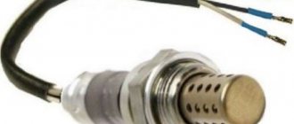
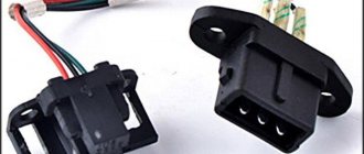
Multimeter
Checking the crankshaft sensor with a multimeter is performed in resistance measurement mode. To do this, the step switch is set to the appropriate position. The DPKV is removed outward, and the multimeter probes are inserted into the contacts.
Checking the sensor with a multimeter
Most sensors have a coil resistance range of 500-700 Ohms (you can find out more precisely from the characteristics of a specific model and the manufacturer’s data). Therefore, the device must be set to the upper value of 2000 Ohms. If the tester shows lower values, then the insulation of the coil winding is damaged. Such a malfunction requires replacement of the sensor. The absence of readings on the tester means that the circuit is broken and the DPKV is unsuitable for use.
In addition to resistance, some multimeters can test inductance. For the crankshaft position sensor, this indicator should be 200–400 mH. A significant deviation from the specified range indicates a controller malfunction.
Diagnostic scanner
Those who take a more professional approach to repairing their car have a diagnostic scanner in their tool kit. It helps to check not only the sensor, but also other parameters of the gasoline engine. Among products of Korean origin, OBD–2 Scan Tool Pro scanners are very popular.
Diagnostic scanner
The device is inserted into the car's standard connector and communicates with the ECU. Using a laptop, phone or PC, pairing occurs via Bluetooth or Wi-Fi network. A special program will be required. Collected errors are displayed on the screen. Among the fault codes related to the crankshaft position sensor: P0336 and P0335. Checking with a scanner consists of the presence of a signal from the position sensor and the ability to determine the reference mark to synchronize the subsequent operation of the engine.
Checking with an ohmmeter
If you don’t have a multimeter at hand, but have an ohmmeter, then that will also work. With the engine off, you will need to remove the crankshaft electric sensor and touch the device leads to the contacts in the connector. The operating parameters of the DPKV should be in the range of 500–700 Ohms. If the resistance is very high, it means that somewhere there is interference with the passage of electric current. If the indicator is too low, the integrity of the winding is compromised.
How to check the phase sensor
Checking the functionality of the internal combustion engine phase sensor is carried out using a diagnostic tool, as well as using an electronic multimeter capable of operating in DC voltage measurement mode. We will discuss an example of a test for phase sensors of a VAZ-2114 car. On models with a 16-valve engine, a sensor model 21120-3706040 is installed, and on 8-valve engines - 21110-3706040.
First of all, before diagnostics, the sensors must be removed from their mounting location. After this, you need to visually inspect the DF housing, as well as its contacts and terminal block. If there is dirt and/or debris on the contacts, it must be removed with alcohol or gasoline.
To check the sensor of the 8-valve engine 21110-3706040, it must be connected to a battery and an electronic multimeter according to the diagram shown in the figure.
Next, the verification algorithm will be as follows:
- Set the supply voltage to +13.5±0.5 Volts (you can use a regular car battery for power supply).
- In this case, the voltage between the signal wire and ground must be at least 90% of the supply (that is, 0.9V). If it is lower, and even more so equal or close to zero, then the sensor is faulty.
- Bring a steel plate to the end of the sensor (with which it is directed towards the camshaft reference).
- If the sensor is working properly, then the voltage between the signal wire and ground should be no more than 0.4 Volts. If more, it means the sensor is faulty.
- Remove the steel plate from the end of the sensor, the voltage on the signal wire should again return to the original 90% of the supply voltage.
To check the phase sensor of a 16-valve engine 21120-3706040, it must be connected to a power supply and a multimeter according to the diagram shown in the second figure.
To test the corresponding phase sensor, you will need a metal piece with a width of at least 20 mm, a length of at least 80 mm and a thickness of 0.5 mm. The verification algorithm will be similar, however, with other voltage values:
- Set the supply voltage on the sensor to +13.5±0.5 Volts.
- In this case, if the sensor is working properly, then the voltage between the signal wire and ground should not exceed 0.4 Volts.
- Place a pre-prepared steel piece into the sensor slot where the camshaft reference is placed.
- If the sensor is working properly, then the voltage on the signal wire should be at least 90% of the supply voltage.
- Remove the plate from the sensor, and the voltage should again drop to a value of no more than 0.4 Volts.
In principle, such checks can be performed without removing the sensor from its mounting location. However, to inspect it, it is better to remove it. Often, when checking a sensor, it makes sense to check the integrity of the wires, as well as the quality of the contacts. For example, there are cases when the chip does not hold the contact tightly, which is why the sensor does not receive a signal to the electronic control unit. Also, if possible, it is advisable to “ring” the wires going from the sensor to the ECU and to the relay (power wire).
In addition to checking with a multimeter, you need to check for relevant sensor errors using a diagnostic tool. If such errors are detected for the first time, you can try to reset them using software, or simply by disconnecting the negative terminal of the battery for a few seconds. If the error appears again, additional diagnostics are needed using the above algorithms.
Typical phase sensor errors:
- P0340 - no camshaft position sensor signal;
- P0341 - valve timing does not coincide with the compression/intake strokes of the cylinder-piston group;
- P0342 - the signal level in the electrical circuit of the DPRV is too low (detected when there is a short to ground);
- P0343 - the signal level from the meter exceeds the norm (usually occurs when the wiring is broken);
- P0339 - an intermittent signal is received from the sensor.
Thus, if these errors are detected, it is advisable to perform additional diagnostics as quickly as possible so that the engine operates in optimal operating mode.
Trouble-shooting
The check may show the inability of the electric sensor to detect the condition of the crankshaft. In this case, if the failure of the DPKV is confirmed, it will need to be replaced with a new one. But if the breakdown happened on the road and the nearest car shop or service station is far away, you can try to find and fix the problem yourself. Sometimes the problem lies not in the coil of the induction device, but in the contacts.
Cleaning from dirt
For example, a common problem is contamination of the working part with grease from the flywheel. The latter flies onto the sensor and covers it with a thick layer of dirt. Dust and sand, as well as metal shavings, stick to the top. All this creates interference with the operation of the element. In this case, you will need to unscrew one or two holding bolts, remove the DPKV out and thoroughly wipe its body protruding after the stop. Then return the device back and try to start the engine again.
Dirty PCV sensor
Broken contact
Another common problem is a broken wire. It often happens before the contact chip. At this point the wires bend, which leads to gradual refraction. Visually, a violation of the integrity of the conductor may not be noticeable, since the outer insulation remains intact.
To resolve the problem, remove the connector and pull the contact pins lightly towards you. The tattered one will come out and remain in your hands.
Repairs will require stripping the insulation and tying off the exposed ends. Then the area is insulated (you can use cambric or electrical tape). But this measure is temporary and will require subsequent soldering.
Contact contamination
Although the connector is protected by a rubber seal, it gradually loses elasticity and tightness. Because of this, moisture and dust penetrate inside. The corrosion process begins. The contacts oxidize and the circuit is interrupted. As a result, a serviceable DPKV ceases to detect the condition of the crankshaft and the engine stalls.
Dirt on DPKV contacts
To solve the problem, try cleaning the contact pins. They are located in the recesses and can be reached with a thin file or sandpaper rolled into a tube. Blow out any dust that has accumulated inside, restore the connection and try to start the engine.
Related Issues
If the DPKV “rings” and there is no violation in the integrity of the contacts, the breakdown may be associated with missing teeth on the flywheel. The electric sensor simply “confuses” the ECU, responding to additional “tags” formed. Only a mechanic at a service station can determine this. To repair, you will need to replace the flywheel crown.
The MAF (determines the mass air flow) also affects the operation of the DPKV and causes deviations in the readings. The problem is diagnosed in the service.
A figure-eight bend of the flywheel can mislead the crankshaft electric sensor, and this will require removing the box and replacing the deformed part.
Types of sensors and operating principles
There are several varieties, but the gap is fixed using a general method. Actually, they themselves can be like this:
- Induction
- Optical
- Hall sensors.
The operation of the induction sensor is based on the phenomenon of electromagnetic induction. While the crankshaft rotates, the teeth change the magnetic field of the crankshaft sensor, resulting in induced voltage pulses.
The optical analogue has an LED instead of a magnetized core. It emits a beam, which is perceived by a receiver located on the other side. Synchronization is also carried out using special teeth (grooves). The task of the last device is to detect interruptions in the light beam, due to which a voltage pulse is formed, and it is already sent to the ECU.
Hall sensors operate according to the physical effect of the same name. There is an integrated circuit that is located right behind the magnet and the teeth just sweep past it. When the teeth pass directly under the circuit, the magnitude of the magnetic field that penetrates the Hall element changes. Due to this, a millivolt voltage signal is generated. At the same time, the integrated circuit itself produces rectangular pulses and the area where two teeth are missing will be noticeably longer. Typically, the Hall sensor is three-pin - power supply +5 Volts (+12V), ground, signal output.