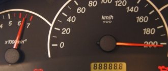
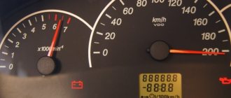
On Lada cars produced in 2001 - 2007 and subsequent ones, the manufacturer installs a BC capable of performing a self-diagnosis procedure. Thanks to this, the motorist can independently read the fault codes of the VAZ 2112 and determine the presence of a breakdown. Errors are reflected on the instrument display in the form of one or two-digit codes. The disadvantage of the procedure is the lack of an accurate determination of the location of the breakdown - self-diagnosis is only capable of a general determination of the circuit. Faults can also be read using additional equipment. The connected scanner provides detailed information about the specific location of the breakdown.
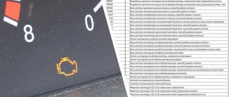
Deciphering error codes on the instrument panel of a VAZ-2112?
Below is a list of decoding codes for models 2107, 2110, 2111, 2112, 2114, 2115, injection engines with an on-board computer:
- 0102 - Low signal level of the mass air flow sensor
- 0103 - High signal level of the mass air flow sensor
- 0112 - Low level of intake air temperature sensor
- 0113 - Intake air temperature sensor high level
- 0115 - Incorrect coolant temperature sensor signal
- 0116 - Incorrect coolant temperature sensor signal
- 0117 - Low signal level of the coolant temperature sensor
- 0118 - High signal level of the coolant temperature sensor
- 0122 - Low signal level of the throttle position sensor
- 0123 - High signal level of the throttle position sensor
- 0130 - Incorrect signal from oxygen sensor 1
- 0131 - Low signal level of oxygen sensor 1
- 0132 - High signal level of crankshaft sensor 1
- 0133 - Slow response of oxygen sensor 1
- 0134 - No signal from oxygen sensor 1
- 0135 - Oxygen sensor 1 heater malfunction
- 0136 - Oxygen sensor 2 short to ground
[custom_ads_shortcode1]
- 0137 - Low signal level of oxygen sensor 2
- 0138 - High signal level of oxygen sensor 2
- 0140 - Open oxygen sensor 2
- 0141 - Oxygen sensor 2 heater malfunction
- 0171 - Mixture too lean
- 0172 - Mixture too rich
- 0201 — Open injector control circuit 1
- 0202 - Injector 2 control circuit open
- 0203 - Injector 3 control circuit open
- 0204 - Injector 4 control circuit open
- 0261 - Short to ground injector 1 circuit
- 0264 - Short to ground in injector 2 circuit
- 0267 - Short to ground in injector 3 circuit
- 0270 - Short to ground injector 4 circuit
- 0262 - Short circuit to +12V injector 1 circuit
- 0265 - Short circuit to +12V injector circuit 2
- 0268 - Short circuit to +12V injector circuit 3
- 0271 - Short circuit to +12V injector circuit 4
- 0300 - Many misfires
- 0301 - Misfire in cylinder 1
- 0302 - Misfire in cylinder 2
- 0303 - Misfire in cylinder 3
- 0304 - Misfire in cylinder 4
- 0325 - Open circuit of the knock sensor
- 0327 - Low signal level of the knock sensor
- 0328 - High signal level of the knock sensor
- 0335 - Incorrect crankshaft position sensor signal
- 0336 - Crankshaft position sensor signal error
- 0340 - Phase sensor error
- 0342 - Low signal level of the phase sensor
- 0343 - High level of phase sensor signal
- 0422 - Low efficiency of the neutralizer
- 0443 - Malfunction of the canister purge valve circuit
- 0444 - Short circuit or break in the adsorber purge valve
- 0445 - Short to ground of the canister purge valve
- 0480 - Cooling fan 1 circuit malfunction
- 0500 - Invalid speed sensor signal
- 0501 - Invalid speed sensor signal
- 0503 - Interruption of the speed sensor signal
- 0505 - Idle air control error
- 0506 - Low idle speed
- 0507 - High idle speed
- 0560 - Incorrect on-board voltage
- 0562 - Low voltage on-board network
- 0563 - High voltage on-board network
- 0601 - ROM error
- 0603 - External RAM error
- 0604 - Internal RAM error
- 0607 - Detonation channel malfunction
- 1102 - Low resistance of the oxygen sensor heater
- 1115 - Faulty oxygen sensor heating circuit
- 1123 - Rich mixture at idle
- 1124 - Lean mixture at idle
- 1127 - Rich mixture in Partial Load mode
- 1128 - Lean mixture in Partial Load mode
- 1135 - Oxygen sensor heater circuit 1 open, short circuit
- 1136 - Rich mixture in Low Load mode
- 1137 - Lean mixture in Low Load mode
- 1140 -Measured load differs from calculation
- 1171 - Low level CO potentiometer
- 1172 - High level CO potentiometer
- 1386 - Detonation channel test error
- 1410 - Canister purge valve control circuit short circuit to +12V
- 1425 - Canister purge valve control circuit short circuit to ground
- 1426 - Canister purge valve control circuit open
- 1500 - Open circuit in the fuel pump relay control circuit
- 1501 - Short circuit to ground of the fuel pump relay control circuit
- 1502 - Short circuit to +12V fuel pump relay control circuit
- 1509 - Overload of the idle air control control circuit
- 1513 - Idle air control circuit short circuit to ground
- 1514 - Idle air control circuit short circuit to +12V, open
- 1541 - Fuel pump relay control circuit open
- 1570 — Incorrect APS signal
- 1600 - No connection with APS
- 1602 — Loss of on-board voltage to the ECU
- 1603 - EEPROM error
- 1606 - Rough road sensor incorrect signal
- 1616 - Rough road sensor low signal
- 1612 - ECU reset error
- 1617 - Rough road sensor high signal
- 1620 - PROM error
- 1621 - RAM error
- 1622 - EEPROM error
- 1640 - EEPROM Test Error
- 1689 -Invalid error codes
- 0337 - Crankshaft position sensor, short to ground
- 0338 - Crankshaft position sensor, open circuit
- 0441 - Air flow through the valve is incorrect
- 0481 - Cooling fan 2 circuit malfunction
- 0615 - Starter relay circuit open
- 0616 - Starter relay circuit short circuit to ground
- 0617 - Starter relay circuit short circuit to +12V
- 1141 - Malfunction of the oxygen sensor heater 1 after the converter
- 230 - Fuel pump relay circuit malfunction
- 263 - Injector driver fault 1
- 266 - Faulty injector driver 2
- 269 - Injector 3 driver malfunction
- 272 - Faulty injector driver 4
- 650 - CheckEngine lamp circuit malfunction
[custom_ads_shortcode1]
conclusions
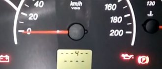
Finding and eliminating the cause of error 4 on the Lada Kalina turned out to be quite easy. Although deciphering error codes requires special knowledge, the necessary information can be found in this article.
Quite often, especially in the cold season, owners of a Lada Kalina car are faced with the fact that the car signals that error 4 has occurred. There is no need to immediately take it for a diagnostic examination at a car dealership, since it is quite possible to fix it yourself. The Lada Kalina car has an on-board computer, which is equipped with it during assembly. This is a necessary element with a variety of functionality, which is not only convenient to use, but also allows you to self-diagnose all errors that may occur in the car. In today's article we will talk in detail about error 4: why does it occur, what does it lead to, and how to eliminate it? We will also tell you how to check for other possible faults using the car’s on-board computer.
Decoding error codes of the VAZ electronic control unit
- P0030-Oxygen sensor heater before the converter, control circuit open
- P0031-Oxygen sensor heater before the converter, control circuit short to ground
- P0032-Oxygen sensor heater before the converter, control circuit shorted to board. net
- P0036-Oxygen sensor heater after the converter, control circuit open
- P0037-Oxygen sensor heater after the converter, control circuit short to ground
- P0038-Oxygen sensor heater after the converter, control circuit shorted to board. net
- P0102-Mass Air Flow Sensor Circuit Low Signal
- P0103-Mass air flow sensor circuit, high signal level
- P0112-Air temperature sensor circuit low signal
- P0113-Air temperature sensor circuit, high signal level
- P0116-Coolant temperature sensor circuit, signal out of acceptable range
- P0117-Coolant temperature sensor circuit low signal
- P0118-Coolant temperature sensor circuit, high signal level
- P0122 - Throttle Position Sensor Circuit Low Signal
- P0123 - Throttle Position Sensor Circuit High Signal
- P0130-Oxygen sensor before the converter is faulty
- P0131-Oxygen sensor circuit to converter, low output level
- P0132-Oxygen sensor circuit to converter, high output level
- P0133-Oxygen sensor circuit to the converter, slow response to changes in mixture composition
- P0134 - The oxygen sensor circuit to the converter is inactive
- P0136-Oxygen sensor after the converter is faulty
- P0137 - Oxygen sensor circuit after the converter, low signal level
- P0138-Oxygen sensor circuit after the converter, high signal level
- P0140 - The oxygen sensor circuit after the converter is inactive
- P0141-Oxygen sensor after the converter, heater is faulty
- P0171 - Fuel supply system too lean
- P0172 - Fuel system too rich
- P0201-Injector cylinder 1, control circuit open
- P0202-Injector cylinder 2, control circuit open
- P0203-Injector cylinder 3, control circuit open
- P0204-Injector cylinder 4, control circuit open
- P0217-Engine temperature is higher than permissible
- P0230-Fuel pump relay circuit malfunction
- P0261-Injector cylinder 1, control circuit short to ground
- P0263-Injector driver fault 1
- P0264-Injector cylinder 2, control circuit short to ground
- P0266-Injector driver fault 2
- P0267-Injector cylinder 3, control circuit short to ground
- P0269-Injector 3 driver malfunction
- P0270-Injector cylinder 4, control circuit short to ground
- P0262-Injector cylinder 1, control circuit short to on-board network
- P0265-Injector cylinder 2, control circuit shorted to on-board network
- P0268-Injector cylinder 3, control circuit short to on-board network
- P0271-Injector cylinder 4, control circuit short to on-board network
- P0272-Injector 4 driver malfunction
- P0300 - Random/multiple misfires detected
- P0301-Cylinder 1, misfire detected
- P0302-Cylinder 2, misfire detected
- P0303-Cylinder 3, misfire detected
- P0304-Cylinder 4, misfire detected
- P0326-Knock sensor circuit, signal output out of acceptable range
- P0327 - Knock sensor circuit low signal
- P0328 - Knock sensor circuit, high signal level
- P0335 - Crankshaft position sensor circuit is faulty
- P0336-Crankshaft position sensor circuit, signal out of acceptable range
- P0337 - Crankshaft position sensor, short to ground
- P0338-Crankshaft position sensor, open circuit
- P0340 - Camshaft Position Sensor Malfunction
- P0342-Phase sensor circuit, low signal level
- P0343-Phase sensor circuit, high signal level
- P0346-Phase sensor circuit, signal out of acceptable range
- P0351-Ignition coil of cylinder 1 (1-4), control circuit open
- P0352-Ignition coil of cylinder 2 (2-3), control circuit open
- P0353-Ignition coil of cylinder 3, control circuit open
- P0354-Ignition coil of cylinder 4, control circuit open
- P0363-Misfire detected, fuel supply to idle cylinders is turned off
- P0422 - Neutralizer efficiency below threshold
- P0441-Gasoline vapor recovery system, incorrect air flow through the canister purge valve
- P0444-Canister purge valve, control circuit open
- P0445-Canister purge valve, control circuit short to ground or on-board network
- P0480-Fan relay, control circuit open
- P0481-Cooling fan 2 circuit malfunction
- P0500-Vehicle speed sensor is faulty
- P0506-Idle system, low engine speed
- P0507-Idle system, high engine speed
- P0511-Idle speed control, control circuit faulty
- P0560-On-board network voltage is below the system operability threshold
- P0562-On-board voltage, low level
- P0563-On-board voltage, high level
- P0601-Engine management system controller, ROM checksum error
- P0615-Additional starter relay, control circuit open
- P0616-Additional starter relay, control circuit short to ground
- P0617-Additional starter relay, control circuit shorted to on-board network
- P0627-Fuel pump relay, control circuit open
- P0628-Fuel pump relay, control circuit short to ground
- P0629-Fuel pump relay, control circuit shorted to on-board network
- P0645-A/C compressor clutch relay, control circuit open
- P0646-A/C compressor clutch relay, control circuit short to ground
- P0647-A/C compressor clutch relay, control circuit shorted to board. net
- P0650-Malfunction indicator lamp, control circuit faulty
- P0654-Instrument cluster tachometer, control circuit faulty
- P0685-Main relay, control circuit open
- P0686-Main relay, control circuit short to ground
- P0687-Main relay, control circuit shorted to on-board network
- P0691-Fan relay, control circuit short to ground
- P0692-Fan relay, control circuit shorted to on-board network
- P1102 - Oxygen Sensor Heater Resistance Low
- P1115 - Oxygen sensor heating circuit faulty
- P1123 - Rich mixture at idle
- P1124 - Lean mixture in idle mode
- P1127 - Rich mixture at Partial Load
- P1128-Lean mixture in Partial Load mode
- P1135 - Oxygen sensor heater circuit 1 open, short circuit
- P1136 - Rich mixture in Light Load mode
- P1137 - Lean mixture in Light Load mode
- P1140 - Measured load differs from calculation
- P1141 - Oxygen sensor 1 heater malfunction after converter
- P1171-Low level CO potentiometer
- P1172-High level CO potentiometer
- P1301-Cylinder 1, misfire detected, critical for the converter
How to replace the coolant sensor
To work on removing the coolant temperature sensor, you need to remove at least part of the antifreeze from the system. The easiest way is to drain it from the radiator, but you will have to unscrew the plug on the cylinder block, since the sensor is located not far from this unit. Let's figure out how to drain the liquid from the system completely:
- Remove the negative terminal of the battery. Remove the middle mudguard in the engine compartment.
- Close the cap of the expansion tank tightly, place a container with a volume of at least 6 liters under the hole in the radiator, and remove the plug. To make the fluid drain faster, unscrew the cap on the expansion tank.
- To remove antifreeze from the cylinder block, you must additionally unscrew the plug on it. The exact instructions will depend on the number of valves in the engine. If your Kalina has an eight-valve system with a traction drive gearbox, then you need to find the drain hole under the ignition coil on the front side of the cylinder block. After this, place the container under it and remove the stopper. After this, all you have to do is unscrew the sensor, having first disconnected the block with wires from it.
If your Lada Kalina has a sixteen-valve system with a cable-driven gearbox, then you will need to remove the starter before draining the antifreeze. If you do not do this, you will fill this unit with coolant. The starter is held on by three bolts, but before removing them you need to disconnect the wiring.
Once you have removed the fluid, replace the plugs. Now you can start replacing the sensor itself. Remove the wire block from it, if you did not do this to check, then unscrew the controller using a 21 key. In its place you need to install a new element, having previously treated the thread with heat sealant. Connecting the wiring to the new sensor is not at all difficult - the chips have special notches for proper installation.
Return fluid to the cooling system through the expansion tank. It is necessary to use new antifreeze; the manufacturer recommends using red “Felix” for this. Then reassemble, warm up the engine to bleed the system. Check to see if antifreeze is leaking from the plugs or through the threads of the sensor. After the engine has warmed up, touch the pipes - they should all become warm. If everything is normal, you can begin testing the system and making a test drive. If the error persists, then most likely the on-board computer provided false information.
29 December 2014 566 240
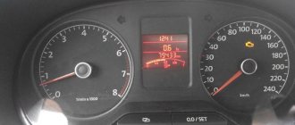
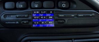
In the event of malfunctions in the operation of the vehicle, the engine electronic control unit (ECU) stores errors in memory. In the future, Kalina ECU errors can be read using an on-board computer or special equipment for car diagnostics. In addition to controller error codes, it is possible to perform Kalina self-diagnosis on the dashboard.
Advice
: To read errors in electronic units, car owners often use the ELM327 adapter (buy on Ali) and the OpenDiag application in their smartphone.
List of the most common VAZ Kalina errors
- P1302-Cylinder 2, misfire detected, critical for the converter
- P1303-Cylinder 3, misfire detected, critical for the converter
- P1304-Cylinder 4, misfire detected, critical for the converter
- P1386 - Knock Channel Test Error
- P1410-Canister purge valve control circuit short circuit to +12V
- P1425 - Canister purge valve control circuit short circuit to ground
- P1426 - Canister purge valve control circuit open
- P1500 - Fuel pump relay control circuit open
- P1501 - Fuel pump relay control circuit short to ground
- P1502-Short circuit to +12V fuel pump relay control circuit
- P1509 - Idle air control control circuit overload
- P1513 - Idle air control circuit short circuit to ground
- P1514-Idle air control circuit short circuit to +12V, open
- P1541 - Fuel pump relay control circuit open
- P1570-Immobilizer, circuit faulty
- P1602-Engine management system controller, power supply loss
- P1606-Rough road sensor circuit, signal out of acceptable range
- P1616 - Rough Road Sensor Circuit Low Signal
- P1617 - Rough road sensor circuit, high signal level
- P2301-Ignition coil of cylinder 1 (1-4), control circuit shorted to board. net
- P2303-Ignition coil of cylinder 2 (2-3), control circuit shorted to board. net
- P2305-Ignition coil of cylinder 3, control circuit shorted to board. net
- P2307-Ignition coil of cylinder 4, control circuit shorted to board. net
[custom_ads_shortcode1]
How to check the sensor
Since the cause of error 4 on the Lada Kalina is not always the failure of the controller, you need to learn how to diagnose it. First of all, inspect the wiring; if there are no breaks in it, then you need to move on to checking the sensor itself. Follow the instructions:
- Turn off the ignition and disconnect the wire connector from the coolant sensor. For the convenience of motorists, the block is marked “AB”.
- Place the probes of the electronic tester on contact B of this block and on engine ground. If the power circuit is not broken, the tester will show a voltage of 4.8 to 5.2 V. Otherwise, you need to check the power circuit.
- If the device shows sufficient voltage in the circuit, then you need to check the controller itself. To do this, place the tester probes on contact A and engine ground. Switch it to resistance measurement mode. If the circuit is grounded, the device will show a resistance of less than 1 ohm.
- The following measurements should be carried out on a warm and slightly cooled engine. The probes of the device are placed on the contacts of the sensor itself to measure its resistance. It is also important to know the temperature of the coolant; the hotter it is, the lower the resistance should be. The maximum resistance is achieved at negative temperatures, and at 100 degrees it is minimal - 180 Ohms.
If the sensor does not pass the warm-up test, it must be replaced. There are more complex ways to check the sensor, but to do this you will have to unscrew it and test it.
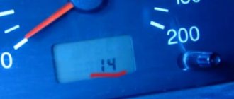
- VDO Panel Errors and Fault Codes
List of errors for cars with on-board diagnostics (OBD):
- P0105-Damage to the electrical circuit of the air flow meter sensor
- P0112-Low air temperature sensor signal
- P0113-Air temperature sensor signal high
- P0116-Damage to the electrical circuit of the coolant temperature sensor
- P0117-Coolant temperature sensor signal low
- P0118-Coolant temperature sensor signal high
- P0121-Damage to the electrical circuit of the throttle position sensor
- P0122 - Throttle position sensor signal low
- P0123-Throttle position sensor signal high
- P0130 - Damage to the electrical circuit of the oxygen sensor
- P0131-Oxygen sensor signal low
- P0132-Oxygen sensor signal high
- P0133 - Oxygen sensor slow response
- P0134 - Oxygen sensor performance low
- P0135-Damage to the electrical circuit of the heated oxygen sensor
- P0136-Damage to the electrical circuit of the downstream oxygen sensor
- P0137-Low signal level of the lower oxygen sensor
- P0138-Lower Oxygen Sensor Signal High
- P0141 - Damage to the electrical circuit of the heated oxygen sensor
- P0201-Damage to the electrical circuit of the fuel injector of cylinder 1
- P0202-Damage to the electrical circuit of the fuel injector of cylinder 2
- P0203-Damage to the electrical circuit of the fuel injector of cylinder 3
- P0204-Damage to the electrical circuit of the fuel injector of cylinder 4
- P0230-Damage to the fuel system electrical circuit
- P0300 - Random misfire
- P0301-Misfire in cylinder 1
- P0302-Misfire in cylinder 2
- P0303-Misfire in cylinder 3
- P0304-Misfire in cylinder 4
- P0326-Damage to the electrical circuit of the knock sensor
- P0335-Damage to the electrical circuit of the crankshaft angle sensor
- P0336-Random malfunction of the crankshaft angle sensor
- P0342-Camshaft position sensor signal low
- P0343-Camshaft position sensor signal high
- P0422 - Catalytic Converter Performance Low
- P0444-Open circuit of the activated carbon canister cleaning valve
- P0445 - Activated carbon canister cleaning valve circuit shorted
- P0501-Damage to the electrical circuit of the vehicle speed sensor
- P0506-Reduced idle speed
- P0507-Increased crankshaft speed at idle
- P0562-Undervoltage in the vehicle's on-board network
- P0563-Increased voltage in the vehicle’s on-board network
- P0606-ECM internal damage
- P1123-Rich fuel mixture
- P1124 - Fuel mixture lean
- P1127-Long-term over-enrichment of the fuel mixture
- P1128-Long-term leanness of the fuel mixture
- P1510 - The idle air system valve is constantly open due to a short circuit in the valve coil power supply circuit.
- P1513-The idle air system valve is constantly open due to an open circuit in the valve coil power supply
- P1552 - The idle air system valve is constantly closed due to the valve coil power supply circuit being shorted
- P1553-The idle air system valve is constantly closed due to an open circuit in the valve coil power supply
- P1529-Damage to transmission control unit
- P1586 - Inappropriate signal received from transmission
- P1605-Damage to the electrical circuit of the acceleration sensor
- P1606 - Inappropriate signal received from acceleration sensor
- P1611 - MIL Input Low
- P1613 - MIL Input High
- P1610-Damage to SMATRA immobilizer
- P1800-Damage to the immobilizer antenna
- P1801-Damage to immobilizer pulse transceiver
- P1803-ECM signal error
[custom_ads_shortcode2]
Diagnostics using a scanner
The method involves connecting an external computer with the program installed. This opens up more opportunities for car diagnostics. In this case, error codes for VAZ 2110 and VAZ 2112 consist of 5 characters.
Letter part:
- P – failure or malfunction of the power plant, transmission;
- B – body systems are damaged;
- C – a problem has been detected in the vehicle’s chassis;
- U – violation of pairing of different modules.
First digit:
- 0 – general value;
- 1/2 – manufacturer code;
- 3 – reserve.
Second digit:
- 1-2 – violation in the air-fuel mixture supply devices;
- 3 – malfunction of the ignition units;
- 4 – atmospheric emissions control device;
- 5 – malfunction of the engine speed or engine speed meters;
- 6 – failures in electronics;
- 7-8 – malfunction of the gearbox module;
- 9-0 – reserve unit.
The last two digits give the serial number of the breakdown and its location.
Prevention of breakdowns of electrical appliances
To prevent breakdowns of electrical circuits, you must follow a number of simple rules.
- Periodically check the contact connectors for oxidation or overheating. Rust disrupts the passage of impulses, which can be read by instruments as damage to the unit.
- Once a year, treat contacts with special oils. Lubricants prevent moisture from entering metals, which prolongs their service life.
- Replace dry wires in a timely manner. Cracked insulation can cause a short circuit.
Errors on the VAZ 2110 (2112) panel provide the user with complete information about the condition of the vehicle’s components and assemblies. If you know the decryptions, the driver can independently fix the breakdown of the vehicle electronics.
Source
Checking the coolant temperature sensor
I will not show tables with sensor resistance values at a certain temperature, since I think this method of checking is not entirely accurate. The simplest and fastest way to check the DTOZH is to simply remove the chip from it. The engine will go into emergency mode, the fan will turn on, and the fuel mixture will be prepared based on the readings of other sensors. If at the same time the engine begins to work better, then the sensor definitely needs to be changed.
For the next check of the coolant temperature sensor, you will need diagnostic equipment. First, you need to check the temperature readings on a cold engine (for example, in the morning). The readings must correspond to the ambient temperature. A slight error of 3-4 degrees is allowed. And after starting the engine, the temperature should rise smoothly, without jumping between readings. Those. if the temperature was 33 degrees, and then suddenly became 35 or 36 degrees, this indicates a sensor malfunction.