April 30, 2020 Lada.Online 49 997 8
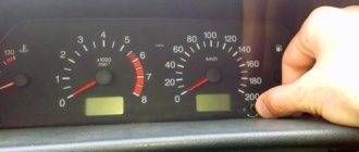
The fault indicator (Check Engine) on Lada 4×4 cars (VAZ 21214, 21314) is located in the instrument cluster. When the warning light turns on, it signals to the driver that the on-board diagnostic system has detected a malfunction of the ECM and the vehicle continues to move in emergency mode. To determine the cause, you should use a diagnostic tool, with which you can read error codes and decipher them according to the table below.
To carry out repair and maintenance work on the vehicle's engine management system, a diagnostic tool should be used. In service centers this can be a DST; for self-diagnosis, an ELM327 OBD-II scanner (price about 200 rubles, see the AliExpress catalog) and a smartphone with installed software (for example, OpenDiag), or an on-board computer installed in the car, are suitable for self-diagnosis.
Diagnostic codes of the ME17.9.7 controller
:
| Code | Description |
| P0030 | DC heater to neutralizer, circuit faulty |
| P0031 | DC heater before the neutralizer, control circuit shorted to ground |
| P0032 | DC heater before the neutralizer, control circuit closed to the on-board network |
| P0036 | DC heater after the neutralizer, the circuit is faulty |
| P0037 | DC heater after the neutralizer, control circuit short to ground |
| P0038 | DC heater after the neutralizer, control circuit closed to the on-board network |
| P0101 | Mass air flow sensor circuit, signal output from permissible range |
| P0102 | Mass Air Flow Sensor Circuit Low Signal |
| P0103 | Mass Air Flow Sensor Circuit High Signal |
| P0112 | Intake Air Temperature Sensor Circuit Low Signal |
| P0113 | Intake Air Temperature Sensor Circuit High Signal |
| P0116 | DTOZH circuit, signal output from permissible range |
| P0117 | DTOZH circuit, low signal level |
| P0118 | DTOZH circuit, high signal level |
| P0122 | TPS circuit A, low signal level |
| P0123 | TPS circuit A, high signal level |
| P0130 | The oxygen sensor before the converter is faulty |
| P0131 | DC circuit to the neutralizer, low output signal level |
| P0132 | DC circuit to the neutralizer, high output signal level |
| P0133 | DC circuit to the neutralizer, slow response to changes in mixture composition |
| P0134 | The oxygen sensor circuit to the converter is inactive |
| P0135 | Oxygen sensor to converter, heater faulty |
| P0136 | The oxygen sensor after the converter is faulty |
| P0137 | DC circuit after the neutralizer, low signal level |
| P0138 | DC circuit after the neutralizer, high signal level |
| P0140 | The oxygen sensor circuit after the converter is inactive |
| P0141 | Oxygen sensor after converter, heater faulty |
| P0171 | Fuel system too lean |
| P0172 | Fuel system too rich |
| P0201 | Cylinder 1 injector, circuit faulty |
| P0202 | Cylinder 2 injector, circuit faulty |
| P0203 | Cylinder 3 injector, circuit faulty |
| P0204 | Cylinder 4 injector, circuit faulty |
| P0217 | Engine temperature is higher than permissible |
| P0222 | TPS B circuit, low signal level |
| P0223 | TPS circuit B, high signal level |
| P0261 | Cylinder 1 injector, control circuit short to ground |
| P0262 | Cylinder 1 injector, control circuit shorted to on-board power supply |
| P0264 | Cylinder 2 injector, control circuit short to ground |
| P0265 | Cylinder 2 injector, control circuit shorted to on-board power supply |
| P0267 | Cylinder 3 injector control circuit short to ground |
| P0268 | Cylinder 3 injector, control circuit shorted to on-board power supply |
| P0270 | Cylinder 4 injector control circuit short to ground |
| P0271 | Cylinder 4 injector, control circuit shorted to on-board power supply |
| P0300 | Random/multiple misfires detected |
| P0301 | Cylinder 1, misfire detected |
| P0302 | Cylinder 2, misfire detected |
| P0303 | Cylinder 3, misfire detected |
| P0304 | Cylinder 4, misfire detected |
| P0327 | Knock Sensor Circuit Low Signal |
| P0335 | Crankshaft position sensor circuit is faulty |
| P0340 | Phase sensor is faulty |
| P0351 | Ignition coil of cylinder 1 (1-4), control circuit open |
| P0352 | Ignition coil of cylinder 2 (2-3), control circuit open |
| P0353 | Ignition coil of cylinder 3, control circuit breakage |
| P0354 | Ignition coil of cylinder 4, control circuit breakage |
| P0363 | Misfires detected, fuel supply to idle cylinders turned off |
| P0422 | Neutralizer efficiency below threshold |
| P0441 | Gasoline vapor recovery system, incorrect air flow through the control unit |
| P0444 | Canister purge valve, control circuit open |
| P0458 | Canister purge valve, control circuit short to ground |
| P0459 | Canister purge valve, control circuit shorted to on-board network |
| P0480 | Fan relay 1, control circuit open |
| P0481 | Fan Relay 2, Control Circuit Open |
| P0485 | Fan supply voltage is out of range |
| P0500 | Vehicle speed sensor is faulty |
| P0501 | Vehicle speed sensor, signal out of acceptable range |
| P0504 | Brake pedal A/B switches, signal mismatch |
| P0560 | Vehicle on-board voltage |
| P0561 | On-board voltage is unstable |
| P0562 | On-board voltage, low level |
| P0563 | On-board voltage, high level |
| P0606 | Court controller, ADC malfunction |
| P0615 | Add. starter relay, control circuit open |
| P0616 | Add. starter relay, control circuit short to ground |
| P0617 | Doi. starter relay, control circuit shorted to on-board network |
| P0627 | Fuel pump relay, control circuit open |
| P0628 | Fuel pump relay, control circuit short to ground |
| P0629 | Fuel pump relay, control circuit shorted to on-board network |
| P0645 | A/C compressor clutch relay, control circuit open |
| P0646 | A/C compressor clutch relay, control circuit short to ground |
| P0647 | Air conditioning compressor clutch relay, control circuit shorted to on-board network |
| P0691 | Fan Relay 1 Control Circuit Short to Ground |
| P0692 | Fan relay 1, control circuit shorted to on-board power supply |
| P0693 | Fan Relay 2 Control Circuit Short to Ground |
| P0694 | Fan relay 2, control circuit shorted to on-board power supply |
| P0830 | Clutch pedal switch, circuit faulty |
| P1335 | Throttle Actuator Control Monitoring, Throttle Position Out of Range |
| P1336 | Monitoring the control of the throttle valve drive, mismatch of signals from sensors “A” / “B” of the throttle position |
| P1388 | Monitoring the control of the throttle valve drive, mismatch of signals from sensors “A” / “B” of the accelerator pedal position |
| P1389 | Throttle actuator control monitoring, engine speed out of range |
| P1390 | Monitoring of throttle actuator control, incorrect response to a malfunction in the system |
| P1391 | Monitoring throttle actuator control, no response to system malfunction |
| P1545 | Throttle valve actuator, throttle position out of range |
| P1558 | Throttle valve actuator, return spring faulty |
| P1559 | Throttle valve actuator, throttle position at rest is outside the permissible range |
| P1564 | Throttle valve drive control system, throttle zero position adaptation interrupted due to low voltage |
| P1570 | Immobilizer, circuit faulty |
| P1578 | Throttle valve actuator control system, zero position adaptation value is out of range |
| P1579 | Throttle valve control system, throttle zero position adaptation interrupted due to external conditions |
| P1602 | Court controller, power supply loss |
| P1603 | Throttle actuator control monitoring, monitoring module malfunction |
| P2100 | Electric throttle actuator, control circuit open |
| P2101 | Electric throttle actuator, control circuit faulty |
| P2122 | Pedal Position Sensor A Circuit Low |
| P2123 | Pedal Position Sensor A Circuit High |
| P2127 | Pedal Position Sensor B Circuit Low |
| P2128 | Pedal Position Sensor B Circuit High |
| P2135 | Sensors “A” / “B” throttle position, signal mismatch |
| P2138 | Accelerator pedal position sensors “A” / “B”, signal mismatch |
| P2176 | Throttle valve control system, throttle zero position adaptation not performed |
| P2187 | Fuel system too lean at idle |
| P2188 | Fuel system too rich at idle |
| P2301 | Ignition coil of cylinder 1 (1-4), short circuit of the control circuit to the on-board network |
| P2304 | Ignition coil of cylinder 2 (2-3), short circuit of the control circuit to the on-board network |
| P2307 | Ignition coil of cylinder 3, short circuit of the control circuit to the on-board network |
| P2310 | Ignition coil of cylinder 4, control circuit shorted to on-board network |
For more details on each variator fault code, ask in the comments.
, we will try to answer you in more detail.
Fault codes
(Also some codes are presented here)
DIAGNOSTIC TROUBLE CODES FOR M CONTROLLER 7.9.7
| Code | Description |
| P0102 | Mass Air Flow Sensor Circuit Low Signal |
| P0103 | Mass Air Flow Sensor Circuit High Signal |
| P0112 | Intake Air Temperature Sensor Circuit Low Signal |
| P0113 | Intake Air Temperature Sensor Circuit High Signal |
| P0116 | Coolant temperature sensor circuit, signal out of range |
| P0117 | Coolant Temperature Sensor Circuit Low Signal |
| P0118 | Coolant Temperature Sensor Circuit High |
| P0122 | Throttle Position Sensor Circuit Low Signal |
| P0123 | Throttle Position Sensor Circuit High |
| P0130 | The oxygen sensor before the converter is faulty |
| P0131 | Oxygen sensor circuit to converter, low output level |
| P0132 | Oxygen sensor circuit to converter, high output signal level |
| P0133 | Oxygen sensor circuit to the converter, slow response to changes in mixture composition |
| P0134 | The oxygen sensor circuit to the converter is inactive |
| P0135 | The oxygen sensor after the converter is faulty |
| P0136 | The oxygen sensor after the converter is faulty |
| P0137 | Oxygen sensor circuit after the converter, low signal level |
| P0138 | Oxygen sensor circuit after the converter, high signal level |
| P0140 | The oxygen sensor circuit after the converter is inactive |
| P0141 | Oxygen sensor after converter, heater faulty |
| P0171 | Fuel system too lean |
| P0172 | Fuel system too rich |
| P0201 P0202 P0203 P0204 | Cylinder 1 injector (2,3,4), control target break |
| P0261 P0264 P0267 P0270 | Cylinder 1 injector (2,3,4), control target short to ground |
| P0262 P0265 P0271 | Cylinder 1 injector (2,3,4), control circuit shorted to on-board network |
| P0300 | Random/multiple misfires detected |
| P0301 P0302 P0303 P0304 | Cylinder 1 (2,3,4), misfire detected |
| P0327 | Knock Sensor Circuit Low Signal |
| P0328 | Knock Sensor Circuit High Signal |
| P0335 | Crankshaft position sensor circuit is faulty |
| P0336 | Crankshaft position sensor circuit, signal out of range |
| P0340 | Camshaft position sensor is faulty |
| P0342 | Camshaft Position Sensor Circuit Low Signal |
| P0343 | Camshaft Position Sensor Circuit High Signal |
| P0422 | Neutralizer efficiency below threshold |
| P0441 | Gasoline vapor recovery systems, incorrect air flow through the canister purge valve |
| P0480 | Fan relay 1 control circuit faulty |
| P0600 | Vehicle speed sensor is faulty |
| P0606 | Idle system, low engine speed |
| P0507 | Idle system, high engine speed |
| P0560 | On-board network voltage is below the system operability threshold |
| P0562 | On-board voltage, low level |
| P0663 | On-board voltage, high level |
| P0601 | ECM checksum error |
| P0615 | Additional starter relay, control circuit open |
| P0616 | Additional starter relay, control circuit short to ground |
| P0617 | Additional starter relay, control circuit closed to on-board network |
| P1135 | Oxygen sensor preheater, control circuit faulty |
| P1141 | Oxygen sensor heater after converter, control circuit faulty |
| P1386 | ECM knock detection channel error |
| P1410 | Canister purge valve, control circuit shorted to on-board network |
| P1425 | Canister purge valve, control circuit short to ground |
| P1426 | Canister purge valve, control circuit open |
| P1501 | Fuel pump relay, control circuit short to ground |
| P1502 | Fuel pump relay, control circuit shorted to on-board network |
| P1513 | Idle speed control, control circuit short to ground |
| P1514 | Idle air control control circuit faulty |
| P1541 | Fuel pump switch, control circuit open |
| P1570 | Immobilizer, circuit faulty |
| P1602 | HUD controller loss of supply voltage |
| P1606 | Rough road sensor circuit, signal out of acceptable range |
| P1616 | Rough Road Sensor Circuit Low Signal |
| P1617 | Rough Road Sensor Circuit High Signal |
| P1640 | ECM EEPROM read-write error |
Video
Source
VAZ (LADA) errors via OBDI protocol. Self-diagnosis.
1 — Malfunction of the engine control unit.
2 — The voltage in the on-board network is too high.
3 — Malfunction in the electrical circuit of the fuel level sensor.
4 — Malfunction in the electrical circuit of the antifreeze controller.
5 — Error in external temperature controller.
6 — Overheating of the engine (power unit)
7 — Emergency oil pressure in the engine.
8 — The voltage in the vehicle's electrical network is too low.
9 — Low battery level (battery is discharged)
12 — Malfunction in the electrical circuit of the malfunction indicator located on the instrument panel.
13 — No data (loss of communication) from the oxygen sensor (lambda probe)
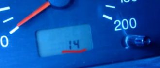
14 — High signal level of the coolant temperature sensor (antifreeze).
15 — Malfunction in the electrical circuit of the coolant temperature controller.
16 — Increased voltage in the vehicle’s electrical network
17 — Low voltage in the on-board network
19 — Malfunction in the electrical circuit of the crankshaft position sensor.
21 — Malfunction in the throttle position regulator.
22 — Low signal level of the throttle position sensor
23 — High signal level of the intake air temperature sensor
24 — Malfunction in the electrical circuit of the vehicle speed sensor.
25 — Low signal level of the intake air temperature sensor
27 — Incorrect signal from the exhaust gas system sensor
28 — Incorrect signal from the exhaust gas system sensor
33 — Malfunction in the electrical circuit of the air flow meter
34 — Malfunction in the electrical circuit of the air flow meter
35 — The ECU has detected a deviation in idle speed
41 — Incorrect signal coming from the phase regulator
42 — Malfunction in the electrical circuit of the electronic ignition system
43 — Incorrect signal coming from the knock sensor
44 — The mixture in the engine cylinders is too lean or rich
45 — The mixture in the engine cylinders is too lean or rich
49 — Vacuum leak
51 — Malfunction of one of the memory modules of the control unit - RAM or PROM
52 — Malfunction of one of the memory modules of the control unit - RAM or PROM
53 — Incorrect signal coming from the exhaust gas sensor
54 — No signal from the octane corrector regulator
55 — Poor air-fuel mixture at low load on the car engine
61 — Malfunction in the electrical circuit of the oxygen sensor (lambda probe)
E - Determining an error in a data packet stored in EEPROM
Source
How to clear an engine error
Let's start with the fact that engine errors can occur for various reasons, since the control system includes a large number of sensors and controls the operation of individual components, systems and mechanisms. It should also be taken into account that different vehicles may differ in terms of the complexity of a particular system. On some cars, the “check” lights up, for example, only in the event of serious or critical errors (malfunctions in the operation of the air flow control valve, engine detonation error when the knock sensor is faulty, etc.).
In parallel with this, the check may not light up if there are problems with the oil pressure, there are certain deviations from the norm in the throttle operation, etc. On simple cars the light comes on, on more technologically advanced cars in a similar situation the error “loss of engine power” appears "or "oil pressure error" in the engine. For this reason, reading engine errors is a necessary diagnostic and preventive procedure, regardless of whether the check light is on or not.
Now about the reset. On many cars, especially in the budget segment, to reset the error in the ECU, you should perform the following steps:
VAZ error codes - table with a list of all errors
Very often, various errors occur in VAZ cars, and in fact, it is not necessary to go to a mechanic to diagnose them; it is enough to read the error code and look at its value in the error table.
The error codes are the same and apply to the following VAZ brands:
1118 Kalina, 2104, 21041, 2105, 2107, 21074, 2109, 21093, 21099, 2110, 21102, 21103, 2111, 2112, 2113, 2114, 21114, 21124, 21 15 with engine injector 8 and 16 valves, 21150 , 21154, 2131, 2170 Priora, 2190 Granta, 2123, 21214, 2131 Niva;
Video “Replacing fuses on Niva 4x4”
Author Alexander Belousov is looking for the reason for the constant failure of fan fuses on his VAZ 21214.
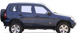
Niva SUV is known as the VAZ-2121
(VAZ 21213, VAZ 21214) and since 2006 as Lada 4×4
.
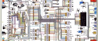
Produced from 1977 to the present with various body modifications, mainly 3- and 5-door station wagons with gasoline engines ( carburetor, injection ). In our publication you will find a description of the fuse and relay blocks of the Niva 2121 with their locations, photo examples of execution and block diagrams. Note the fuse responsible for the cigarette lighter. In conclusion, we will offer a Niva electrical diagram for downloading.
Due to the long production period and the huge variety of designs, there is no one general description of the fuse and relay block for Niva 2121. In your car, the purpose of the fuses may differ from those presented.
All main fuse and relay boxes are located in the passenger compartment, under the instrument panel on the driver's side.
VAZ error table
If replacing the fuel does not help, it is necessary to diagnose the air intake system. It is necessary to tighten the fastening clamps, change the air filter element and check the pressure in the rail (the normalized indicator is no more than 2.8 atm). It is also necessary to perform diagnostics:
Diagnostics of high-voltage wires is carried out using a tester; it is necessary to check the resistance. If the obtained value is more than 10 kOhm, then the cables must be replaced. You also need to check the integrity of the spark plugs and make sure that there is no carbon deposits on their tips. If the described actions did not help determine the cause, the cylinders are diagnosed. The user needs to check the compression level, which should be approximately the same in each device. If the obtained values differ by more than 0.5 atm, then the power unit needs to be tested in more detail.
Replacing oxygen concentration sensors
Oxygen sensors need to be replaced after 75 thousand km of vehicle mileage.
We unscrew the sensors when the engine has cooled down.
Disconnect the negative terminal of the battery.
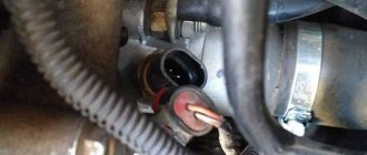
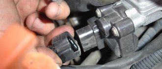
To replace the control sensor, in the engine compartment, press the lock of the wire block and disconnect it
Disconnect the plastic holder of the sensor wiring harness from the bracket
Use a 22 key to unscrew the sensor.
We remove the sensor from the engine compartment
If the sensor is very stuck and cannot be unscrewed using an open-end wrench, then if you are replacing the sensor, you can cut the sensor wires with side cutters and unscrew them with a spanner.
You can also disassemble the wiring block if the sensor cannot be replaced.
To replace the diagnostic oxygen sensor, pry from the bottom of the car with a screwdriver and disconnect the wire holder from the protective casing of the wire blocks.
Using a 10mm wrench, unscrew the two nuts.
Remove the protective casing with wire blocks
We remove the wire blocks from the protective casing
We press the block clamp, disconnect the wiring harness blocks
Use a 22 key to unscrew the sensor.
Removing the diagnostic sensor
Oxygen concentration sensor
When installing the sensor, do not allow dirt and grease to get on the pads and the sensor itself.
We install the sensors in reverse order.
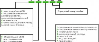
What does the error consist of?
The first character means:
The second character in the code means:
The third character identifies the system in which the problem is detected:
The last two characters are a number that corresponds to the error number in the OBD system.
When malfunctions occur in the operation of the engine or other systems, the “Check Engine” indicator is always on on the VAZ dashboard. Its presence may be due not only to a malfunction of the power unit, but also to problems with the wiring or poor contact of one of the sensors.
Car diagnostics
Diagnostics of the engine and other systems and units in Chevrolet Niva, Cobalt, Lacetti, Lanos, Captiva, Cruze, Aveo 2004, 2005, 2010, 2012 and other model years allows you to timely identify the fault. Thanks to this, the car owner can prevent more serious damage. The errors themselves when diagnosing with a laptop or on a VDO display or other factory dashboard will be different. In the first case, the car owner receives the most accurate information about breakdowns, which allows them to correctly decipher and remove faults. Error combinations will be four-digit.
During self-diagnosis on the on-board computer State on the instrument panel of a VAZ 2123 or Chevrolet Tahoe, Orlando, Blazer, Lanos, Niva, Lacetti, Cruz, Captiva, Epica, Aveo in the T250 and T300 body, faults are displayed in two-digit form. Instead of combinations, messages may appear on the display to warn motorists.
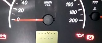
Pressing the odometer button on the dashboard
How to do it yourself?
There are two ways to check for errors in a Chevrolet: self-diagnosis or using additional equipment or a computer. In order for the on-board computer to test for faults, you need to hold down the button on the odometer to reset the daily mileage and turn the key in the ignition. This will cause the needles on the speedometer and gauges to start moving along the scales. And when you press the button again, the ECU will display a message on the display about the version of the firmware being used. After the next press, combinations of problems, if any, will appear on the screen.
Chevrolet Niva error codes: decoding and description of meanings
The popular Russian-made model is very widespread in the CIS countries due to its optimal cost and increased cross-country ability, which is critically important in the conditions of domestic operation. Motorists buy cars for off-road travel and small towns, where the quality of roads leaves much to be desired.
The disadvantages of the car include weak wiring - when the load increases to the design limit, on-board electronic systems often fail, which causes software failures. Chevy Niva error codes appear on the dashboard display or are detected using special equipment, but the common thing is that they all indicate a malfunction of a specific component.
Lambda decoy
The sensor itself often fails and is quite expensive. For this reason, some motorists install the so-called DK blende into the system.
There are two ways to eliminate the problem of a constantly “jamming” lambda - mechanical and electronic. Both methods are good in certain conditions.
Mechanical "trick"
A metal tube is welded onto the sensitive area of the sensor, reducing airflow to the sensor. Consequently, the device thinks that less oxygen is coming in and the system is stabilizing.
The downside of the modification is its low efficiency. The device works stably only on old-style machines where the sensitivity of the electronics is not high.
Electric "trick"
To complete such a system, experts suggest increasing the resistance of the device by soldering an additional part into the sensor circuit. The photo shows a drawing of how this is done.
What and how can you check the lambda?
Catalytic converter overheating. If the lambda is faulty, an incorrect signal is sent to the ECU. This may cause the catalyst to malfunction. It overheats until it turns red and fails.
Indirect signs of sensor malfunctions are unstable operation at low speeds, increased fuel consumption and low dynamics. It must be remembered that these external signs accompany malfunctions of the injection system and malfunctions of the ignition system.
As a result of a failed sensor, the quality of the fuel mixture entering the combustion chamber deteriorates, which disrupts the smooth operation of the engine.
If you find it difficult to determine the malfunction of the exhaust system of your car, then the best way to solve the problem is to contact a car service center in Nagorny to identify the malfunction and repair the exhaust system of your car.
How to replace fuses on a VAZ 21213 (carburetor)?
The block is a metal board with flag-type disposable electrical fuses installed in it. A special fuse is provided for each electrical circuit and for all electrical appliances.
Fuse box
An electrical fuse is a low-melting wire core with two mounting legs enclosed in a plastic sheath. The shells are made of plastic of different colors. There is a marking on the top indicating the rating for which the fuse is designed.
In the event of a sudden surge in voltage, the thin wire instantly burns out and the circuit opens, thereby protecting the corresponding equipment from failure.
Chevrolet Niva error diagnosis
The most reliable way to identify what is wrong with a car is to diagnose electrical appliances and equipment. The procedure allows you to accurately identify breakdowns and quickly repair your car.
There are two ways to detect a problem in a car.
Self-diagnosis VAZ 2123
The simplest procedure allows the motorist to independently identify the damaged area and repair the damage. Thanks to the successful firmware of the on-board computer, some errors are displayed on the standard display. In this case, nothing happens on its own - you will need to perform several steps manually:
If the manipulations are correct, one of the indicated codes will appear on the display, and each Niva Chevrolet error number will be responsible for its own section of the highway:
At the same time, you need to accurately understand that, for example, when error 10 is on the display, the Chevrolet Niva tells the driver that there are several problems (standard, unambiguous codes are summed up).
You should also know that Niva Chevrolet self-diagnosis errors do not reflect the exact location of the breakdown. Codings can only show the section of the wiring where you need to look for the cause of the malfunction. Also, these encryptions may be the result of a software failure after an unsuccessful wash or disconnection of the battery. To obtain more accurate data, the user needs to connect a special diagnostic scanner.
Self-diagnosis
Without going into details of the operation of all electronics, we note that the functioning of all vehicle systems is “monitored” by an electronic control unit (ECU).
It receives information from numerous sensors. Like any computer, the ECU requires software called firmware. This firmware is capable of analyzing indicators received from sensors, comparing them with normal parameters, identifying errors and storing these errors in memory.
Carrying out self-diagnosis
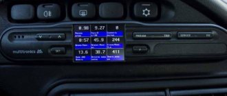
In the Chevrolet Niva, as in some other cars of the VAZ family, some parameters can be displayed on the VDO dashboard. It is often called an integrated on-board computer.
Testing is started by first pressing the daily mileage reset button and simultaneously turning the ignition key.
All instrument needles begin to move, which indicates the beginning of the testing process. Pressing the same button once will cause the firmware version to appear on the display, and pressing it again will give us a reading called an error code.
Panel codes should not be confused with ECU codes, which are diagnosed by external devices.
The operation of the on-board computer cannot be called flawless, since many errors arise as a result of software failure. You have to reset the errors by holding down the daily mileage reset button in testing mode. This diagnostic method is not entirely convenient for the reason that the error code can be the result of the sum of two codes at the same time (10=8+2).
Diagnostics using third-party equipment
More precisely, errors on Chevy Niva can be identified by connecting additional equipment. The technique is more technically complex, but allows us to determine the cause of a breakdown or failure with minimal error. In this case, the sequence of actions is as follows:
If all actions are performed correctly, all available information and any errors in the form of encrypted codes will be displayed in the desktop window.
There are also specialized scanners designed specifically for Chevrolet NIVA. Dealer devices are connected to the place of the standard signaling unit through an output cable.
Separately, we should highlight modern devices designed to connect a smartphone to a car, while reading encodings and controlling operating modes occurs directly from the gadget’s display.
At the same time, you should know what the encodings displayed during diagnostics mean. The code consists of several elements.
The next element is a single digit:
The following digit determines the exact serial number of the line in which the defect was detected:
Fault codes
(Also some codes are presented here)
DIAGNOSTIC CODES FOR CONTROLLER M 7.9.7
| Code | Description |
| P0102 | Mass Air Flow Sensor Circuit Low Signal |
| P0103 | Mass Air Flow Sensor Circuit High Signal |
| P0112 | Intake Air Temperature Sensor Circuit Low Signal |
| P0113 | Intake Air Temperature Sensor Circuit High Signal |
| P0116 | Coolant temperature sensor circuit, signal out of range |
| P0117 | Coolant Temperature Sensor Circuit Low Signal |
| P0118 | Coolant Temperature Sensor Circuit High |
| P0122 | Throttle Position Sensor Circuit Low Signal |
| P0123 | Throttle Position Sensor Circuit High |
| P0130 | The oxygen sensor before the converter is faulty |
| P0131 | Oxygen sensor circuit to converter, low output level |
| P0132 | Oxygen sensor circuit to converter, high output signal level |
| P0133 | Oxygen sensor circuit to the converter, slow response to changes in mixture composition |
| P0134 | The oxygen sensor circuit to the converter is inactive |
| P0135 | The oxygen sensor after the converter is faulty |
| P0136 | The oxygen sensor after the converter is faulty |
| P0137 | Oxygen sensor circuit after the converter, low signal level |
| P0138 | Oxygen sensor circuit after the converter, high signal level |
| P0140 | The oxygen sensor circuit after the converter is inactive |
| P0141 | Oxygen sensor after converter, heater faulty |
| P0171 | Fuel system too lean |
| P0172 | Fuel system too rich |
| P0201 P0202 P0203 P0204 | Cylinder 1 injector (2,3,4), control target break |
| P0261 P0264 P0267 P0270 | Cylinder 1 injector (2,3,4), control target short to ground |
| P0262 P0265 P0271 | Cylinder 1 injector (2,3,4), control circuit shorted to on-board network |
| P0300 | Random/multiple misfires detected |
| P0301 P0302 P0303 P0304 | Cylinder 1 (2,3,4), misfire detected |
| P0327 | Knock Sensor Circuit Low Signal |
| P0328 | Knock Sensor Circuit High Signal |
| P0335 | Crankshaft position sensor circuit is faulty |
| P0336 | Crankshaft position sensor circuit, signal out of range |
| P0340 | Camshaft position sensor is faulty |
| P0342 | Camshaft Position Sensor Circuit Low Signal |
| P0343 | Camshaft Position Sensor Circuit High Signal |
| P0422 | Neutralizer efficiency below threshold |
| P0441 | Gasoline vapor recovery systems, incorrect air flow through the canister purge valve |
| P0480 | Fan relay 1 control circuit faulty |
| P0600 | Vehicle speed sensor is faulty |
| P0606 | Idle system, low engine speed |
| P0507 | Idle system, high engine speed |
| P0560 | On-board network voltage is below the system operability threshold |
| P0562 | On-board voltage, low level |
| P0663 | On-board voltage, high level |
| P0601 | ECM checksum error |
| P0615 | Additional starter relay, control circuit open |
| P0616 | Additional starter relay, control circuit short to ground |
| P0617 | Additional starter relay, control circuit closed to on-board network |
| P1135 | Oxygen sensor preheater, control circuit faulty |
| P1141 | Oxygen sensor heater after converter, control circuit faulty |
| P1386 | ECM knock detection channel error |
| P1410 | Canister purge valve, control circuit shorted to on-board network |
| P1425 | Canister purge valve, control circuit short to ground |
| P1426 | Canister purge valve, control circuit open |
| P1501 | Fuel pump relay, control circuit short to ground |
| P1502 | Fuel pump relay, control circuit shorted to on-board network |
| P1513 | Idle speed control, control circuit short to ground |
| P1514 | Idle air control control circuit faulty |
| P1541 | Fuel pump switch, control circuit open |
| P1570 | Immobilizer, circuit faulty |
| P1602 | HUD controller loss of supply voltage |
| P1606 | Rough road sensor circuit, signal out of acceptable range |
| P1616 | Rough Road Sensor Circuit Low Signal |
| P1617 | Rough Road Sensor Circuit High Signal |
| P1640 | ECM EEPROM read-write error |