Table with errors
A complete list of faults with explanations and recommendations for troubleshooting:
| Error | Sensor malfunctions |
| P0030 | Code P0030 (0030) indicates a malfunction of the oxygen control controller. The problem was detected by the engine control unit as a result of driver diagnostics. To fix the problem, you need to check the electrical circuit of the heating element for a break. |
| P0032 | Code P0032 indicates a short circuit in the control circuit of the heating element of the lambda probe to the on-board network |
| P0036 | Combination P0036 (0036) appears as a result of a malfunction in the electrical circuit that supplies the heating element of the oxygen controller. This refers to a sensor installed after the neutralizer device. The error indicates an open circuit, so first of all you need to check its integrity. |
| P0102 | Code P0102 (0102) indicates a malfunction of the mass air flow controller. The cause of the malfunction is damage to the flow meter wiring. The error may be intermittent, so to fix it, you need to try cleaning or replacing the air filter. The cause of the problem may be damage to the wiring on the microprocessor module connector. To check the flow meter, perform the following steps:
|
| P0103 | The control unit has detected an incorrect signal coming from the mass air flow sensor. Electrical circuit diagnostics required. |
| P0112 | Code 0112 indicates problems with the incoming air temperature controller. It is necessary to check the operation of the sensor, as well as its wiring. |
| P0113 | Code P0113 (0113) appears as a result of incorrect operation of the incoming air temperature controller |
| P0116 | Combination 0116 is associated with an incorrect signal coming from the coolant temperature sensor. The reason may lie directly in the regulator or the integrity of the power line. |
| P0117 | Incorrect signal from antifreeze temperature regulator |
| P0118 | Error P0118 (0118) appears as a result of an increased signal recorded on the refrigerant temperature sensor line |
| P0122 | Code P0122 (0122) is a consequence of an incorrect pulse supplied from the throttle position sensor. There may be interference in the circuit if the line is damaged. |
| P0123 | The microprocessor module has detected that the throttle position controller is sending an incorrect signal. The pulse is out of range. A detailed check of the wiring is required, as the cause may be damage. |
| P0130 | Combination P0130 (0130) appears as a result of damage to the electrical circuit of the control oxygen controller. Possible short circuit of contacts. |
| P0131 | Code 0131 reports low voltage in the electrical circuit of the oxygen control controller |
| P0132 | Combination 0132 indicates an increased voltage signal coming from one of the control oxygen controllers |
| P0133 | Code 0133 literally translates as “diagnosis of a slow response from the control oxygen sensor.” The problems are related to the signal coming from the device. |
| P0134 | Combination P0134 (0134) appears as a result of a decrease in voltage in the electrical circuit of the control lambda probe |
| P0135 | Combination P0135 (0135) is associated with damage to the heater of one of the oxygen controllers. The reason may be a faulty electrical circuit. |
| P0140 | Code 0140 indicates a lack of activity in the power line of the oxygen controller installed after the converter |
| P0222 | Second throttle position sensor voltage too low |
| P0325 | Code P0325 (0325) is associated with an open circuit in the detonation controller |
| P0326 | Code P0326 (0326) appears as a result of the signal supplied from the knock regulator being outside the normal range |
| P0327 | Code P0327 (0327) indicates a reduced signal level coming from the knock controller. It is necessary to check the quality of the sensor's connection to the network. |
| P0328 | Combination P0328 (0328) reports an excess of the signal coming from the engine knock sensor. If the controller is faulty or there is a break in the electrical circuit, the problem may be accompanied by unstable operation of the engine and its random stopping. |
| P0336 | Code 0336 indicates a breakdown of the crankshaft position sensor or damage to its wiring. |
| P0337 | Code 0337 appears as a result of a short to ground in the crankshaft position controller. It is necessary to check the contacts and wiring of the sensor. |
| P0340 | Code P0340 (0340) indicates problems with the camshaft position sensor. The signal coming from the controller does not change in a car with the engine running. If the dashboard shows this error, the user needs to diagnose the sensor electrical circuit. Since the regulator is installed in the engine compartment, the contact on its wiring connector could be clogged. |
| P0341 | Error P0341 (0341) appears as a result of failure or malfunction of the camshaft position sensor |
| P0342 | Code 0342 is associated with a faulty phase sensor. If the controller is faulty, the power unit may detonate during operation. The damaged wire is replaced, and the contacts on the regulator power connector are also cleaned. A failed sensor must also be replaced. |
| P0343 | Code number P0343 (0343) on an 8- or 16-valve Priora with BC (on-board computer) State indicates a fault in the electrical circuit of the phase sensor. The signal coming from the controller is too high. A complete check of the device and its wiring is necessary; perhaps the cause is a short circuit. You may need a multimeter to troubleshoot. |
| P0346 | Malfunction of the phase sensor |
| P0500 | Combination P0500 (0500) appears when the speed controller is not operating correctly. The vehicle speed may be below the threshold. A detailed diagnosis of the signal coming from the regulator is required. |
| P0501 | Error P0501 (0501) indicates an incorrect signal coming from the speed sensor. If the device itself is working and its electrical circuit is intact, then to find the cause, detailed diagnostics of the microprocessor module will be required. |
| P0504 | Code P0504 (0504) appears as a result of a malfunction of the brake pedal controller. The on-board computer diagnoses the mismatch of pulses coming from the devices. Controller signals change inconsistently, which may indicate a malfunction or problems with wiring integrity. Most likely, the cause of the problem is contamination of the contact of the sensor installed on the pedal. |
| P0505 | Code 0505 indicates a malfunction of the idle speed controller. Failure of the regulator can cause a sharp jump in speed. |
| P0511 | Combination P0511 (0511) appears as a result of a malfunction in the idle speed sensor power line. It is necessary to completely check the wiring, test it and diagnose the contacts on the connector. The reason may be that the insulation on the main power cable is worn out. |
| P0830 | Error 0830 indicates a faulty clutch switch. It is necessary to check the operation of the sensor installed directly on the pedal; a wire break or damage to the connector is possible. The problem may be accompanied by increased fuel consumption and failures when shifting gears. |
| P1135 | Code P1135 (1135) The microprocessor module has detected a break or short circuit in the line of the heating element of oxygen sensor 1. The wiring integrity must be checked. |
| P1141 | The error is due to the inoperability of the heating element of the first lambda probe installed after the converter |
| P1513 | Combinations P1513 (1513) appear as a result of a short circuit on the idle speed controller line. Diagnostics of the contacts on the sensor connector is required. |
| P1514 | Code P1514 (1514) appears as a result of an open or short circuit in the wiring of the idle speed sensor. It is necessary to check the integrity of the pins on the block and ring the electrical circuit. A faulty controller must be replaced. |
| P1617 | Code 1617 indicates an increased signal level in the electrical circuit of the rough road controller. In general, this error will not affect the operation of the engine in any way. |
| R2020 | Combination 2022 is associated with a malfunction of the intake shaft flap position controller |
| P2122 | Code P2122 is associated with a reduced signal from the gas pedal position sensor |
| P2127 | The voltage in the electrical circuit of the gas pedal position controller is below the permissible value |
| P2138 | Error P 2138 appears as a result of checking the mismatch of pulses received from two gas pedal controllers. The voltage level in the sensor electrical circuit does not correspond to the standardized value. |
| Code | Engine malfunctions |
| P0101 | Error P0101 (0101) indicates that the air flow readings from the sensor are incorrect. Detailed diagnostics of the controller is required; it may need to be cleaned. |
| P0121 | Open circuit of the third injector. With this problem, the engine may not operate correctly. |
| P0171 | Code P0171 (0171) indicates a malfunction in the fuel supply system. The error appears as a result of a lean combustible mixture. |
| P0172 | Codes P0172 (0172) indicate that the air-fuel mixture is rich. It is necessary to check not only the engine cylinders, but also the elements that influence its formation. This refers to the air filter and flow meter. The cause of the problem may be a lack of tightness. |
| P0204 | If on a VAZ Euro it was possible to read VDO code 0204, this indicates a break in the wiring in the electrical control circuit of the fourth cylinder injector. |
| P0300 | If error P0300 (0300) occurs, the control unit reports that the threshold value for misfire of the air-fuel mixture has been exceeded. It is necessary to accurately check their number. |
| P0301 | Code P0301 (0301) appears as a result of misfire in the first cylinder of the engine |
| P0302 | Misfire in the second cylinder of the power unit. It is necessary to check the operation of the mass air and oxygen flow sensors. |
| P0303 | Code P0303 (0303) indicates detection of misfire in the third cylinder of the engine |
| P0304 | The appearance of error P0304 is also associated with misfires for toxicity. Their number is significantly higher than the nominal threshold. |
| P0335 | Code P0335 (0335) indicates a crankshaft (crankshaft) synchronization error. The first thing to do is check the operation of the crankshaft controller and its wiring. |
| P0363 | Code P0363 (0363) indicates a misfire in one of the engine cylinders. The ECU (electronic control unit) has cut off the fuel supply to the idle cylinders. Possible causes of the problem:
If replacing the fuel does not help, it is necessary to diagnose the air intake system. You should tighten the fastening clamps, change the air filter element and check the pressure in the rail (the normalized value is no more than 2.8 atm). It is also necessary to perform diagnostics:
Diagnostics of high-voltage wires is carried out using a tester; it is necessary to check the resistance. If the obtained value is more than 10 kOhm, then the cables must be replaced. You also need to check the integrity of the spark plugs and make sure there is no carbon deposits on their tips. If the described actions do not help determine the cause, the cylinders are diagnosed. The user needs to check the compression level, which should be approximately the same in each device. If the obtained values differ by more than 0.5 atm, then the power unit needs to be tested in more detail. |
| P0422 | Combination P0422 (0422) indicates a malfunction of the neutralizer device. Literally, the code can be deciphered as “determining the oxygen capacity by comparing the amplitude range of two lambda probes - diagnostic and oxygen.” In other words, the aging coefficient of the neutralizing device is greater than the upper maximum value. It is necessary to check the operation of the sensors and replace them if necessary. The cause of the problem may be poor contact between the controllers and the network. |
| P0441 | Combination P0441 (0441) literally stands for “incorrect response of the idle speed support system, the value is higher or lower than the threshold.” The malfunction indicates problems in the operation of the canister purge valve. It is necessary to diagnose the device and clean it; if this does not help, the mechanism should be replaced. |
| P0443 | Code P0443 (0443) reports a malfunction in the electrical circuit for controlling the adsorber purge valve |
| P0444 | Driver diagnostics showed a break in the electrical line of the canister purge valve |
| P0485 | Malfunction of the engine cooling fan - the voltage level on the line is less than or greater than the threshold value. It is necessary to diagnose the signal coming from the device. The cause of the problem may be oxidation or clogged contacts on the fan power connector. |
| P0506 | Reduced idle speed of the power unit |
| P0507 | Combination P0507 (0507) indicates increased speed of the power unit in the idle system. The cause of the problem may be the sensor or its wiring. |
| P1140 | Combination 1140 literally stands for “measured engine load differs from calculation.” There can be many reasons for this problem, ranging from incorrect compression to malfunctions in the microprocessor module. |
| P1301 | The appearance of error P1301 (1301) is associated with the excess number of misfires to protect the converter. A decrease in quantity may negatively affect the functioning of the latter. |
| P1302 | Code 1302 A large number of misfires in the ignition system to protect the neutralizer device |
| P1303 | A misfire was detected in the third cylinder of the engine, which may affect the operation of the converter. |
| P1304 | Code 1304 appears as a result of misfire in the fourth cylinder of the engine. |
| P1335 | Error P1335 literally stands for “throttle valve actuator control monitoring: position out of range.” Possible causes of the problem:
To fix the problem, you can try to relearn the throttle valve, to do this, perform the following steps:
|
| P1426 | Combination P1426 (1426) indicates a break in the control line of the canister purge valve |
| P1545 | The throttle valve position is outside the operating range. It is necessary to clean the mechanism and adapt it if necessary. It is also necessary to check the connector and damper operating parameters using diagnostic equipment. If these steps do not help resolve the problem, you need to contact specialists to flash the microprocessor module or perform this task yourself. |
| P1578 | Error 1578 can be literally translated as “zero adaptation parameter is out of range.” Possible solutions to the problem:
|
| P1602 | Code P1602 (1602) means a loss of voltage in the power supply circuit. With this problem, the engine often does not start because the starter is not receiving power. The Multitronics computer may be faulty, but first of all you need to check the battery charge. The problem may be due to a broken generator set. |
| P2135 | The appearance of code P2135 (2135) is associated with malfunctions in the functioning of the throttle mechanism. It is necessary to check the sensor and the damper; perhaps it is stuck in the open or closed position. If the node itself is operational, a check of the microprocessor module is required. |
| P2187 | Combination P2187 appears when the air-fuel mixture in the engine cylinders is lean |
| P2188 | With error P2188, the engine control unit reports that the air-fuel mixture is over-rich when the power unit is idling. A detailed diagnosis of the fuel supply system is required. |
| P2304 | Increased current in the electrical circuit of one of the ignition coils |
| Code | Electrical faults |
| P0351 | Code P0351 (0351) appears as a result of a break in the electrical control circuit of the ignition coil of the first cylinder. When this combination appears, the following problems are possible:
|
| P0352 | Broken or damaged ignition coil control wiring installed on the second cylinder |
| P0480 | Combination P0480 indicates an open circuit in the engine cooling fan relay |
| P0560 | Error P0560 (0560) appears due to voltage surges in the vehicle's electrical network |
| P0562 | Combination P0562 (0562) indicates low voltage in the vehicle's electrical network |
| P0563 | Increased voltage in the vehicle's on-board network. It is possible that the car's battery is severely discharged and the generator unit is working in increased mode to compensate for the discharge. Diagnosis of the battery as well as the generator is required. In the latter, the regulator relay may be faulty. |
| P0601 | The appearance of error 0601 is due to a malfunction of the permanent memory module of the motor control unit |
| P0603 | Code P0603 indicates a malfunction of the RAM module in the engine control unit. It is necessary to check the connectors on the main block of the module, as well as diagnose the integrity of the contacts. Reflashing the microprocessor will help eliminate the cause if the problem is non-mechanical in nature. |
| P0615 | Driver diagnostics showed an open circuit in the starter relay |
| P0628 | Code 0628 is associated with a short circuit in the fuel pump relay circuit during driver diagnostics. A detailed check of the wiring is required, as well as the socket in the fuse box. If the fuel pump relay is faulty, the engine will not be able to start. |
| P0650 | Code P0650 indicates a malfunction of the lamp indication circuit |
| P1336 | Code 1336 literally means “the controller type does not match the standard one.” Most likely, the reason is poor contact of the main relay; it is necessary to bend its legs. |
| P1425 | Code 1425 - short circuit to ground in the electrical circuit of the canister purge control valve |
| P1541 | This error is associated with damage to the fuel pump relay control circuit. |
| P1570 | Damage to the immobilizer control circuit. It is necessary to check the cable powering the device; a possible reason may be the antenna. |
| P1600 | No communication with the immobilizer. The problem may not manifest itself in any way in terms of symptoms. |
| P1603 | Malfunction of the internal microprocessor memory module |
| P1612 | Electronic control unit processor memory reset error. Possible signs of problems:
Detailed diagnostics of the microprocessor module and its flashing if necessary are required. |
| P1620 | Combination 1620 indicates a malfunction in the internal memory module of the control unit |
| P1621 | The combination P1621 (1621) indicates a problem with the RAM module. It is necessary to check the microprocessor module for errors. |
| P6060 | Code 6060 indicates a malfunction of the processor device. If the problem is of a software nature, then the problem should be “treated” only by flashing the module. If you do not have the appropriate equipment and skills, you can follow these steps to resolve:
|
| B2AAA | Code B2AAA is a general malfunction of the body control module. There can be many reasons for the problem; most likely, a wire has come loose on one of the connectors. |
| U3FFF | Problems with the engine control unit. The reason may be moisture getting into the wiring supplying the control module. |
| Code | Self-diagnosis errors |
| 1 | Engine control unit malfunction. If, when reading, the module showed this error on a 2110 16 cl or another VAZ, to solve it you need to look at the device block. Most likely, the reason is oxidation of the contacts or damage to the connector. If the control unit malfunctions, the module is flashed. |
| 2 | The voltage in the on-board network is too high. The user needs to check the operation of the battery and generator unit. |
| 3 | Malfunction of the electrical circuit of the fuel level sensor. The device may emit a low or high signal. It is necessary to check the sensor and the electrical circuit that powers it. |
| 4 | Antifreeze controller malfunction. It is necessary to diagnose the sensor and wiring. |
| 5 | External temperature controller error. |
| 6 | Overheating of the power unit. |
| 7 | Emergency engine fluid pressure |
| 8 | The vehicle voltage is too low. Diagnostic steps are similar to the high voltage test. |
| 9 | The battery is discharged (the criterion for triggering the acoustic alarm is met) |
| E | Determining an error in a data packet stored in EEPROM |
| 12 | Malfunctions in the functioning of the diagnostic electrical line of the indicator located on the instrument panel. |
| 13 | The microprocessor module does not receive an impulse from the lambda probe |
| 14 | The control unit detects an increased signal coming from the antifreeze temperature sensor |
| 15 | Coolant temperature controller malfunction. The device outputs a reduced signal that does not correspond to the nominal value. |
| 16 | Increased voltage in the vehicle electrical network |
| 17 | Low voltage in the on-board network |
| 19 | Malfunction of the crankshaft position sensor. An incorrect signal is supplied to the microprocessor module from the controller. It is recommended to diagnose the connector and contacts; it is possible that dirt has got on the block. |
| 21 | Malfunction of the throttle valve position regulator. The problem may be with the node itself. It is recommended to check the operation of the controller and its wiring. |
| 22 | Reduced signal coming from the throttle position controller |
| 23 | The signal coming from the intake air temperature controller is too high |
| 24 | Vehicle speed sensor malfunction. The speedometer may be showing incorrect readings. To fix the problem, you need to check the contacts on the European instrument panel; perhaps the connector is simply coming off. |
| 25 | Too low signal detected in the electrical circuit of the intake air temperature sensor |
| 27, 28 | Incorrect pulse coming from the exhaust gas sensor |
| 33, 34 | Problems with the flow meter. It is necessary to check all contacts and the electrical circuit through which the mass air flow controller is connected. |
| 35 | The microprocessor module has detected a deviation in idle speed, the reason may be a sensor malfunction |
| 41 | Incorrect signal coming from the phase regulator |
| 42 | Damage to the electrical circuit of the electronic ignition system |
| 43 | Incorrect pulse coming from the knock sensor |
| 44, 45 | The mixture in the engine cylinders is too lean or rich |
| 49 | Vacuum leak, requires diagnostics of all lines and tightness check |
| 51, 52 | Malfunction of one of the control unit memory modules - RAM or PROM |
| 53 | The control unit cannot detect the signal coming from the exhaust gas sensor |
| 54 | Lack of impulse supplied from the octane corrector regulator |
| 55 | Leaning of the air-fuel mixture at low load on the car engine |
| 61 | Lambda probe malfunction |
| Code | Three-digit combinations |
| 102 | Malfunction of the mass air flow sensor. A possible cause of the problem may be a clogged device; sometimes cleaning the controller can eliminate it. |
| 131 | One of the oxygen controllers is faulty. A detailed check of all sensors, their contacts, as well as heating devices is required. |
| 134 | No signal from the oxygen controller. The sensor number is not indicated, nor is its location, so you need to check each device. |
| 171 | Lean mixture in the cylinders of the power unit |
| 300 | The microprocessor module detected random or multiple misfires in the engine cylinders |
| 327 | Low level of signal recorded in the electrical control circuit of the detonation controller |
| 328 | The signal detected in the knock sensor control circuit is too high |
| 343 | Malfunction of the camshaft position sensor, increased signal coming from the device |
| 501 | Speed controller malfunction |
| 504 | Incorrect signal coming from the brake pedal adjuster. It is necessary to check the sensor contacts for integrity of the pins and clogging of the connector. |
| 422 | Low efficiency of the catalyst device. The cause of the problem may be a leak in the system. |
| 441 | Incorrect air flow through the canister purge valve. The appearance of this code may be due to the following conditions:
|
| 603 | External RAM module error |
| 830 | Malfunction of the controller installed on the clutch pedal |
| Code | Composite Combinations |
| 3456, 78, 78E | These codes on BC M74 on VAZ 11183 or 212140 mean individual errors, for example 3456 - 3, 4, 5 and 6. |
Decoding of VAZ error codes is presented for the following models:
- 1118 Kalina (Kalina);
- 2104;
- 21041;
- 2105;
- 2107;
- 21074;
- 2109;
- 21093;
- 21099;
- 2110;
- 21102;
- 21103;
- 2111;
- 2112;
- 2113;
- 2114;
- 21114;
- 21124;
- 2115 with engine injector 8 and 16 valves;
- 21150;
- 21154;
- 2131;
- 2170 Priora (Priora);
- 2190 Granta (Grant);
- 2123, 21214, 2131 Niva (Niva);
Self-diagnosis of VAZ 2107 injector with your own hands
Installing an injector in the VAZ 2107 made it possible to significantly improve engine performance. Changing the type of fuel system increases the amount of energy that is produced during the combustion of gasoline. Compared to a carburetor engine, a fuel injection system is more efficient in the initial stages, but over time its performance decreases. What does this depend on?
VAZ 2107 injector plays the role of the final element in the fuel system of the car. The air mixture, together with a cloud of atomized gasoline, creates a huge amount of energy. Over time, this atomization may become less effective, the fuel jets will become weaker, and all due to low-quality gasoline.
The main cause of injector failure is poor fuel. Car fuel consists of many chemical components; in addition, various impurities are added to it, which should improve the overall performance of the engine. This factor cannot be ignored, since such gasoline leaves sediment on the walls of the fuel system. The thinnest channels are in the injectors, and it is these devices that suffer first. VAZ 21074 injector has the same problem. During operation, deposits from fuel only accumulate. What needs to be done to stop this?
How to diagnose the error?
It is important to know
There are two options for diagnosing a VAZ car - testing using the instrument panel and using a computer. The second option is considered more accurate, but its implementation will require a special program and a cable for connecting to the diagnostic connector.
Checking using a computer is done like this:
- The diagnostic wire is connected to the laptop. Its second end must be connected to the OBD2 connector in the Lada car. The location of this block differs depending on the car model; this nuance must be clarified in the service manual.
- A diagnostic program is launched on the computer, which allows you to decipher error codes. To start the test, press the corresponding button.
- The diagnostic process begins. Depending on the utility, the program can separately check the operation of the engine, transmission or electronics.
- After the test is completed, combinations of faults will appear on the computer screen that need to be deciphered. Depending on the program, a description of the error may also be displayed immediately.
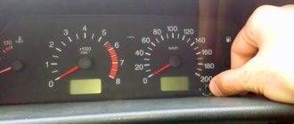
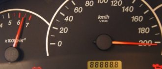
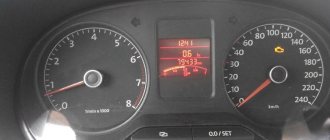
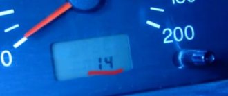
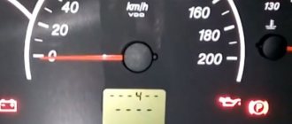
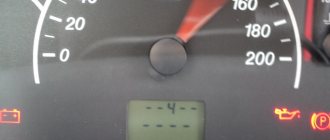
Diagnostics using the dashboard is performed as follows:
- The car owner sits in the driver's seat and presses the daily mileage reset button on the odometer.
- The key is inserted into the lock and scrolled to the “ACC” position.
- The daily mileage reset button is released. The arrows on the speedometer, tachometer, and sensors will begin to quickly move from the minimum position to the maximum.
- The odometer key is pressed and released. An inscription with the software version will be displayed on the instrument cluster screen.
- After the third press of the odometer key, combinations of faults will appear on the screen.
Video: diagnosing a VAZ using the dashboard
The CarFance channel in its video showed in detail the process of testing a Lada car using a control combination.
On-board computer VAZ 2107
An on-board computer is a “smart” digital device that performs certain calculation operations by receiving data from various sensors. That is, the “on-board vehicle” is a device that collects all the necessary information about the “well-being” of the car’s systems and converts it into signs that the driver can understand.
Today, two types of on-board computers are installed on cars of all types:
What kind of ECU is on the VAZ 2107
Initially, the VAZ 2107 was not equipped with on-board devices, so drivers were deprived of the opportunity to obtain operational data on the state of the vehicle systems. However, later versions of the “Seven” with an injection engine are already conducive to installing this device.
Factory models of the VAZ 2107 (injector) were not equipped with an ECU, but had a special socket for the device and connection capabilities.
The injection model of the “seven” has a variety of different electronic components. Any driver knows that sooner or later one of these components may begin to malfunction or fail. At the same time, self-diagnosis of a breakdown in such cases is very difficult - again due to the complexity of the electronic systems of the VAZ 2107. And installing even a standard ECU model will allow you to receive data on breakdowns in a timely manner and quickly fix faults yourself.
Thus, on the VAZ 2107 you can install any standard on-board computer that is suitable in design and connectors:
Main functions of the ECU for VAZ 2107
Any on-board computer installed on a VAZ 2107 must perform the following functions:
Any ECU has a screen and indicators that are inserted into the center console inside the car. On the screen, the driver sees a display of the current performance indicators of the machine and can control certain components.
The on-board computer on the VAZ 2107 is located immediately behind the instrument panel, connecting to the car’s sensors. The screen or indicators are displayed directly on the dashboard for driver convenience.
How to reset the error?
Good to know
You can delete the error code from the memory of the VAZ control unit by disconnecting the terminal from the battery.
The reset procedure is performed as follows:
- The vehicle's ignition system is activated, but the power unit does not start.
- The engine compartment of the vehicle opens. Using a wrench, loosen the screw that secures the terminal clamp on the negative output of the battery.
- After about one minute the contact is reconnected.
- The engine compartment of the car is closed, the ignition system in the car is turned off.
- The car engine is starting. If the “Check” indicator remains lit on the dashboard, it should disappear on its own after a few kilometers.
ECU firmware
Firmware update of the electronic control unit is an opportunity to expand the capabilities of your on-board vehicle and make its operation more efficient. It must be said that the first versions of programs for firmware (or chip tuning) of the VAZ 2107 appeared back in 2008.
For most G7 owners, software chip tuning is simply necessary, since this operation allows:
ECU firmware must be performed exclusively at a service center and after a complete technical inspection of the motor by specialists. Special service equipment is provided for this procedure. Self-firmware can only be performed if you have experience and modern equipment.
Video: how to flash the ECU on a VAZ 2107 yourself
The VAZ 2107 ECU can be considered a device that will allow you to quickly monitor the operation of all vehicle systems and troubleshoot problems in a timely manner. Of course, there is no particular need to install an on-board vehicle on your car: the “seven” already quite satisfactorily fulfills all the obligations assigned to it. However, the ECU helps the driver to notice malfunctions and wear of mechanisms in time and quickly respond to them.
The cost of diagnosing errors for VAZ at service stations in Moscow and St. Petersburg
Approximate prices for computer diagnostics:
| City | Company name | Address | Phone number | Price |
| Moscow | North Motors | St. Dubninskaya, 83 | +7 | 2500 rub. |
| Silver elephant | St. Pyalovskaya, 7 | +7 | 3500 rub. | |
| Saint Petersburg | Automagic | St. Uchitelskaya, 23 | +7 | 2000 rub. |
| ClinliCar | Bolshoy Sampsonievsky Ave., 61k2 | +7 | 3000 rub. |
Correction of internal control programs (chip tuning)
Chip tuning
Chip tuning, like ECM modification, also involves changing the factory settings of the software in order to eliminate certain errors in the operation of the software. But the ultimate goal of chip tuning is somewhat different, and is to significantly increase torque and obtain maximum performance from the engine.
The cost that a car owner has to pay to obtain additional power is quite high. Often, as a result of chip tuning, fuel consumption increases significantly and the life of the internal combustion engine decreases.
Taking into account the above information, every car owner should know the answer to two questions before adjusting the injector:
Basic engine malfunctions
VAZ 2107 cars are equipped with three main types of power units with a displacement of 1.5, 1.6 and 1.7 liters. The second engine is equipped with a distributed injection system, which differs significantly from carburetor engines. During long-term operation, parts and components of the unit are subject to wear, which can cause the following malfunctions:
Diagnosis of injector or ECU malfunctions is carried out using a special tester, which is available at specialized service stations. Repair and restoration work on the engine is classified as complex and requires high qualifications and special skills.
ECU firmware
Firmware update of the electronic control unit is an opportunity to expand the capabilities of your on-board vehicle and make its operation more efficient. It must be said that the first versions of programs for firmware (or chip tuning) of the VAZ 2107 appeared back in 2008.
For most G7 owners, software chip tuning is simply necessary, since this operation allows:
ECU firmware must be performed exclusively at a service center and after a complete technical inspection of the motor by specialists. Special service equipment is provided for this procedure. Self-firmware can only be performed if you have experience and modern equipment.
Video: how to flash the ECU on a VAZ 2107 yourself
The VAZ 2107 ECU can be considered a device that will allow you to quickly monitor the operation of all vehicle systems and troubleshoot problems in a timely manner. Of course, there is no particular need to install an on-board vehicle on your car: the “seven” already quite satisfactorily fulfills all the obligations assigned to it. However, the ECU helps the driver to notice malfunctions and wear of mechanisms in time and quickly respond to them.
Cleaning and preventing plaque in the system
The injector device is very sensitive to large inclusions in gasoline. If you are using a cheap brand of fuel, be prepared to change your injectors soon. So the first thing you should do for your VAZ fuel pump is change the brand of fuel. The power supply system of the VAZ 2107 should become cleaner; the possibility of plaque formation in the system is still not excluded. Since the flammable liquid in the channels occasionally stagnates and sometimes even freezes, an early breakdown can be prevented only in one way - regular cleaning.
Approximately every 35-40 thousand km it is necessary to carry out preventive cleaning work on the fuel system. You need to wash the channels with your own hands. The performance of the engine will depend on the quality of cleaning. If this procedure is carried out irregularly, then soon you can say goodbye to one injector and look for a new one, and then you will have to change the remaining elements of the VAZ fuel pump.
In 4-cylinder types of injection engines, different intensities of injector clogging are observed. The temperature in the area of cylinders 2 and 3 is always elevated, so sediment accumulation occurs there faster.
A special admixture of polyetheramine is considered a prophylactic agent in such cases. It prevents the accumulation of burning for a long time.
Damage diagnostics
How to understand that an injector needs to be replaced, checked or repaired? Even without sensors, you can understand that repair of fuel system elements is required if there are 1 of 2 main signs in models 2107, 21074:
Sometimes it is impossible to determine on your own where the damage is, and only then will diagnostics at service centers come in handy. A blockage can cause quite serious damage to the VAZ 2107 injector, as well as rupture of channels. The pressure that arises inside the system can easily destroy the most fragile parts. Here you won’t be able to fix the situation with your own hands, even if you have a complete diagram of the car at hand. There is only one conclusion - you need to devote a lot of time and attention to cleaning injectors and do it regularly.
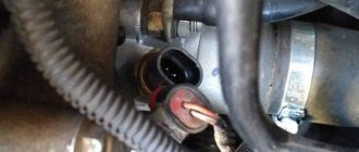
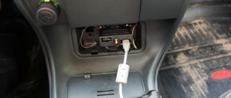
Where is the diagnostic connector located?
The type of device in question, which is also called a diagnostic block, in the design of the 7 and other cars serves to check the condition of the vehicle for errors and malfunctions. After such manipulation, you can decide on the need to repair or replace parts and mechanisms.
Structurally, the connector is a contact connection with a large number of pins. An autonomous source (computer) is connected to this connection, and a test event is carried out using special programs. On the seven, the diagnostic connector is located in the passenger compartment on the passenger side under the glove compartment. By the way, on many car models of domestic and foreign production, the connector is also located in this place.
To connect the computer to the car via the connection, you do not need to disassemble, remove or unscrew anything. The check can be carried out while inside the car, since the essence of this process is to identify errors in the operation of the engine.