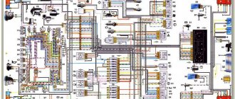
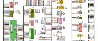
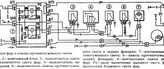
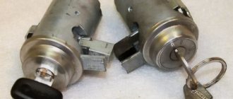
Windshield wiper motor. Headlight switch. Sound signals.
Throttle valve of the first chamber. 3. Charging system - 2 It should be noted that in this case the contact pad has also undergone certain changes. Level indicator and fuel reserve sensor. Necessary Always Enabled Necessary cookies are absolutely essential for the website to function properly.
Differences in wiring As for wiring in cars and others, it can be done in different variations, which makes it easier to maintain the system at home. Those fans of domestic SUVs who were willing to pay such a price could only purchase a car abroad. Front lights.
Rear fog lamp switch. For example, in the case of a carburetor, the electrical circuit for charging the battery and ignition system is not protected, unlike injectors.
Turn signal relay VAZ classic. Testing, diagram, principle of operation.
Circuit breakers
The block of protective devices in Niva is a board on which disposable fuses are installed, containing a fuse inside. Each of them protects one or more electrical circuits from overvoltage.
The unit is located in the cabin on the left side. Protective equipment is numbered. So, 1 is responsible for the work:
- windshield washer;
- stove fan;
- cleaners for all headlights;
- heating, wiper and washer for tailgate glass.
Fuse number 2 controls:
- turn signals, their operation in emergency mode, relay-breaker;
- reversing lamps;
- front windshield wipers;
- dashboard indicators (coolant and oil level, carburetor valve position, parking brake);
- indicators of fuel reserve and antifreeze temperature
3-4 – protect the circuit of the left and right high beams, respectively;
5-6 – low beam.
7 – fuse controls the following elements of the Niva electrical circuit:
- dimensions (rear right and left front);
- license plate illumination.
- lighting of the dashboard, cigarette lighter, interior light switches;
- other marker signals.
9 – the fuse is responsible for:
- turn indicator;
- relay-interrupter and alarm indicator;
- contacts for turning on the rear window heater;
- horn;
- socket;
- interior light;
- rear brake light.
- fog light (rear);
- headlight cleaner motor (start, return to initial position).
16 – is responsible for the operation of the cigarette lighter.
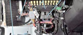
Another block is located in the engine compartment. There fuses are responsible for:
Mounting blocks for Lada 4×4 2020
https://www.youtube.com/watch?v=SqqIBAU8osQ
The turn signal relay (part number 8450082700, 9-pin), as well as the windshield wiper relay, are located under the trim in the driver’s feet, to the left of the fuse mounting block.
Read news about the new Niva
- Diagram and location of the fuse box Niva VAZ-21213 and 21214
- Diagram and location of the fuse box Niva VAZ-21213 and 21214
- Front lower suspension arms VAZ-2121 - Drawings, 3D Models, Projects, Cars and automotive industry (Car service)
- Timing marks on a Chevrolet Niva car
- Chassis, front suspension, device, Design, operation, description, device, car repair Niva VAZ 2121, engine, assembly, disassembly, transmission, gearbox
- Suspension lift in the field yourself | Niva Repair
- Niva 2121 suspension lift do-it-yourself drawings
- Tuning Niva 2121 with your own hands: body, interior, suspension
Dashboard
All control devices are interconnected. This combination consists in particular of:
- speedometer;
- tachometer;
- coolant temperature indicator;
- 12 indicator lamps;
- battery charge sensor;
- fuel level indicator.
All of them are located on the panel.
The schematic diagram shows the combinations available on the instrument panel:
- tachometer (1);
- stabilizer (2);
- panel illumination (3);
- coolant heating indicator (4);
- gasoline level (5);
- toxicity reduction systems (6);
- heated luggage door glass (7);
- fog lights (8);
- high beam (9);
- outdoor lighting (10);
- turn signals (11);
- TG level (13);
- oil pressure (14);
- differential locks (15);
- fuel reserve (16);
- seat belts (17);
- parking brake (18).
D1, D2 are diodes (type IN4002).
Cars manufactured before 1996 also have a voltmeter (12 in the diagram).
Finally, there are two resistors:
- R1 – at 470 Ohm (0.25 W);
- R2 –51 Ohm, (5 W).
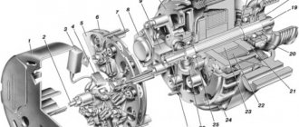
Characteristics of the standard generator
The main characteristics of the generator installed by the manufacturer in Niva 21214, 21213, 2121 will be considered using the example of generator type 9412.3701:
- current – 80A;
- voltage – 13.2 V,
- rotation is right.
The cost of standard models of electric generators is 5-7 thousand rubles. If the unit breaks down, it is possible to replace its components or completely replace it with the original or analogues. The prices of the most common ones are presented in the table.
| Analogue | vendor code | Cost, in rubles |
| Generator VAZ-2104-21073,21214 | 9412.3701-03 | 5900 |
| Generator VAZ-2104-21073,21214 | 372.3701-03/05 | 3800 |
| Generator VAZ 2121-21213,21214 | 9412.3701 | 5450 |
The table shows that in the process of replacing a generator on a Niva, you can give preference to a cheaper universal analogue.
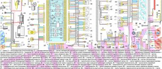
24.4. Interactive diagram of electrical equipment of VAZ-21213 cars
1 — front lights; 2 – side direction indicators; 3 — electric motor for windshield washer; 4 — headlight washer motor*; 5 - switch; 6 – battery; 7 - starter; 8 – generator; 9 — headlights; 10 – gearmotors for headlight cleaners*; 11 – sound signal; 12 – spark plugs; 13 — carburetor limit switch; 14 — carburetor solenoid valve; 15 — ignition coil; 16 — windshield wiper gearmotor; 17 – carburetor solenoid valve control unit; 18 — ignition distributor sensor; 19 – coolant temperature indicator sensor; 20 – oil pressure warning lamp sensor; 21 – plug socket for a portable lamp**; 22 – brake fluid level warning lamp sensor; 23 – windshield wiper relay; 24 – relay for turning on the rear fog light***; 25 – relay for turning on the heated rear window; 26 – relay for turning on headlight cleaners and washer*; 27 – relay for turning on low beam headlights; 28 — relay for turning on the high beam headlights; 29 — ignition relay; 30 – starter activation relay; 31 — relay-breaker for alarm and direction indicators; 32 — heater electric motor;
33 – additional resistor of the heater electric motor; 34 – backlight lamps for heater control levers; 35 – external lighting switch; 36 – main fuse block; 37 – additional fuse block; 38 – reverse light switch; 39 – brake light switch; 40 – instrument lighting regulator; 41 – ignition switch; 42 – three-lever switch; 43 – alarm switch; 44 – tailgate glass cleaner and washer switch*; 45 – heater motor switch; 46 – switch for heating the rear door glass; 47 – rear fog light switch; 48 – lamp switches located in the door pillars; 49 – interior lamps; 50 – cigarette lighter; 51 – switch for the warning lamp for closing the carburetor air damper; 52 – control lamp for covering the carburetor air damper; 53 – switch for the differential lock warning lamp; 54 – parking brake warning lamp switch; 55 – sensor for level indicator and fuel reserve; 56 – instrument cluster; 57 – tailgate glass washer motor; 58 – rear lights; 59 – block for connecting additional brake lights; 60 – blocks for connecting side marker indicators; 61 – pads for connecting to the heated glass element of the tailgate; 62 – license plate lights; 63 – rear door glass wiper motor.
The order of conditional numbering of plugs in blocks:
a – windshield wipers, headlights and tailgate glass, windshield wiper relay breaker; b — ignition distributor sensor; c – relay-interrupter for alarm and direction indicators; g - switch; d — three-lever switch; e — alarm switch; g – relay for turning on the rear fog light; h — rear lights (numbering of terminals in order from top to bottom); and – instrument clusters.
In the instrument panel wiring harness, the second ends of the white wires are brought together to one point, which is connected to the instrument lighting control. The second ends of the black wires are also brought together to a point connected to ground. The second ends of the yellow wires with a blue stripe are brought together to a point connected to terminal “A” of the main fuse block. And the second ends of the orange wires are also brought together to a point connected to terminal “B” of the main fuse block.
* Installed on parts of manufactured cars; **not installed since 2000; *** installed since 2001. Previously, the rear fog light was switched on directly by switch 47, powered by fuse 3 of the additional fuse box.
This is interesting: Decoking of piston rings with dimexide
Generator faults
During the operation of any car, unpleasant situations often arise in the form of failure of one or another element. Niva is no exception, and most often the generator suffers.
If the generator seems to be faulty, it is recommended to check its functionality using a multimeter. To do this, you will need to start the engine and check the voltage at the battery terminals. The standard value that a multimeter should read is 13.6 V.
If the readings during measurement are higher, it means that a break or short circuit in the windings has occurred in the structure. The same can be said about the case when the voltage is below the specified number. This procedure is carried out regardless of the engine: injector or carburetor.
Also, if the breakdown is caused by another reason, you can replace the generator itself. Usually, for replacement, they turn to special service stations, but if necessary, the work can be done with your own hands.
Wiring diagram VAZ 21213 carburetor
How to use the interactive wiring diagram
If you hover your mouse over the greenish circle located next to a diagram element, the name of the element pops up.
To see which pins are connected, click on the slightly shaded rectangular area near the end of the wire or where the wire meets the connector it is connected to, which will animate the wire according to the current flowing through it. The mouse pointer changes appearance when hovering over such an area. To turn off the animation, click again.
To enlarge the image, right-click and select the “enlarge” menu item. To return the image to its original scale, select the “show all” menu item.
Electrical circuit elements
01 - front right lamp 02 - front left lamp 03 - side right turn signal 04 - left side turn signal 05 - windshield washer motor 06 - headlight washer motor 07 - switch 08 - battery 09 - starter 10 - generator 11 - right headlight 12 — left headlight 13 — right headlight cleaner gearmotor 14 — left headlight cleaner gearmotor 15 — sound signal 16 — spark plugs 17 — carburetor limit switch 18 — carburetor solenoid valve 19 — ignition coil 20 — windshield wiper gearmotor 21 — solenoid valve control unit carburetor 22 - ignition distributor sensor 23 - coolant temperature sensor 24 - insufficient oil pressure sensor 25 - portable lamp socket 26 - insufficient brake fluid level sensor 27 - windshield wiper relay breaker 28 - rear fog light lamp relay 29 - rear heating relay glass 30 — relay for headlight cleaners and washer 31 — low beam headlight relay 32 — high beam headlight relay 33 — starter relay 34 — hazard warning and turn signal relay breaker 35 — ignition relay 36 — heater electric motor 37 — additional resistor for heater electric motor 38 — illumination lamp for heater control levers 39 — switch for exterior lighting lamps 40 — main fuse block 41 — additional fuse block 42 — reverse light switch 43 — brake light switch. 44 - instrument dimmer switch 45 - ignition switch 46 - three-lever steering column switch 47 - hazard warning switch 48 - switch for headlight cleaners and washers 49 - heater motor switch 50 - rear window heating switch 51 - rear fog light switch 52 - light limit switch interior 53 — interior lamp 54 — cigarette lighter 55 — carburetor choke closed indicator lamp switch 56 — carburetor choke closed indicator lamp 57 — differential lock indication switch 58 — parking brake indication switch 59 — fuel level and fuel reserve indicator sensor 60 — instrument cluster 61 — rear window washer electric motor 62 — rear right light 63 — rear left light 64 — connector for additional brake lights 65 — connectors for connecting additional side lights 66 — connector for connecting to the rear window heating element 67 — license plate lights 68 — rear wiper motor
Generator replacement
To repair or replace the generator, the car owner will have to remove the unit completely from the car or turn to professionals for work. If you still want to carry out the replacement yourself, then first you will need to prepare all the necessary tools:
- hammer;
- extension;
- keys to "10" and "19".
The procedure consists of the following sequence of actions:
- First, you will need to park the car in a place designated for inspection and repair. The car will also need to be secured using special wheel chocks. Finally, in order for the work to be carried out safely, you should disconnect the battery by disconnecting the terminals from it.
- After this, you need to remove the engine protection. It is attached to several bolts, and they must be unscrewed to get to the lowest bolt of the generator.
- After this, you will need to knock out the mounting bolt using a hammer. It is recommended to knock carefully so as not to damage the thread and to prevent the bolt from coming out in the opposite direction. A hammer is necessary, since a wrench or any other tool simply cannot handle a bolt.
- Next, you need to remove the bolt, swinging the generator from side to side. It is necessary to bolt in any case, as this makes it easier to remove the rod.
- The fourth step involves disconnecting the wiring. To do this, the power wires connected to the housing are disconnected from the unit. In this case, you can first disconnect the plug from the wires.
- Wires are also attached to the generator, tightened with a nut or bracket. In this case, the nuts must be unscrewed with a wrench, and then the loose wires must be pulled out.
- Finally, after disconnecting the wires, you can begin to unscrew the upper fastening element with the belt tensioner. For this you will also need a wrench, as well as a small extension cord.
- Disconnecting the fastener will allow you to remove the belt and alternator. Then you can start cleaning the vacated space with a brush and installing a new unit.
The structure is assembled in the reverse order; the entire procedure will take about two hours if you have all the necessary tools.
Additionally, it is worth noting that when everything is assembled, you will need to adjust the position of the generator using the tensioner. To do this, you need to unscrew the tensioner nut and tighten or loosen the belt, while observing the battery charge.
Also interesting: Standard-type Chevrolet Niva car alarm
If the indicator returns to normal, then the selected tension is sufficient. There is no need to tighten the structure, as the generator bearing may fail. If the tension is insufficient, the generator will work intermittently, and this can also lead to breakdown.
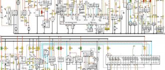
Electrical diagram of VAZ-21213
1. Front lights.2. Side direction indicators.3. Windshield washer motor.4. Headlight washer motor*.5. Switch.6. Rechargeable battery.7. Starter VAZ-21213.8. Generator.9. Headlights.10. Geared motors for headlight cleaners*.11. Sound signal.12. Spark plugs.13. Carburetor limit switch.14. Carburetor solenoid valve.15. Ignition coil.16. Windshield wiper motor gearbox.17. Carburetor solenoid valve control unit.18. Ignition distributor sensor.19. Coolant temperature indicator sensor.20. Insufficient oil pressure indicator sensor.21. Portable lamp socket**.22. Insufficient brake fluid level indicator sensor.23. Windshield wiper relay-breaker.24. Relay for turning on rear fog light lamps***.25. Relay for turning on the rear window heating element.26. Relay for turning on the headlight cleaners and washer*.27. Relay for turning on low beam headlights.28. Headlight high beam relay.30. Starter activation relay.31. Relay-breaker for hazard warning lights and direction indicators.32. Heater electric motor.33. Additional resistor for heater electric motor.34. Illumination lamps for heater control levers.35. External lighting lamp switch.36. Main fuse block.37. Additional fuse block.38. Reversing light switch.39. Brake light switch.40. Regulator for instrument lighting lamps.41. Ignition switch.42. Three-lever switch.43. Hazard switch.44. Switch for headlight cleaners and washers.45. Heater motor switch.46. Rear window heating element switch.47. Rear fog light switch.48. Lamp switches located in the door pillars.49. Interior lighting lamps.50. Cigarette lighter VAZ-21213.51. Switch for the carburetor choke indicator lamp.52. Indicator lamp for closing the carburetor air damper.53. Switch for the differential lock indicator lamp.54. Parking brake indicator lamp switch.55. Level indicator and fuel reserve sensor.56. Instrument cluster.57. Rear window washer motor.58. Tail lights.59. Block for connecting additional brake lights.60. Blocks for connecting side marker indicators.61. Pads for connecting to the rear window heating element.62. License plate lights.63. Rear window wiper motor.
The order of conventional numbering in the blocks: A - headlight and rear window windshield wipers, windshield wiper relay breaker; B — ignition distributor sensor; B — relay-interrupter for alarm and direction indicators; G - switch; D — three-lever switch; E - hazard warning switch; F - relay for turning on the rear fog light lamps; Z — rear lights; And - instrument clusters of VAZ-21213.
In the instrument panel wiring harness, the second ends of the white wires are brought together to one point, which is connected to the instrument lighting control. The second ends of the black wires are also brought together to a point connected to ground. The second ends of the yellow wires with a blue stripe are brought together to a point connected to terminal “A” of the main fuse block. And the second ends of the orange wires are also brought together to a point connected to terminal “B” of the main fuse block.
Sound signal
Procedure for checking the Niva 2121 carburetor valve control system, electrical diagram of Niva 2131, VAZ 2121
Diagnostics of electrical circuits of the Niva 2121 car. Instructions for repairing electrical equipment: generator, starter. Niva 2131 car diagram.
Sound signal activation circuit
1 – plug socket for a portable lamp; 2 – sound signal; 3 – sound signal switch; 4 – fuse block.
Sound signal Niva 2121 - type S-308 or S-309. It is secured in the engine compartment on a bracket to the radiator frame panel. It is turned on by the central button of the car's steering wheel. The contact ring of the switch is attached to the steering wheel, and the spring-loaded contacts are on the connector of the VAZ 2131 steering column switch. If the signal sound becomes weak and hoarse, adjust it by turning the screw on the housing in one direction or another.
The second version of the NIVA 21213 scheme
1. Headlights 2. Headlights 3. Headlight wiper motors 4. Horn 5. Headlight washer motor 6. Windshield washer motor 7. Generator 8. Side turn signals 9. Battery 10. Heater motor 11. Additional heater motor resistor 12 Windshield wiper breaker relay 13. Starter 14. Windshield wiper motor 15. Carburetor limit switch 16. Carburetor solenoid valve 17. Carburetor solenoid valve control unit 18. Switch 19. Spark plugs 20. Ignition distributor sensor 21. Control sensor oil pressure lamps 22. Temperature indicator sensor 23. Socket for a portable lamp 24. Ignition coil 25. Brake fluid level warning lamp sensor 26. Relay for turning on the headlight cleaners and washer 27. Relay for turning on the heated rear window 28. Relay for turning on the high beam headlights 29 . Headlight low beam relay 30. Ignition on relay 31. Starter on relay 32. Differential lock warning lamp switch 33. Exterior lighting switch 34. Cigarette lighter 35. Brake light switch 36. Reverse light switch 37. Turn signal breaker relay and alarm 38. Main fuse block 39. Additional fuse block 40. Illumination lamps for heater control levers, 41. Rear fog light switch 42. Rear window heating switch 43. Heater motor switch 44. Rear window wiper and washer switch 45. Emergency switch alarm 46. Ignition switch 47. Carburetor choke warning lamp 48. Instrument lighting switch 49. Steering column three-lever switch 50. Carburetor choke warning lamp switch 51. Rear window washer motor 52. Courtesy lamp switches located in the door pillars 53. Interior lamps 54. Instrument cluster 55. License plate lights 56. Parking brake warning lamp switch 57. Level indicator and fuel reserve sensor 58. Tail lights 59. Rear window wiper motor 60. Rear window heating element 21213.
This is interesting: What is the difference between air conditioning and climate control?
Additional schemes
Diagram for switching on direction indicators and hazard warning lights
1 — direction indicator lamps in the front lights; 2 — side direction indicators; 3 — ignition switch; 4 - ignition relay; 5 — fuse block VAZ-21213; 6 — direction indicator lamps in the rear lights; 7 - control pump for direction indicators in the instrument cluster; 8 — relay-switch for direction indicators and hazard warning lights; 9 — alarm switch; 10 — direction indicator switch.
External lighting switching diagram
1 — side light lamps in the front lights; 2 - fuse block; 3 — external lighting switch; 4 — instrument lighting switch; 5 - indicator lamp for external lighting in the instrument cluster; 6 — license plate lights; 7 — side light lamps in the rear lights; A - to the lighting lamps of the instrument cluster, switches and backlight display of the VAZ-21213.
Connection diagram for carburetor solenoid valve control system
1 — ignition switch VAZ-21213; 2 - ignition relay; 3 - ignition coil; 4 — control unit; 5 - solenoid valve; 6 — carburetor limit switch.
Engine Control Relay Box
1 — engine control system fuse box;
2 — windshield wiper relay; 3 — fuse blocks; 4 — relay block of the engine control system. The fourth relay block is located above the gas pedal.
| №1 | Ignition relay |
| №2 | Main relay |
| №3 | Right cooling fan relay |
| №4 | Left cooling fan relay |
| №5 | Fuel pump relay (fuel) |
| №6 | Fuel pump fuse F5, 15A |
On some vehicle versions, a starter relay may be located under the additional unit next to the ignition relay.
| №1 | Rear fog lamp relay |
| №2 | Rear window heating relay |
| №3 | Low beam relay |
| №4 | High beam relay |

