The first thing that catches your eye is the absence of a distributor and carburetor. It is quite possible that the reason lies in the distributor or spark plugs. VAZs were equipped with 6ST type batteries. The car generator is designed to provide electric current to the vehicle's on-board network, as well as charge the battery when the power unit is running. In this case, an electromotive force is generated in the generator stator, inducing an alternating current. A small KB image with a resolution of pixel high and pixel wide will allow you to carefully examine all the necessary components and parts, and will also greatly help when repairing electrical equipment on a VAZ. ELECTRICAL DIAGRAM VAZ 2107 CONNECTION OF “37” GENERATOR
These contacts were connected to the central electrodes of the spark plugs via high voltage wires. Knowledge of electrical circuit diagrams will be useful when independently diagnosing problems and repairing a car.
This is the path the voltage passed from the battery to the spark plugs.
A serious difference between the injection version of the VAZ is the presence of an electric fuel pump, which provides high pressure in the gas line necessary for the operation of the injection system.
You can get to it from below the dashboard.
Radiator cooling fan electric motor. If you are the owner of a VAZ injector, then perhaps the reason for the engine failure is the failure or incorrect operation of the ECM.
The reversing lights on the classic do not light up. We are looking for the reason.
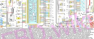
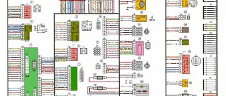
General diagram of the electrical equipment of the VAZ 21074 injector
General diagram of the electrical equipment of the VAZ 21074 injector
1. Electrical connection diagram of the wiring harness of the instrument panel assembly LADA 21074
- — ignition switch unloading relay;
- — relay-interrupter of direction indicators;
- — windshield wiper relay;
- — brake signal switch;
- — switch for headlights and direction indicators;
- — windshield wiper and washer switch;
- — ignition switch;
- - hazard warning switch;
- — instrument cluster;
- — rear window heating switch;
- — rear fog light switch;
- — external lighting switch;
- — heater motor switch;
- — additional resistor for the heater electric motor;
- — heater electric motor;
- — indicator lamp for heated rear window;
- — brake fluid level warning lamp;
- — instrument lighting switch;
- - cigarette lighter;
- - watch;
- - reverse light switch;
- — hand brake sensor;
- — rear fog light relay;
- — block of the instrument panel harness to the ignition system harness;
- — glove box lighting;
- — mounting block.
A1, A2 - grounding points of the instrument panel wiring harness. A3 - grounding points for the heater motor.
2.Electrical connection diagram of ECM LADA 21074 injector
1 - controller; 2 — diagnostic oxygen concentration sensor; 3 — block of the ignition system harness to the right mudguard harness; 4 — block of the fuel level harness to the ignition system harness; 5 and 7 — electrical fuel pump harness pads; 6 — control oxygen concentration sensor; 8 — electric fuel pump; 9 — diagnostic block; 10 — speed sensor; 11 — idle speed regulator; 12 — throttle position sensor; 13 — coolant temperature sensor; 14 — mass air flow sensor; 15 — crankshaft position sensor; 16 — solenoid valve for purge of the adsorber; 17 — ignition coil; 18 — spark plugs; 19 — nozzles; 20 — block of the ignition system harness to the instrument panel harness; 21 — controller power supply fuse; 22 — ignition relay; 23 - ignition relay fuse; 24 — fuse for the electric fuel pump power supply circuit; 25 — electric fuel pump relay; 26 — block of the ignition system harness to the injector harness; 27 — injector harness block to the ignition system harness; A - to the “plus” terminal of the battery; B1 — grounding point of the fuel level sensor harness; B2, ВЗ — grounding point of the ignition system harness; 21074-3724026 — ignition system harness
3. Electrical connection diagram of the wiring harness of the right mudguard assembly LADA 21074.
- — mounting block;
- — block of the right mudguard harness to the left mudguard harness;
- — right side turn signal;
- - right headlight;
- — additional starter relay;
- — windshield washer pump;
- — blocks of the right mudguard harness and connecting starter wires;
- — starter;
- — rechargeable battery;
- — generator.
A1 is the grounding point for the right mudguard wiring harness. A2, A3 - grounding points of the connecting motor wire with the battery and housing.
4. Electrical connection diagram of the left mudguard assembly wiring harness LADA 21074.
- — mounting block;
- — block of the left mudguard harness to the right mudguard harness;
- - left headlight;
- — left side turn signal;
- — oil pressure warning lamp sensor;
- — coolant temperature sensor;
- — brake fluid level sensor;
- — electric motor of the windshield wiper;
- - sound signal;
- — engine electric fan.
A1, A2 - grounding points of the left mudguard wiring harness.
5. Electrical connection diagram of the flat rear wiring harness assembly for LADA 21074.
- — mounting block;
- — flat rear harness block to the ignition system harness;
- — right front door lamp switch;
- — right rear door lamp switch;
- — left front door lamp switch;
- — left rear door lamp switch;
- — right interior lamp;
- — left interior lamp;
- — electric fuel pump with fuel level indicator sensor;
- — rear window heating element;
- — additional brake signal;
- — right lamp;
- — left lamp;
- — left license plate light;
- — right license plate light.
A1 is the grounding point for the rear window heating element. A2 is the grounding point for the license plate light ground harness. A3 - A8 - grounding points of the flat rear wiring harness assembly.
Source
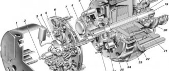
Solenoid relay
The starter, by its design, is a small electric motor, a special coupling (Bendix) of which engages with the flywheel of the power unit for a few seconds, causing the crankshaft to rotate. Despite the small size of the starter, when the engine starts, currents that reach hundreds of amperes pass through it. If power is supplied to this device directly through the ZZ, then no contacts will withstand such loads and will burn out. Therefore, to connect the starter to the power source, a special retractor relay is used, which is designed with contacts designed for high currents. This mechanism is structurally located on the starter housing.
The switching device in question is assigned a number of functions:
- connecting the starter to the power source;
- engagement and retention of the bendix with the engine flywheel;
- turning off the starter power after the engine starts running.
Operating principle
The retractor mechanism operates in the following order:
- When you turn the key in the ZZ, an additional relay is activated.
- Power from the battery is supplied to the traction relay coil.
- Under the influence of a magnetic field, the armature moves inside the winding.
- The starter fork is driven and extends the bendix.
- The starter sprocket engages with the flywheel of the power unit.
- A plate attached to the end of the solenoid relay rod connects the contacts to each other.
With the described actions, the engine starts within a few seconds. After activating the starter, the retractor winding stops working, and the current passes through the holding coil, due to which the armature remains in its extreme position. The presence of two windings reduces battery energy consumption during engine starting.
After the motor starts working, the starter's electrical circuit opens, the current through the holding coil stops flowing, and the armature, due to the spring, returns to its original position. At the same time, the clutch and coin are removed from the relay contacts, the bendix moves away from the flywheel and the starter is disconnected from the battery.
Malfunctions
Since the retractor operates every time the power unit is started and is subjected to high loads, it gradually wears out and fails. Relay malfunctions can be judged by characteristic signs:
- when the engine starts, the starter continues to operate, making a buzzing sound;
- when the engine starts, the relay makes a click, but the starter does not function;
- When you turn the key, the starter spins, but does not engage the flywheel.
Problems can occur for several reasons:
- violation of the integrity of the relay housing;
- problems with the retractor or retention coil;
- burning of contacts;
- weakening of the spring.
All of the listed problems occur as a result of natural wear, burnout of the windings, or destruction of parts of the assembly.
Examination
You can check the relay in two ways - without dismantling the starter and with the device removed. Let's consider both options.
By car
We carry out diagnostics with a multimeter or “control”:
- Visually assess the integrity of the relay wiring.
- We check the operation of the relay, for which we turn the key in the ignition switch and listen to the starter: if the click is not heard, the relay is considered faulty.
- If there is a characteristic sound, but the starter does not turn, the contact coins in the relay itself may be burnt. To check, remove the chip that comes from the ZZ and close the two threaded contacts together. With this connection, the starter will be powered bypassing the relay. Rotation of the starter will indicate a problem with the switching element.
- We connect the multimeter to the “+” relay, i.e. to the contact where power comes from the battery, and connect the minus to ground. We turn on the ignition and if the voltage is below 12 V, then most likely the battery charge is not enough to start the engine, but enough to trigger the relay.
Video: diagnosing the starter without removing it from the car
With the starter removed
Before dismantling the starter, you need to perform several steps that will allow you to determine the problem:
- we check the condition of the battery and starter terminals, the battery charge and, if necessary, clean the contacts with sandpaper;
- Determine the functionality of the starter relay.
If the above actions did not produce results and the starter still does not work properly, remove it from the car. We clean the assembly from dirt, clean the contacts, and then check:
- We install the starter near the battery.
- We connect the battery and the starter using thick wires with “crocodiles”, for example, a “lighting” kit. We connect the minus of the battery to the housing, and connect the plus to the contact of the traction relay. If there is a distinct click of the relay and the bendix moves out, this indicates the working condition of the relay. If the retractor does not work, it means it needs to be replaced or repaired.
Video: checking the starter traction relay
Which relay to choose
Solenoid relays are either collapsible or non-dismountable. The first design is older, but such products are interchangeable with the second option. For the VAZ 2107 and other “classics”, the device in question is produced by several manufacturers:
- "KATEK" and "KZATE" (Samara);
- BATE (Belarus);
- "Kedr" (Chelyabinsk);
- Dynamo AD (Bulgaria);
- Iskra (Belarus).
From the above list, the products of “KATEK” and “KZATE” are the highest quality. The cost of solenoid relays from these manufacturers is about 700–800 rubles.
Traction relay repair
Dismantling the solenoid relay is necessary in two cases - to repair or replace the mechanism. Removing it is not difficult, but first you will need to remove the starter itself from the car.
Removing the starter and relay
You will need the following list of tools for work:
- flat screwdriver;
- key for 8, 10 and 13.
The procedure is carried out as follows:
- Remove the negative terminal from the battery.
- Unscrew the starter mount to the clutch housing.
Disassembly
The solenoid relay is disassembled in order to replace or clean the contacts (nickels):
- Using a wrench or socket 8, unscrew the fastening of the relay cover to the body.
Wiring diagram VAZ 2107 injection wiring
In the mid-90s, a massive transition of Russian models from a carburetor to an injection power system began. This requalification also affected the VAZ 2107 and 21074 cars. As a result, the model received new elements that structurally distinguish it from its predecessor:
- electric fuel pump. It takes fuel from the tank, maintaining constant pressure in the fuel line. The carburetor version had a mechanical fuel pump;
- fuel injectors that inject directly into the combustion chamber. Therefore, the fuel-air mixture is formed directly in the combustion chamber. On the previous modification, the mixture was formed due to the opening of the carburetor air damper;
- new engine control unit, which determines the moment of injection and forcibly performs it. The fuel mixture is forced into the cylinders by the injection system, while in the carburetor the fuel is supplied due to rarefied pressure after the valve opens.
New power system
To understand why so many different electrical equipment are installed on the car, and what the electrical wiring unites, you need to understand the principle of operation of the new power system.
Advice: For general development, it’s a good idea to watch a video on the Internet that clearly explains the difference in the operation of these systems.
The main difference between an injection system and a carburetor system is as follows:
- The electric fuel pump constantly increases the pressure in the fuel line (in the carburetor version there is no pressure, and the pump itself is mechanical);
- The air-fuel mixture is formed directly in the cylinder (injection system), whereas on the “classic” it is formed in the carburetor;
- Electric injectors are responsible for injecting fuel into the cylinders (nozzles in the carburetor, and from there the air-fuel mixture enters the intake manifold and then into the cylinders);
- The timing of injection is determined by the ECM (in the carburetor, fuel is sucked in when the intake valve opens).
Differences in electrical wiring
The platform for creating the VAZ 21074 car was the VAZ 2107 model. And although the same 1.6-liter engine was installed on the “seventy-four,” the carburetor was replaced with an injector.
This entailed changes, as a result of which the electrical wiring of the VAZ 21074 to the injector differs from the standard carburetor version:
- Added wiring harness from controller to fuel frame;
- Added wires to the radiator area - for sensors and fan;
- Wiring for the electric fuel pump has appeared.
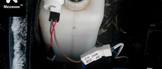
For reference: the fuel pump on the carburetor VAZ 2107 was of a mechanical type and was installed directly on the power unit. For safety reasons, the electric fuel pump was installed away from the engine compartment - in the rear of the car.
The material on our website VAZ 21093 wiring diagram: service features will give you more information on this issue.
New sensors
Since the injection system operates according to pre-compiled algorithms (firmware), to activate them, the electronic system requires readings of numerous vehicle operating parameters.
For this purpose, additional sensors were installed:
- mass air flow;
- oxygen concentration;
- throttle position;
- vehicle speed;
- crankshaft position;
- gravity valve in the fuel line;
For reference: all sensors have connectors for connection. And the additional wiring has terminals for connection with the required pinout.
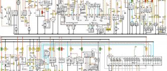
Explanation of symbols
The wiring diagram contains the following symbols:
- 1 – radiator fan drive motor;
- 2 – mounting block block;
- 3 — idle speed sensor;
- 4 – engine ECU;
- 5 – potentiometer;
- 6 – set of spark plugs;
- 7 – ignition control unit;
- 8 – electronic crankshaft position sensor;
- 9 – electric fuel pump;
- 10 – indicator of the number of revolutions;
- 11 – lamp for monitoring the health of electronic systems and the brake system;
- 12 – ignition system control relay;
- 13 – speedometer sensor;
- 14 – special factory connector for reading errors using the BC;
- 15 – injector harness;
- 16 – adsorber solenoid valve;
- 17, 18, 19,20 – fuse box for repairing the mounting block that protects the injection system circuits;
- 21 – electronic fuel pump control relay;
- 22 – electronic relay for controlling the exhaust manifold heating system;
- 23 – exhaust manifold heating system;
- 24 – fuse protecting the heater circuit;
- 25 – electronic air sensor;
- 26 – coolant temperature control sensor;
- 27 – electronic air damper sensor;
- 28 – air temperature sensor;
- 29 – pressure control sensor and low oil pressure lamp.
Download the electrical diagram of the VAZ 2107 injector
The general circuit of electrical equipment consists of individual aggregate units:
- special factory connector for connecting the on-board computer. Allows you to decipher engine errors;
- tachometer indicating the number of revolutions;
- Check Engine Light;
- starter;
- air damper sensor;
- cooling fan drive for radiator;
- drive control relay;
- Engine ECU;
- crankshaft position sensor;
- electric fuel pump with control relay;
- fuel filter;
- battery and charging relay;
- egnition lock;
- idle speed sensor.
Detailed wiring in a large format with a nozzle can be downloaded from the link. A small image (300 kb), with a resolution of 1604 pixels in height and 1022 pixels in width, will allow you to carefully examine all the necessary components and parts, and will also greatly help with electrical repairs on a VAZ.
Injector maintenance
Since the injection power system is quite complex, during the operation of the car there is a need to eliminate failures and failures. You can service the car yourself if you have a detailed diagram. In particular, engine management systems:
To troubleshoot you need:
- availability of electronic testers (their price is low - you should definitely buy them);
- adapters through which the tester is connected to the diagnostic connector.
By comparing the measurement results with operating parameters, you can easily identify an electrical circuit operating with deviations. And only then, when analyzing it, detect a non-working device: sensor or wiring.
Additional designations
The fuses of the VAZ 2107 car are located as follows:
- taillights and reversing lights;
- electric motor of the heater fan, headlight washer and glass wiper pumps;
- indicator for turning on the rear window heater VAZ 2107;
- direction indicators and hazard warning relays;
- fog lights;
- tachometer, voltmeter;
- control lamps for oil pressure, fluid, fuel level and reserve indicators on the instrument panel, instrument panel lighting;
- cigarette lighter and clock;
- VAZ sound signal;
- interior lighting (up to 2000 there was one lamp on the ceiling, for those manufactured after 2000 there were two lamps on the rear door pillars);
- high beam headlights;
- high beam warning lamp;
- engine compartment lighting and license plate lighting;
- glove compartment lighting;
- right headlight;
- left headlight.
A detailed wiring diagram of the VAZ 2107 will help you understand the intricacy of electrical wiring elements, find the air cover switch or the windshield and headlight wiper relay.
Source
VAZ-2107 diagram
The VAZ-2107 car was produced from 1982 to 2014. Here are colored wiring diagrams (for the injector and carburetor) with a description of all the elements for various modifications. The information is intended for self-repair of cars. Electrical circuits are divided into several blocks for ease of viewing via a computer or phone; there are also circuits in the form of a single picture with a description of each element - for printing on a printer.
The “sevens”, like most modern cars, use a single-wire circuit for supplying electricity to electrical equipment. The other terminal of the consumer is always connected to the ground of the machine to which the negative terminal of the battery is connected. This solution allows not only to simplify the design of the on-board network, but also to slow down corrosion.
Application of generators.
The VAZ 2107 charging scheme depends on the type of generator used in the car. To recharge the battery on VAZ-2107 (2104, 2105) cars with a carburetor engine, a G-222 type generator or similar with a maximum output current of 55A is used. On VAZ-2107 cars with an injection engine, a generator of type 5142.3771 or similar, the so-called high-energy generators, with a maximum output current of 80 - 90A is used, depending on the design. It is possible to install more powerful generators with an output current of up to 100A. All types of alternating current generators with a built-in rectifier unit (diode bridge) and a voltage regulator, made in one housing with brushes or a removable one mounted on the housing.
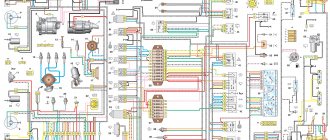
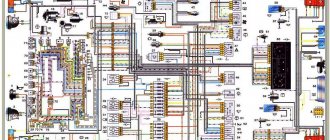
Electrical diagram VAZ-2107 carburetor
Electrical diagram of VAZ 2107, 21074 produced in 1988-2001 with generator 37.3701
- block headlights
- side direction indicators
- accumulator battery
- starter relay
- carburetor electro-pneumatic valve
- carburetor microswitch
- generator 37.3701
- gearmotors for headlight cleaners *
- Fan motor switch sensor
- engine cooling fan motor
- sound signals
- distributor
- spark plug
- starter
- coolant temperature gauge sensor
- engine compartment lamp
- low oil pressure warning sensor
- low brake fluid level indicator sensor
- windshield wiper motor
- carburetor electro-pneumatic valve control unit
- ignition coil
- headlight washer pump motor *
- windshield washer pump motor
- mounting block
- windshield wiper relay
- hazard warning and direction indicator relay
- brake light switch
- reverse light switch
- ignition relay
- ignition switch
- three lever switch
- hazard switch
- socket for portable lamp**
- heater fan switch
- additional resistor for the electric motor of the heater (stove)
- rear window heating indicator lamp
- low brake fluid level warning lamp
- signaling unit
- heater fan electric motor
- glove compartment lamp
- light switches on the front door pillars
- switches for warning lights of open front doors ***
- front door open warning lights ***
- connection block
- cigarette lighter
- watch
- instrument light switch
- diode for checking the serviceability of the low brake fluid level indicator lamp
- fuel level indicator
- fuel reserve indicator lamp
- speedometer
- turn signal indicator lamp
- carburetor choke indicator lamp
- battery charge indicator lamp
- carburetor choke warning switch
- instrument cluster
- econometrician
- light switches on the rear door pillars
- coolant temperature gauge
- tachometer
- parking brake indicator lamp ("handbrake")
- low oil pressure warning lamp
- high beam indicator lamp
- indicator lamp for turning on external lighting
- voltmeter
- parking brake indicator switch ("handbrake")
- outdoor light switch
- rear window heating switch with backlight
- rear fog light switch with on/off indicator *
- fog light circuit fuse
- lampshade ****
- tail lights
- level indicator and fuel reserve sensor
- connectors for connecting to the rear window heating element *
- license plate lights 2107
Wiring diagram VAZ-2107 carburetor - full view:
Failure of the main vehicle systems
The reason for the sudden failure of many components of the VAZ 2107 car may be damage and failure of electrical wiring elements.
The most common wiring failures are listed below:
- A common defect is a blown fuse link caused by a circuit overload or short circuit. Since the electrical circuit of the VAZ 2107 often uses old-style fuses, oxidation or loosening of the contact clamps in the mounting block often occurs. To correct these faults, replace the fuse or clean the contacts. The latest car releases used mounting blocks with blade fuses, which provide better contact and more reliable operation of the electrical circuit.
- A more complex case is the burning or oxidation of conductive tracks in the mounting block. To repair, the unit is removed from the car, the damaged areas are soldered and covered with protective varnish. In case of critical damage, the unit must be replaced.
- When a section of the wiring is short-circuited, the fuse-link will constantly burn out. To find a damaged element, you need to test the circuit with a multimeter. Replaced wires should be carefully laid along the standard route. An open circuit is also determined by the continuity of the wires.
- If there is a problem with the components of the injection system, the Check Engine indicator light on the instrument cluster may turn on. The cause may be sensor failure or broken circuits. To find the causes of damage, you should diagnose the injection system using a test device connected to the diagnostic connector. The error codes available in the system can be deciphered and repairs are made based on this data.
- The cause of complete inoperability of the electrical system may be a discharged battery or oxidation of the negative wire that is connected to the body. A low battery is indicated by a dim glow of the control lamps and their complete shutdown when a load is connected (horn or an attempt to crank the engine with the starter).
- A burning battery charging lamp with the engine running indicates a malfunction of the generator or an open circuit connecting the generator to the battery.
- Light pulsations when the engine is running are a symptom of a burnt-out control relay on the generator. The relay must be replaced, since operating the vehicle with increased voltage in the on-board network is unacceptable.
Mounting block connection diagram
P1 — relay for turning on the heated rear window; P2 - relay for turning on the headlight cleaners and washer; P3 - relay for turning on sound signals; P4 - relay for switching on the electric motor of the engine cooling system fan; P5 - headlight high beam relay; P6 - low beam headlight relay; A - the order of conditional numbering of plugs in the mounting block blocks. The outer number with the letter “Ш” in the plug designation is the block number, and the inner number is the conventional number of the plug.
Schemes of individual blocks of the seven
Power supply system
Power plant starting system
1 - starter; 2 - relay; 3 — ignition switch; 4 - battery
Ignition system
1 - generator; 2 — ignition switch; 3 - distributor; 4 - breaker; 5 — candles; 6 - coil; 7 - battery
Contactless ignition system
External and internal lighting
Windshield wipers and washers
1 — electric motors of the windshield wiper; 2 — washer motor; 3 — mounting block; 4 — ignition switch; 5 - washer switch
Cooling Fan
1 — fan electric motor; 2 - sensor; 3 — mounting block; 4 - ignition relay; 5 - ignition switch.
Wires for connecting electrical appliances
| Connection type | Section, mm 2 | Insulation color |
| Negative terminal of the battery - vehicle ground (body, engine) | 16 | Black |
| Starter positive terminal - battery | 16 | Red |
| Positive contact of the generator - plus battery | 6 | Black |
| Generator - black connector | 6 | Black |
| Terminal on the generator “30” – white MB block | 4 | Pink |
| Starter connector “50” – starter relay | 4 | Red |
| Starter Start Relay - Black Connector | 4 | Brown |
| Ignition switch relay - black connector | 4 | Blue |
| Ignition switch output “50” – blue connector | 4 | Red |
| Ignition switch connector “30” – green connector | 4 | Pink |
| Right headlight plug - ground | 2,5 | Black |
| Left headlight plug - blue connector | 2,5 | Green, gray |
| Generator output “15” – yellow connector | 2,5 | Orange |
| Right headlight connector - ground | 2,5 | Black |
| Left headlight connector - white connector | 2,5 | Green |
| Radiator fan - ground | 2,5 | Black |
| Radiator Fan - Red Connector | 2,5 | Blue |
| Ignition switch output “30/1” – ignition switch relay | 2,5 | Brown |
| Ignition switch contact “15” – single-pin connector | 2,5 | Blue |
| Right headlight - black connector | 2,5 | Grey |
| Ignition switch connector “INT” – black connector | 2,5 | Black |
| Six-pin block of the steering column switch - “ground” | 2,5 | Black |
| Two-pin block of the steering column switch - glove box illumination lamp | 1,5 | Black |
| Glove compartment light - cigarette lighter | 1,5 | Black |
| Cigarette lighter - blue block connector | 1,5 | Blue, red |
| Rear window defroster - white connector | 1,5 | Grey |
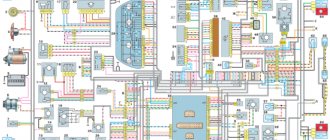
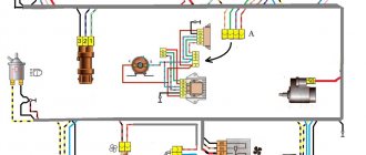
Car wiring diagram
1 – radiator fan drive motor; 2 – relay and fuse block (mounting block); idle speed sensor; 4 – engine control unit; 5 – potentiometer; 6 – set of spark plugs; 7 – ignition control unit; 8 – electronic crankshaft sensor; 9 – electric fuel pump; 10 – tachometer 2107; 11 – lamp for monitoring the health of electronic systems; 12 – ignition system control relay; 13 – speed sensor; 14 – diagnostic connector; 15 – set of injectors; 16 – adsorber solenoid valve; 17, 18, 19 – fuse block protecting the injection system circuits; 21 – electronic fuel pump control relay; 22 – electronic relay for controlling the intake pipe heating system; 23 – intake pipe heating system; 24 – fuse protecting the heater circuit; 25 – electronic oxygen level sensor; 26 – cooling system temperature control sensor; 27 – electronic air damper sensor; 28 – air temperature sensor; 29 – pressure control sensor.
Fuse and relay diagram 2107
On newer “sevens” a block with 17 fuses and 6 relays is installed. VAZ 2107 fuses on the “new” unit protect the following electrical circuits and devices:
- Reversing lamps, heater fan, rear window defroster warning lamp and relay, rear wiper motor and rear washer pump.
- Electric motor for front wipers.
- Reserve socket.
- Reserve socket.
- Power supply for heated rear window.
- Clock, cigarette lighter, power socket “carrying”.
- Signal and radiator fan.
- Turn signal lamps in emergency mode.
- “Fog lights” and a relay that regulates the voltage of the on-board network.
- Instrument panel lamps.
- Brake light bulbs.
- Right high beam headlight.
- Left high beam headlight, high beam warning lamp.
- Side lights (rear right, front left), license plate and engine compartment lighting.
- Side lights (rear left, front right), glove compartment and cigarette lighter lamps.
- Low beam (right lamp).
- Low beam (left lamp).
The block relays perform the following functions:
- Heated rear window relay.
- Headlight cleaner and washer relay.
- Signal relay.
- Cooling system electric fan relay.
- High beam relay.
- Low beam relay.
The fuse block of the VAZ 2107 (injector) is no different from the block on the carburetor “seven”. Injection models are simply equipped with an additional relay and fuse box installed in the cabin under the glove compartment. The block includes three relays - the “main” relay, the fuel pump relay and the fan relay.
Differences in generator connection diagrams.
The VAZ 2107 charging scheme differs depending on the year of manufacture of the car, but not significantly. The difference lies in the presence or absence of a charge indicator lamp on the instrument panel, the method of connecting it, and the presence or absence of a voltmeter. But this only applies to carburetor cars. On cars with an injection engine, the circuit does not change and is exactly the same as on the first cars.
Charging diagram before 1986.
Let's consider the VAZ 2107 charging circuit with a control lamp that operates through a relay. It was used on cars produced until 1986. This circuit is characterized by the presence of a battery charge indicator lamp.
When the ignition is turned on, the plus from the lock through fuse No. 10 “Instrument panel, direction indicators” is supplied to the relay of the battery charge indicator lamp to the contact and output of the coil. The second terminal of the coil is connected to the central terminal of the stater, where all three windings are connected. The relay contacts are constantly closed, the control lamp lights up. When the engine is running, when the generator begins to produce current, an alternating voltage of about 7V appears on the windings. Current begins to flow through the relay coil and the armature is attracted, opening the contacts.
At the same time, current flows to the output of generator No. 15 through fuse No. 9. The excitation winding receives power through the brush voltage regulator.
Connection diagram after 1996 (carburetor engine).
The VAZ 2107 charging circuit differs from the previous one only in the absence of a warning lamp relay. Excitation in this case occurs in the same way as in the previous case. The presence and level of charge is determined by a voltmeter on the instrument panel.
Charging circuit for injection engines.
This scheme is the same as on other VAZ models. The difference from the previous ones is in the method of exciting and monitoring the health of the generator. Monitoring is carried out using a warning lamp and a voltmeter on the instrument panel. Through the charging lamp, the initial excitation of the generator is also carried out at the moment of operation. During operation, the generator operates autonomously, that is, excitation comes directly from output 30 of the generator.
When the ignition is turned on, power through fuse No. 10 is supplied to the charging lamp in the instrument panel. Then through the mounting block to output 61 of the generator. The voltage regulator receives power through three additional diodes, and through it the excitation winding of the generator. At the same time, the control lamp will light up. When the generator starts working, a voltage higher than the battery voltage will appear on the plates of the rectifier bridge. In this case, the control lamp will go out, since the voltage on the side of the lamp on the additional diodes will be lower than on the side of the stator winding and the diodes will close. If the control lamp lights up when the generator is running, then one or more additional diodes are broken.