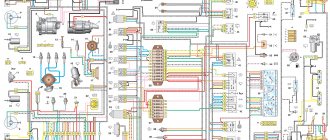
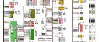
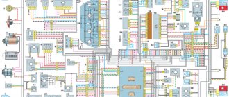
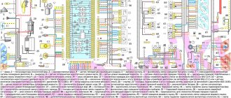
Electrical diagram of Daewoo Nexia
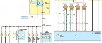
The Daewoo Nexia electrical circuit diagram of which is presented in this section was not developed yesterday, and this greatly facilitates the repair of the main components of the car. The design of the car as a whole repeats the Opel Cadet of the 80s. Minor changes have been made to decorative elements and optics, and there are also options with a twin-shaft 16-valve engine, which in no way affected the electrical diagram that we posted below.
As you can see, the scheme is simple and to some extent identical to VAZ cars, and those who are familiar with the old Cadet will understand it without any difficulty.
Eliminating the cause of burnout
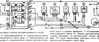
It should be noted that replacing the contact group with a working one helps for a while. For high-quality repairs, it is necessary to eliminate the cause of burnout: reduce the current load on the contacts. You can strengthen the weak point of the Daewoo Nexia by installing additional relays according to the diagram:
When using two relays, the load on a group of contacts is halved
This method will help extend the service life of the contact group by more than 2 times. Anyone can improve the electrical ignition circuit of a Korean car.
Fines for crossing the stop line and speeding will no longer bother you!
Nexia fuse box
As in all European cars of those times, the Nexia has a fuse block with fork-type fuses. This is much more convenient than the old cartridge elements. Each fuse is responsible for a specific section of the circuit. In the event of an overload or short circuit, the fuse does not allow harm to electrical equipment located in the circuit after it. The basic rule, which cannot be neglected, is that any use of jumpers that short-circuit the contacts tightly, or bugs, is unacceptable. It is also unacceptable to use fuses that do not correspond to the rating. If the fuse has a resistance lower than the rated value, it will blow, and if it is significantly higher, it will burn out the equipment that it was supposed to protect.
For ease of use, fuses have housings of different colors. 10 amp fuses have a red body, 20 amp yellow, 30 amp fuses have a green body. The fuse board is located in the same housing as the relay block, and the entire mounting block is located on the driver's side under the instrument panel.
Explanations for symbols on electrical circuits of daewoo matiz | automotive wiring diagrams
At first glance, the electrical circuit diagrams discussed in the Matiz car section cause complete confusion. After the general diagrams of domestic cars that are familiar to us, the diagrams of foreign cars are a dark forest. However, this is not quite true. Taking the circuit apart into parts has its advantages.
And if you carefully study this section on reading electrical circuits, then everything becomes clear and simple. Take, for example, power circuits. If you do not know whether power is or should not be supplied at the moment to the section of the circuit under study, voltage.
Just look at the designation of the power cord and compare it with the table below. Let's say you're looking at a light switch circuit, you look at the diagram and it's connected to wire number 30.
This means that power, its positive source, regardless of the position of the key in the ignition switch, is constantly present on this conductor. The same goes for the fuse for this circuit.
By marking it on the diagram, we find out the maximum current load that it can withstand - in this case 80 Amperes, where it is located - in this case in the fuse box in the engine compartment and through which contact - in this case 1, which connector - here as an example connector C203.
In addition, we immediately determine the color of the harness in which the desired wire is located. For specialists, it is not particularly difficult to remember the letter indices of the designations. Moreover, there are not so many of them. And in practice, understanding the diagrams every day, they quickly get used to and understand the usefulness of these notations. If you yourself want to find and fix a breakdown in any Daewoo Matiz electrical equipment circuit, this page will help you.
Problems with power windows
The build quality of the Daewoo Nexia, unfortunately, very much depends on the factory at which the car was assembled. Most often, problems with window regulators arise on Russian-assembled Daewoos, and the components supplied to both Uzbekistan and Poland are, apparently, exactly the same. However, if problems arise with the window regulators, you need to make sure that the problem is in the electrical part. If everything is fine with the mechanics, then you should check the fuse in the mounting block.
If everything is in order with it, then most likely it is in the lift control unit. The main unit is located in the driver's door armrest. The most likely failure is failure of the control keys or lack of contact in the control unit. The fact is that the door is constantly subject to vibration, so due to poor quality assembly, the contacts may simply come off.
Fuses and relays Daewoo Nexia N150
Most electrical circuits are protected by fuses. Powerful consumers (headlights, cooling system fan motor, electric fuel pump, etc.) are connected via a relay. The information is relevant for Daewoo Nexia 2008, 2009, 2010, 2011, 2012, 2013, 2014, 2015, 2016 models.
Fuses and relays are located in the mounting block.
To access the mounting block, remove the protective cover in the instrument panel.
On the inside of the mounting block cover there is a diagram of the location of fuses and relays installed on the outside of the block. The rating of the fuses, the circuits they protect and the purpose of the relay are given in the tables.
Location of fuses and relays on the outside of the mounting block
Location of fuses and relays on the inside of the mounting block
| Purpose of the relay in the mounting block | |
| Relay number | Relay purpose |
| K1 | Cooling Fan (High Speed) |
| K2 | Direction indicators. |
| K3 | Fuel pump. |
| K4 | Fog lights. Rear fog lights. |
| K5 | Side lights, fog lights. |
| K6 | Headlights. |
| K7 | Cooling fan (low speed). |
| K8 | Air conditioning compressor clutch. |
| K9 | Sound signal. |
| K10 | Headlights. |
| K11 | Melodious signal. |
| K12 | Turning on the 4th speed heater fan. |
| K13 | Ignition system. |
| K14 | Windshield cleaner. |
| K15 | Rear window heating timer. |
| Circuits protected by fuses | ||
| Fuse designation (see photo) | Rated current, A | Protected Circuits |
| F1 | 10 | ECU (battery circuit). |
| F2 | 10 | Side lamps, license plate lights, instrument cluster and control lights. |
| F3 | 15 | Ignition system relay circuit. |
| F4 | 20 | High beam headlight lamps. |
| F5 | 10 | Low beam lamp of the left headlight. Electric drive for adjusting the direction of the light beam of the left headlight. |
| F6 | 10 | Low beam lamp for the right headlight. Electric drive for adjusting the direction of the light beam of the right headlight. |
| F7 | 30 | Electric fuel pump, fuel injectors. |
| F8 | 20 | Turn indicators, brake lights. |
| F9 | 30 | Windshield cleaner. |
| F10 | 10 | Fuel tank filler flap drive. |
| F11 | 10 | Relay for turning on the electromagnetic clutch of the air conditioning compressor. |
| F12 | 30 | Cooling fan motor (low speed). Heater fan. |
| F13 | 20 | Reversing lamps. Generator excitation circuit. Instrument cluster, cigarette lighter, melodic sound signal, clock. |
| F14 | 30 | Sound signal. Cooling fan (high speed). |
| F15 | 20 | Alarm. Interior lamp. Trunk light bulb. |
| F16 | 30 | Window lift motor gearboxes. |
| F17 | 10 | Audio system (circuit from ignition switch). |
| F18 | 30 | Trunk lid lock control. Rear window heating timer. Central locking. Audio system (battery circuit). |
| F19 | 30 | Heater fan 4th speed relay. |
| F20 | 30 | Fog lights. |
Air conditioning Daewoo Nexia
Some Nexia cars were equipped with air conditioning. It was included in the most expensive configurations and worked quite reliably with proper maintenance and operation. The main reasons for the failure of the air conditioner, which relate to electrical equipment, were failures of the electromechanical clutch of the compressor drive and breakdowns of the climate control system. Despite the fairly reliable design of the air conditioner itself, there were annoying errors when assembling components, which sometimes led to premature wear of the compressor and evaporator.
Since the operation of the air conditioner is connected to the heating and blowing system, it could not help but respond to frequent failures of the air circulation drive motor. The engine itself cannot be repaired, but before you say goodbye to it, it’s worth checking the circuit right down to the fuses. If there is voltage on the circuit after the fuse, it is quite possible that the contacts in the motor power supply are to blame.
How to check and make repairs
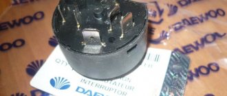
Any car enthusiast can check the serviceability of the group of contacts in the ignition switch. Performance is determined by the appearance of the plastic case and the presence of carbon deposits on the contacts inside the group. To get to the part, it is enough to arm yourself with a Phillips and straight screwdriver.
- We remove the plastic under the steering wheel, it is secured with screws.
First you need to remove the protective plastic under the steering wheel.
The connector can be easily removed from the group of contacts with a simple screwdriver
Using a thin flat screwdriver, unscrew the screw that secures the group in the ignition switch housing
If the case is not damaged, be sure to inspect the internal contacts. To do this, carefully disassemble the case. If carbon deposits are found, remove it with a sharp knife or screwdriver. This temporary procedure will help along the way. As soon as possible, contact an electrician at a service station or replace the contact group yourself.
Ignition system
The contactless ignition system of the Daewoo Nexia works stably and there are no outright complaints about it. In the event that all elements are serviced and checked for mechanical integrity in a timely manner. First of all, this applies to highly loaded devices:
- ignition distributor;
- coils;
- high voltage circuit;
- electronic control unit.
Since 2008, an ECU without feedback has been installed on the car, so its operation has become more stable. In addition to all other corrective functions, the ECU also controls the operation of the ignition system. The control unit adjusts the operation of the system based on the following data:
- crankshaft rotation speed;
- throttle opening angle;
- data from the catalytic converter oxygen sensor;
- temperature and pressure of incoming air.
The ignition system must quickly respond to ECU signals and make adjustments to the advance angle. In case of any abnormal readings, the system informs the driver about the need for maintenance or repair.
Thus, any faults in the electrical equipment of the Daewoo Nexia can be localized, and the diagram posted on the page will help with this. Control the on-board voltage, and have a good trip!
The main symptoms of a malfunction of the ignition switch contact group
The main signs by which you can understand that the contact group is burnt out and does not work or will soon break. You can touch it, the contact group gets very hot, turning on the low beam, heater, windshield wipers, radio - at this moment there is a colossal load on the contact group, the contacts get very hot and the plastic begins to melt. The contact group will work for some time, but due to the fact that the plastic has melted, the contact has become even worse - a breakdown is not far off.
So the first sign is strong heating of the contact group. The second and main sign is the smell of burnt wires or plastic. If you remove the steering column casing, you will smell a burning smell and see a picture - blackened, burnt wires and a corrected contact group. Consider this article your salvation, you just need to read it to the end.
There is also a situation when you turn the key, but the car does not react. Nexia has a standard problem. This means 99 percent that your contact group has received a hitch. But don’t despair, if you don’t have a contact group at hand, you can drive normally by starting the engine with wires (see How to start a Nexia engine with wires without keys). If when you turn the key, the car does not start, then the contact group is to blame. It also happens that the starter simply does not turn when you turn the key - this is the same trouble.
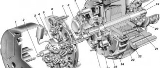
Features of electrical equipment
The general electrical circuit of a Daewoo Matiz or Nexia car includes the following subsystems:
- The ignition system includes a lock, a starter unit, a generator unit and a battery.
- Temperature controller, pressure and speed sensors, XX valve, dampers.
- Diagnostic unit, as well as torque converter blocking, fuel pump electric motor.
- Anti-theft system, immobilizer, central locking.
- Transmission control unit.
- Security system, including airbags, sensors.
- Lighting devices - fog lights, brake lights, headlights, headlights, interior lights, etc.
- Sound signal.
- Trunk lock, warning buzzer mechanism.
- Rear window defogger.
- Electric windows.
- Ventilation system, including stove, air conditioner.
- The dashboard, where the main parameters of the car are displayed.
- Anti-lock braking system.
- Headlight adjustment mechanism.
- A mounting block with fuses, where all safety devices designed to protect circuits are concentrated.
Why does the ignition switch contact group get hot?
First you need to remove the contact group. You can see the numbers on the contact group (see photo):
As you can see, there are only 5 contacts per kg of the ignition switch:
R - rare on rare 6-pin kg
By turning the key we close the following contacts:
Initial key position “I”: closed “30”+”R”
Initial position of the key “I” + the key is recessed into the ignition switch: “30”+”R”+”Ka” closes
Position “II”: “30”+”Ka” are closed
Position “III” is closed “30”+”Ka”+”15a”+”15″
Starter position: closed “30”+”50″+”15″+”Ka
Why is the contact group burning out so quickly? I hope no more questions arise. All consumers of the car pass through this thing (see photo below), this is the whole problem, to solve it you need to unload the currents using a relay.
The main sources of consumption arise when contacts 30 and 15 are closed, so they need to be unloaded from this current. Installing an unloading relay would be the right option, so you can forget about the problem of burnout of the contact group on the Nexia.