One of the most common wiring problems is current leakage. This way you can create operating conditions for the motor, under which the battery voltage is measured. Anti-theft system, immobilizer, central locking. Take, for example, power circuits.
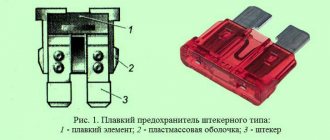
An example of reading electrical diagrams of Daewoo Matiz. Generator Matiz To prevent wiring breakage when laying new wires, they must be additionally insulated. Connection diagram for fog lights and fog lamps in the rear light 1.0:
Now you only need to find out which consumers are connected to this section of the electrical circuit, after which the wiring itself is diagnosed. The author of the video is Alexander Shestopalov. Contacts are oxidized or burned. If there are cracks in the case, it is possible that electrolyte is leaking out of them, which contributes to the destruction of the battery. If you do not know whether power is or should not be supplied at the moment to the section of the circuit under study, voltage. To date, the third generation of Daewoo Matiz M has already been released. Contact group of the ignition switch: device and replacement
A little history of Daewoo Matiz
This car model has been produced since 1998. To date, 2014, the third generation of Daewoo Matiz (M300) has already been released. Matiz of the first generation (M100? M150) and second (M200? M250) Hatchback has 5 seats. All models are equipped with a manual gearbox, and the consumer has a choice of engines: 0.8 liters or 1. After a slight restyling of the car in 2012 (the M200 model was released), in China it was called Chevrolet Lechi. Also there, the car once again underwent minor modifications and became known as “Baojun Lechi” with engines of 1.0 liters (69 hp) and 1.2 liters (86 hp).
Video about the crash test of Daewoo Matiz 1,2 and 3rd generation, respectively - 2000, 2005 and 2009:
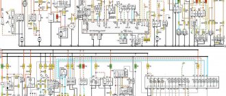
Electrical diagrams of Daewoo Matiz:
1. Numbering of contacts in electrical connectors:
2. Diagram for starting the Daewoo Matiz 1.0 l engine and charging the battery:
3. Electrical diagram for starting the engine and generator connections (0.8 l engine):
4. Engine management system 1.0L:
8. Electrical circuits of the Daewoo Matiz 0.8 l engine management system:
11. Electrical diagram of Daewoo Matiz: reversing lamps, brake lights, side lights and license plate lights:
12. Connections of the relay and fuse box located under the hood of the car (1.0 l engine):
16. Connections of the relay and fuse box located in the car interior (1.0 l engine):
18. Connection diagram of relays and fuses (0.8 l engine):
19. Wiring diagram of the Daewoo Matiz 1.0 liter instrument cluster:
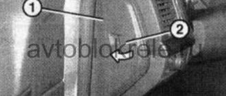
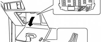
Cabin mounting block
In the Matiz interior, the mounting block is located under the dashboard, on the left side (above the driver’s left knee). The most convenient way to operate it is to sit in the passenger seat, lie down on the driver’s seat and tilt your head back or sideways towards the pedals so that you are facing the mounting block, then the mounting block and the fuses in it will be visible.
Or you can open the driver's door, place something on the threshold, sit next to the car and look under the dashboard. It’s not very convenient, considering that the car is mainly for women, but what can you do, it’s what it is.
Interior fuses
F1 (10 A) - dashboard, sensors and warning lights, immobilizer, clock, alarm . If the sensors on the dashboard have stopped showing and the backlight has disappeared, check the panel connector on the back side, it may have popped out or the contacts have oxidized. Also check the wires and connectors on the back of the mounting block for this fuse.
When you turn on the ignition, the immobilizer icon on the panel lights up - this means that it is looking for a chip key. If you successfully find the key, the lamp goes out and you can start the car. To add a new key to the system, you need to flash/train the ECU to work with the new key. If you do not understand electrical equipment, it is better to contact a car service. If the car is not running, you can find and call a mobile electrician.
F2 (10 A) - airbag (if equipped).
F3 (25 A) - electric windows . If the power window of one door stops working, check the integrity of the wires at the bend point when opening the door (between the body and the door), the control button and its contacts. It could also be a problem with the window lift mechanism. To get to it, remove the door trim. Check the serviceability of the motor by applying a voltage of 12 V to it, the absence of distortion of the glass in the guides, the integrity of the gear and cable (if the window lifter is a cable type).
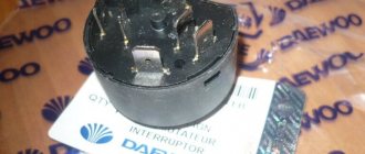
F4 (10 A) - direction indicators, turn signal lamps on the dashboard . If your turn signals stop working, check repeater relay B; it may click when you turn on the turns, but not work. Replace with a new relay, also check the contacts in the fuse sockets and its serviceability. The relay in some models may not be located in the mounting block, but under the dashboard on the driver's side. If the problem is not in the relay/fuse, then most likely in the steering column switch, check its contacts and wires.
Daewoo Matiz Sports › Logbook › Pinout of ECU Fenix 5MR / Siemens k115444004b
Hi all! There are plans ahead to install a tachometer, so I was puzzled by searching for ECU diagrams in order to understand what to connect where. I offer you materials I found on the Internet; they are not so easy to find now. I have a certain Siemens k115444004b, aka 96389098, aka Fenix 5MR.
Source: now defunct Matizbuka website.
ECU Siemens Fenix 5MR
This type of ECU is used in Daewoo Matiz cars manufactured in Korea and Uzbekistan from 1998 to December 2007 inclusive on Euro-2 systems with a volume of 0.8 liters with a distributor and one oxygen sensor.
Correspondence of contact numbers to signals 1. Fuel injector of cylinder No. 2 2. Grounding system 3. Grounding system 4. Fuel injector of cylinder No. 3 5. Signal of piston position of cylinder No. 1 at top dead center (TDC) 6. - not used - 7. Button air conditioning activation 8. Knock sensor signal 9. Idle air control valve high signal B 10. Evaporative vapor absorber valve 11. Data connector pin M (K-Line) 12. Vehicle speed signal 13. Data connector pin C (connects to pin A for receiving blink codes and ignition adjustment) 14. Main relay (fuel pump and injectors) 15. Engine coolant temperature sensor 16. Intake manifold absolute pressure sensor 17. Oxygen sensor signal 18. Oxygen sensor ground 19. Position sensor signal throttle valve 20. Intake manifold air temperature sensor signal 21. Air conditioning evaporator temperature sensor signal 22. Octane number control 23. - not used - 24. Ignition (IGN) 25. Octane number control 26. Headlights input for engine speed compensation 27 Overspeed alarm 28. Ignition coil primary voltage output 29. - not used - 30. Fuel injector of cylinder No. 1 31. Insulated wire grounding 32. Constant power supply (+BAT) 33. Crankshaft angle signal (distributor) 34. - not used - 35. Low signal B of the idle speed control valve 36. High signal A of the idle speed control valve 37. Signal from the power steering to compensate for engine speed 38. Data transmission connector (L-Line) 39. - not used - 40 Low signal A of idle air control valve 41. MT - not used. AT - Throttle Position Signal Output to Jatco Box Controller 42. Exhaust Gas Recirculation Control 43. Check Engine Light 44. Manifold Absolute Pressure Sensor/Engine Coolant Temperature Sensor/Evaporator Thermistor/Knock Sensor Ground 45. Sensor Reference Voltage throttle position/manifold absolute pressure (+5 volts) 46. Intake manifold air temperature sensor/throttle position sensor ground 47. Radiator fan low speed relay 48. Engine speed signal output (for tachometer connection) (AT — also to the Jatco box controller) 49. — not used — 50. Radiator fan high speed relay 51. Air conditioning compressor relay (AT — also to the Jatco box controller) 52. Ignition power supply after the main relay (main relay control) 53. — not used - 54. - not used - 55. - not used -
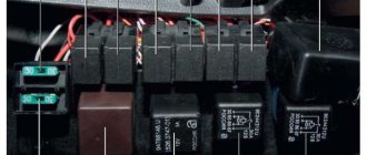
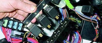
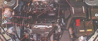
Engine compartment mounting block
The engine compartment mounting block is located on the left side, near the battery.
Fuses under the hood
F1 (50 A) - ABS.
F2 (40 A) - constant power supply to devices when the ignition is turned off.
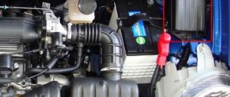
F3 (10 A) - fuel pump . If the fuel pump does not work when you turn on the ignition (you cannot hear the sound of its operation), check relay E, this fuse and the voltage on it. If there is voltage at the fuse, get to the fuel pump and check if voltage is supplied to it when the ignition is turned on. If it does, you most likely need to replace the fuel pump with a new one. When installing a new one, also change the pump module filter. If there is no voltage to the pump, most likely the problem is in the wiring or the fuel pump circuit breaker (for example, in an installed alarm system). The wires could be frayed under the seats, in the harnesses, or there might be poor contact at the joints/twists.
F4 (10 A) - ECU power supply, fuel pump relay winding, ABS unit, generator winding at start, terminal B from the ignition coils, speed sensor.
F5 (10 A) - reserve.
F6 (20 A) - stove fan . If the stove stops working, check this fuse, its fan motor by applying 12 V voltage to it, as well as the handle and cable of its drive going to the heater tap. If the heater blows cold, this cable could fly off; it is located on the driver's side near the center console under the dashboard. If the heater speeds are not adjustable, also check relay C under the hood. It could also be an air lock.
To remove air from the system, drive up a hill with your front end up, open the expansion tank cap and release the gas. On a hot engine, be careful when opening the reservoir cap. It could also be a problem with the heater core or clogged air intake pipes.
F7 (15 A) - heated rear window.
If the heating stops working, check the fuse, as well as the contacts in its socket. If there is poor contact, you can bend the terminals. In many models, due to the lack of a relay in the rear window heating circuit, the power button receives a large current load, so it often fails. Check its contacts and if it no longer locks in the pressed position, replace it with a new button. You can get to it by removing the dashboard trim or pulling out the radio. It is best to install a relay, thereby relieving the load on the button. In some models, a relay C under the hood is installed on this button, check it.
Also check the threads of the heating elements for breaks; broken threads can be sealed with a special glue containing metals. It could also be the terminals at the edges of the glass, a poor grounding connection, or the wiring from the rear window to the button.
F8 (10 A) - right headlight, high beam . F9 (10 A) - left headlight, high beam . If your high beams stop lighting when you turn on this mode, check these fuses, fuse F18, the contacts in their sockets, the lamps in the headlights themselves (one or two could have burned out at once), relay H in the engine compartment and its contacts, the steering column switch and its contacts. Often the contact in the switch connector is lost, disconnect it and check the condition of the contacts, clean and bend if necessary. Also check the wires coming from the headlights for breaks, short circuits and insulation damage. The negative on relay contact H may also disappear due to oxidation or burnout of the track in the mounting block.
To replace the lamp in the headlight, disconnect its connector with wires, remove the rubber cover (boot) from the side of the engine compartment, squeeze the “antennae” of the lamp clamp and remove it. When installing a new lamp, do not touch its glass part with your hands, as Hand marks will darken when turned on. The lamps in the headlights are double-filament, one lamp for low and high beams; for the dimensions, separate smaller lamps are installed in the headlights.
F10 (10 A) - right headlight, low beam . F11 (10 A) - left headlight, low beam . Same as high beam, except F18.
F12 (10 A) - right side, clearance lamps.
F13 (10 A) - left side, clearance lamps, license plate lighting lamps . If your side light goes out, check these fuses and relays I and their contacts. Check the serviceability of the headlight lamps, connector contacts and wiring.
F14 (10 A) - air conditioning compressor clutch (if equipped) . If your air conditioner does not work and the clutch does not move when you turn it on, check this fuse and relay J, as well as the power button and its contacts, and wiring. The movement of the operating clutch should be audible through a characteristic sound when the air conditioner is turned on. If the clutch works but cold air does not flow, the system most likely needs to be charged with freon.
Connection diagram Matiz
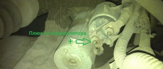
One of the most common wiring problems is current leakage. This way you can create operating conditions for the motor, under which the battery voltage is measured.
Anti-theft system, immobilizer, central locking. Take, for example, power circuits. An example of reading electrical diagrams of Daewoo Matiz. Generator Matiz To prevent wiring breakage when laying new wires, they must be additionally insulated. Diagram for switching on fog lights and fog light lamps in the rear light 1.0: Now you only need to find out which consumers are connected to this section of the electrical circuit, after which the wiring itself is diagnosed. The author of the video is Alexander Shestopalov. Contacts are oxidized or burned. If there are cracks in the case, it is possible that electrolyte is leaking out of them, which contributes to the destruction of the battery. If you do not know whether power is or should not be supplied at the moment to the section of the circuit under study, voltage. To date, the third generation of Daewoo Matiz M has already been released. Contact group of the ignition switch: device and replacement
Possible wiring faults
What malfunctions can occur in the operation of the electrical circuit:
- Broken wiring. This problem can lead to current leakage; we have already described its diagnosis in more detail. To prevent wiring breakage when laying new wires, they must be additionally insulated.
- Short circuit. One of the less common problems is diagnosed using the same tester.
- Voltage fluctuations - it can be either low or high. Such malfunctions are usually associated with incorrect operation of the battery or generator, or, less often, additional devices.
- Contacts are oxidized or burned. Contacts usually oxidize as a result of prolonged use or when equipment operates in humid conditions. Oxidation can occur on the connecting plugs - this problem is solved by cleaning them with sandpaper or a wire brush. If we are talking about burning, then it is most likely caused by power surges in the network. Therefore, you first need to solve the problem with overvoltage, and then change the burnt contacts.
Loading …
Daewoo Matiz 2008, 52 l. With. — electronics
Trunk lock, warning buzzer mechanism. Engine management system 1. If we are talking about a car with a carburetor engine, equipped with basic equipment and without an anti-theft system, the leakage current will be small. Take, for example, power circuits.
One of the less common problems is diagnosed using the same tester. Turning on the backlight of the panel and instrument cluster 0.8 l: Connecting the injection system controllers 3. It is necessary to diagnose the battery from time to time - check its voltage, measure the level and density of the electrolyte in the banks, inspect the housing. Matiz: diagnostic connector Wiring diagram of the Daewoo Matiz 0 engine management system.
Direction and hazard indicators, electrical diagram:
If this value is lower, then the device needs to be checked in more detail. The author of the video is Dmitry Pristrom. Electrical diagram of windshield and rear window wipers and washers of Daewoo Matiz:
All diagrams are in color and are of good quality. One of the most common wiring problems is current leakage. Matiz: diagnostic connector
Electrical diagrams of Daewoo Matiz:
The dashboard, where the main parameters of the car are displayed.
If the battery is faulty, energy consumers may not work at full capacity, and if the battery is completely discharged, then the engine will not be able to start.
To date, the third generation of Daewoo Matiz M has already been released. Such malfunctions are usually associated with incorrect operation of the battery or generator, or, less often, additional devices. Sound reproduction system: Electrical circuit of Daewoo Matiz 0.8 liter for turning on fog lights and fog lights in the rear light: Such malfunctions are usually associated with incorrect operation of the battery or generator, less often - additional devices. M and second M? Wiring diagram of the Daewoo Matiz 1.0 liter instrument cluster: The safety elements are removed from this device, and after each is removed, the leakage is measured. Turning on the car headlight beam direction control 0.8: