Fuse location
For those who urgently need to see the location of the fuses, here is a table.
| Fuse number and color (current strength, a) | protected circuit |
| f1 (10) red | electronic engine control unit (battery circuit) |
| f2 (10) red | side lights, license plate lights |
| f3 (10) red | airbag (if installed) |
| f4 (20) yellow | high beam lamps in headlights |
| f5 (10) red | low beam lamp and electric corrector (if installed) of the left headlight |
| f6 (10) red | low beam lamp and electric corrector (if installed) of the right headlight |
| f7 (30) green | fuel pump, injectors |
| f8 (20) yellow | Turn signal lights, hazard warning lights, brake lights, anti-lock brakes (abs) (if equipped) |
| f9 (30) green | windshield wiper and washer |
| f10 (10) red | electric drive of the hatch cover of the fuel tank filler pipe, abs (if the system is installed) |
| f11 (10) red | air conditioning compressor activation relay (if air conditioning is installed) |
| f12 (30) green | Cooling fan motor (low speed) |
| f13 (20) yellow | instrument cluster, clock, cigarette lighter, warning buzzer, alternator, reverse lights, rear window defroster switch and relay |
| f14 (30) green | Cooling fan motor (high speed), horn |
| f15 (30) green | interior lamp, clock, trunk lamp, electric antenna (if installed) |
| f16 (10) red | power windows (if installed) |
| f17 (10) red | car radio (circuit from ignition switch) |
| f18 (30) green | car radio (battery circuit), electric trunk lock, heated rear window, door lock system (if installed) |
| f19 (30) green | heater fan motor |
| f20 (30) green | fog lights |
Control relays for Daewoo Nexia electrical system
Activation of automotive equipment with a high load current (starter, radiator fan, generator) is performed through electromagnetic relays. In Daewoo Nexia, the main control relays are also located in the mounting block:
| Relay no. | Purpose | Marking | Installation location |
| K1 | Radiator fan motor control (high speed) | 90244312U | External side of the fuse box |
| K2 | Turn signal control | 96312545 U (495.3747-01) | |
| K3 | Fuel pump activation | 90191753U | |
| K4 | Front and rear PTF | 90244312U | |
| K5 | Side lights | 90229206 U | Inside of the fuse box |
| K6 | Front headlights | 90229206 U | |
| K7 | Radiator fan motor control (low speed) | 90229206 U | |
| K8 | Air conditioning compressor control | 90229206 U | |
| K9 | Horn activation | 90229206 U | |
| K10 | Low beam headlights (when high beams are on) | 90229206 U | |
| K11 | Warning signal (buzzer) | 96208850 | |
| K12 | Heater impeller motor control | 90244312U | |
| K13 | Activating the ignition system | 90244312U | |
| K14 | Adjusting the windshield wiper speed | 94788146 | |
| K15 | Rear window heating activation timer | 96116223 |
Fuse box in Nexia
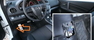
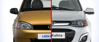
Fuses on Nexia are responsible for the safety of electrical appliances. When a short circuit occurs, the fuse burns out first, thereby protecting the electrical appliance. The fuse box diagram for Nexia 8kl and 16kl are identical and for Nexia n100 and n150 the blocks are also interchangeable. Every self-respecting motorist should have such a diagram at hand. Also, replacing fuses should be done with the engine turned off. The Nexia has a double fuse box; the main fuses and relays are located on the outer visible side, and the remaining relays are located on the reverse side.
To differentiate between each other, fuses come in several colors. Each color has an amp rating.
Red – 10 Amps Blue – 15 Amps Yellow – 20 Amps Green – 30 Amps
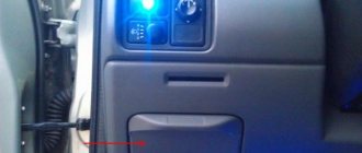
Why does the ignition switch contact group get hot?
First you need to remove the contact group. You can see the numbers on the contact group (see photo):
As you can see, there are only 5 contacts per kg of the ignition switch:
“15a” – stove fan
“Kb” (“Ka”) – radio tape recorder
R - rare on rare 6-pin kg
By turning the key we close the following contacts:
Initial key position “I”: closed “30”+”R”
Initial position of the key “I” + the key is recessed into the ignition switch: “30”+”R”+”Ka” closes
Position “II”: “30”+”Ka” are closed
Position “III” is closed “30”+”Ka”+”15a”+”15″
Starter position: closed “30”+”50″+”15″+”Ka
Why is the contact group burning out so quickly? I hope no more questions arise. All consumers of the car pass through this thing (see photo below), this is the whole problem, to solve it you need to unload the currents using a relay.
The main sources of consumption arise when contacts 30 and 15 are closed, so they need to be unloaded from this current. Installing an unloading relay would be the right option, so you can forget about the problem of burnout of the contact group on the Nexia.
Fuses used in Nexia
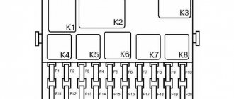
Location and purpose of fuses
(Click on the fuse you are interested in and find out what it does)
| RELAY 1 | 10A | 10A | f3 15A | 20A | 10A | 10A | RELAY 3 |
| 30A | 20A | 30A | f10 30A | f11 10A | f12 30A | RELAY 4 | |
| RELAY 2 | f13 20A | f14 30A | f15 20A | f16 30A | f17 10A | f18 30A |
Find out which fuse is responsible for what below.
- Fuse F1 Electronic engine control unit (ECU) - 10A
This fuse is responsible for powering the brain; if you remove this fuse, the car will not start.
- Fuse F2 Tail lights and license plate light—10A
If your license plate lights and side lights do not work, check this fuse.
- Fuse F3 The fuse was a waste of time, but in some models. — 15A
Also a fuse for the brain, but in most cars there is an empty space here.
- Fuse F4 High beam - 20A
The fuse is responsible for the operation of both high beam bulbs at once, so if the high beam does not light, then check this fuse. If neither the right nor the left high beam headlight lights up, then the reason is most likely in the fuse; if it doesn’t light up on one side, then the light bulb has burned out.
- Fuse F5 Low beam on the left side and left electric headlight adjustment - 10A
Low beam light with electric beam direction corrector, if your corrector does not work and the low beam does not shine, then check the fuse
- Fuse F6 Low beam on the right side, right headlight range control - 10A
Same as f5, but on the right side of the car
- Fuse F7 Fuel pump (fuel pump in the gas tank) - 30A
The fuel pump has a 30 Amp fuse; it is not recommended to install a larger one.
- Fuse F8 Hazard warning light, side turn lamps (turn signals) - 20A
The hazard light may short out the light, if this fuse is overheated, then check the hazard light or turn signals
- Fuse F9 Windshield wipers - 30A
If the windshield wiper doesn't work, it's not a fact that it's a fuse, but it's worth checking
- Fuse F10 Fuel filler neck (fuel door lock actuator) - 10A
In winter, a common problem is that the hatch does not open; if you press the button too much, most likely the electric motor will fail, but before that, check the fuse
- Fuse F11 air conditioning compressor (relay) - 10A
According to the pinout of the fuse diagram on the Nexia, there is a fuse for the air conditioner; if there is no air conditioner, there is no fuse.
- Fuse F12 Radiator cooling fan (low speed) - 30A
An important fuse, always check it to avoid problems with engine cooling.
- Fuse F13 Instrument panel, cigarette lighter, horn, glove box light - 20A
If this pre knocks you out, it means there is a short circuit somewhere. As soon as this fuse burns out, you will immediately understand that the instrument panel will go out and the cigarette lighter will stop working.
- Fuse F14 Nexia cooling fan (maximum speed) - 30A
Always keep the fuse intact so that lack of cooling does not damage the engine.
- Fuse F15 Interior light bulbs, radio antenna - 20A
If the light in the cabin does not light, then the fuse or light bulb is to blame. Check the fuse first
- Fuse F16 Power windows - 30A
If not a single window regulator works, then the front one is burnt out. They usually burn out in winter.
- Fuse F17 Radio - 10A
If the radio doesn't work, look at it
- Fuse F18 Trunk lock drive, central locking, battery-powered radio - 30A
The trunk does not respond to the opening button, and the central locking and radio are silent? It's a blown fuse.
RELAY 1 turn signal
Blower Motor RELAY 2
RELAY 3 fuel pump
If you want to learn more about the fuel pump relay, I recommend reading our article.
RELAY 4 fog lights
How to replace it yourself?
Below we will tell you how to remove and change safety devices and the unit itself.
Replacing fuses
You can remove and change parts like this:
- Turn off the ignition in the car and open the hood. The negative cable must be disconnected from the battery terminal.
- Get inside the car and find the mounting block, remove the plastic protective cover.
- Find the part that needs to be removed and replaced. If the problem lies in the performance of the fan or heating system, then it is not a fact that the reason lies precisely in the fuses. But these details must be checked first. Find the fuse according to the diagram and evaluate its condition. If the element burns out, the fusible thread located inside the part will be damaged. Usually it breaks or burns out. If you notice a defect on the plastic body of the device, it has melted, then this can indicate not only the failure of the part, but also problems in the electrical network. Fuses usually blow due to a short circuit. If this happens, you need to determine the cause of the voltage surges by testing all sections of the circuit or contact a professional electrician. In some cases, a visual inspection does not reveal a failed fuse. A part may look intact, but in fact it is inoperable. When you find a failed fuse, you must remove it using tweezers located inside the block.
- Instead of the blown part, install a new fuse that will correspond to the failed one. We are talking about the numbers indicated on the body of the elements. After installing a new fuse, check the operation of the electrical equipment.
- To remove the relay, proceed in the same way. Identify the failed part, then dismantle it by hand, pulling it towards you. The relay must be removed carefully so as not to damage the socket itself. To diagnose the performance of a part, we recommend installing a known working element instead of a failed one.
- When the replacement steps are completed, replace the plastic cover and connect the negative terminal of the battery.
Photo gallery
Photos of the fuse replacement process are shown below.
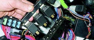
1. Remove the protective cover from the block
2. Find the failed part
3. Remove the fuse and change it
Replacing the block
There is nothing complicated about replacing the mounting block:
- Turn off the ignition and disconnect the terminals from the car battery.
- Remove the cover from the block and remove each safety element and relay in turn. Before removing, we recommend taking a photo of the device so that later you can quickly install all the parts in place.
- There are locks on both sides of the block on the side of the safety elements. They need to be pryed off with a screwdriver.
- Pull the device towards you and disconnect the connector with wires from it. Please note that Nexias of different years of manufacture may use the same blocks, but the plugs for connecting the wires on them will be different. Please consider this nuance when purchasing.
- Connect the connector with wires to the block and install it in place.
- Place all fuses in their sockets and reconnect the battery terminals. Check the functionality of the equipment.
Consequence of untimely repair of a unit
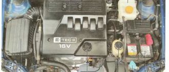
But, if the reasons for the malfunction of the electric fan are not identified in time, and their consequences can be very diverse. So, let's look at this issue in more detail:
- Overheating the engine, especially in the summer, can lead to the engine boiling.
- Consequently, the next consequence is deflection and deformation of the cylinder head, which will entail failure of the gaskets and some internal elements.
- A further consequence may be that coolant enters the cylinders of the main power unit, which can cause water hammer. In this case, the engine will no longer have to be repaired, since even an experienced engine repair mechanic will tell you to change the unit completely.
As you can see, a petty problem can cause you trouble and cost you a considerable amount of money.
Wiring diagrams
Using the following wiring diagram, you can determine the locations of connectors and ground contacts, which can cause interruptions in the operation of devices when they are loosened.
Electrical connectors are marked in yellow and begin with the letter X. Ground wires and body ground contacts are marked with blue dots and numbered.
Ground contacts
1 - in the central part of the steering column 2 - near the battery 3 - not used 4 - on the top of the engine cylinder block 5 - in the trunk 6 - under the driver's seat B - direct contact of the assembly housing with the car body.
Unload the contact group of the ignition switch on the Nexia
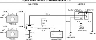
To unload using a relay, you need to purchase the necessary materials in advance, namely, we will need:
A starter relay from a VAZ-2108 (30 A) or even better from a VAZ-2110 (50 A), cost about 100 rubles.
Relay block – 50 rub.
Female terminals for relays (4 pcs) – 5 rub.
Red wire 0.5 m long – 15 rubles.
Black wire 0.5 m long – 15 rubles.
Screw terminal (1 piece) – 2 RUR.
The terminals on the contact group that need to be unloaded are shown in red:
The following is a schematic diagram of the relay:
BEFORE unloading, diagram of connection and operation of the contact group on Nexia:
Connect the relay to the contact group as indicated in the diagram. Scheme for unloading the contact group through a relay:
Using the same scheme, you can install another relay in parallel. After this unloading, you will extend the service life of the contact group and avoid melting of the wiring and burnt plastic in the car interior. Suddenly, if one wire going to “30” heats up, then leave the old wire per kg, and run a new wire from the battery to contact “30”.
Your headaches regarding the contact group will go away, since now the entire load passes not through the pitiful contacts, but through the unloading relay.
By the way, I almost forgot, if you detect melting of the contact group, be sure to replace it with a new one, so I recommend that you read our article about kg. (See Article number of the ignition switch contact group on the Nexia).
ps Share the publication with a friend Nexiavod, so as not to forget how to relieve the contact group on the Daewoo Nexia.
Theme Options
Display
- Linear view
- Combined view
- Tree view
I'm wondering why 15 heats up and 30 stops. and before that I drove normally for 4 years without unloading and so on
Good afternoon The other day my contact group burned out. At first I thought that the contact group itself was closed. I installed a new original one. Then I realized that the problem is not in the contact group, but in the wiring. Then I didn’t know that you could relieve the wiring burden by installing a relay. Yesterday I went to the service center and they installed two 70A unloading relays. The wiring stopped heating up. But now these two relays, after about ten minutes, crack so much that you can’t even lift your finger. I went to the service center because... I paid 1100, but the reason for not heating was not eliminated. The service center told me that it is normal for the relays to get hot. I argued and argued with the service for a long time. As a result, I agreed to go to another master tomorrow. The relay starts to heat up when you turn on the headlights. Can anyone tell me why before everything was fine with the wiring, but now everything has started to heat up!?
It depends on what the relay is from. There are starter ones, they warm up and something else. I got 2*30 from the market, that’s fine. That's what my PTF relatives thought, but they're worth it.