Today, every car, regardless of type, is equipped with special protection for all electrical systems. This protection is called a fuse. They are installed so that in the event of a short circuit or malfunction, the system can turn off via a fuse, thereby protecting itself from breakdown. Fuses are used for every electrical circuit, from a small light bulb to an engine's ignition system. More important engine systems are equipped with special relays, they protect various pumps, electric motors and other powerful sources of electricity consumption.
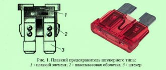
The fuse is a small structure consisting of a plastic casing with a fusible element inside. If a short circuit occurs, the thin contact melts under the influence of current, which interrupts the electric current. The simplest electrical fuse is a thin copper wire inserted into a circuit. If the upper limit of the supplied current increases, the contact begins to melt and interrupts the flow of electricity. Here there is a description of all fuses and relays for VAZ 2113, 2114, 2115 models of injection and carburetor types, old and new models.
Interpretation of fuses and relays of injection models
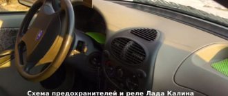
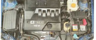
The main electrical fuse module 2114-3722010-60 is located under the front engine compartment. This arrangement allows for quick access to all electrical systems of the car.
Block location
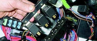
Please note that the location of the electrical fuse module may depend on the type of equipment and year of manufacture of the vehicle. As a rule, this is the upper right part of the engine compartment, under the front windshield. The mounting block is made of plastic in the form of a rectangular box. To protect against accidental opening, the box is equipped with special latches. To open the module, you need to snap off the two protective brackets and lift the top plastic protection. Under the cover are all the main control relays and electrical fuses of the vehicle.
To quickly remove the fuse, special plastic pliers are located on the plastic protection cover. With their help, you can very easily get any element. You need to grab the top edge of the plastic case with pliers and carefully lift the element.
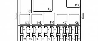
For the convenience of the user, on the top plastic cover there is a complete diagram, made in the form of a schematic image, which shows all the electrical fuses and relays indicating the current strength (A).
Fuse and relay diagram for injection models
Table 1. Explanation of fuses and relays 2114-3722010-60
| № | Current, A | Explanation of fuses |
| F1 | 10 | Rear fog lights, rear fog light indicator lamp |
| F2 | 10 | Turn signals and turn signal breaker relay. Alarm system. Hazard warning lamp |
| F3 | 7,5 | Interior and luggage compartment lighting systems (interior lamp, luggage compartment lamp, ignition key illumination). Brake brake lamp, on-board computer backlight lamp. Engine control lamp |
| F4 | 20 | Rear window heating control. Portable lamp connection socket |
| F5 | 20 | Relay for monitoring and turning on the sound signal. Cooling system engine switch fuse and relay |
| F6 | 30 | Control and relay switching on electric windows |
| F7 | 30 | Electric motor control - heating system, interior heater, windshield washers, headlight cleaners. Interior cigarette lighter, glove box lamp. Turn on the heated rear window. |
| F8 | 7,5 | Turning on the right fog lamp |
| F9 | 7,5 | Turning on the left fog light |
| F10 | 7,5 | Side light for the left side body, indicator light for turning on the side lights (on the display), lamps for illuminating the license plate and engine compartment, illumination lamp for switches, cigarette lighter, heater control levers. Instrument lighting switch. |
| F11 | 7,5 | Right side body marker light |
| F12 | 7,5 | Front right low beam headlight |
| F13 | 7,5 | Front left low beam headlight |
| F14 | 7,5 | Front left high beam headlight. Light indicator lamp. |
| F15 | 7,5 | Front right high beam lamp. |
| F16 | 15 | Body turn signals, relay-breaker for turn signals and hazard warning lights. Control relay and reverse lamps, indicator lamps for the on-board instrument control system, lamps for oil pressure, handbrake activation, brake fluid level, battery charge. On-board computer, engine generator winding. |
| F17-F20 | Spares | |
| № | Relay circuit | |
| K1 | Headlight cleaners | |
| K2 | Turn signals and hazard warning lights | |
| K3 | Windshield wiper | |
| K4 | Monitoring the serviceability of brake light lamps and side lamps | |
| K5 | Window lifters | |
| K6 | Sound signal | |
| K7 | Heated rear window | |
| K8 | High beam headlights | |
| K9 | Low beam headlights | |
Recommendations for care and maintenance
- Buy original fuses. Domestic or foreign, it doesn’t matter;
- Install strictly in accordance with amperage ratings. Unacceptable with lower or higher current strength. In the first case, this will lead to damage to the module, in the second - to breakdown of the unit, which is attached to the fuse;
- Carefully check the quality of fixation of terminals and limit switches on the board. If loose, tighten and press with pliers. A spark can cause a fire and melting occurs;
- If moisture gets in or condensation forms inside the mounting block, remove the cover, dry it, and if necessary, blow it with a stream of compressed air.
Carry out preventive and diagnostic work in the fuse box with the battery terminals removed in order to prevent a short circuit in the circuit.
The average service life of fuses is 40 – 60 thousand km. The service life of foreign analogues is 10–15% longer. Before replacing, read the instructions and get advice from service station specialists.
Decoding fuses and relays of block 2114-3722010-18
VAZ-2114, 2115, 2113 cars of the first models with a carburetor have certain differences in the fuse module.
Old style block fuse and relay diagram
Table 2. Decoding of fuses and relays of block 2114-3722010-18
| № | Current, A | Explanation of fuses |
| F9 | 7,5 | Right rear fog lamp |
| F8 | 7,5 | Left rear fog lamp |
| F1 | 10 | Front headlight cleaners at the moment of switching on, wiper contacts, headlight washer switch valve, headlight wiper switch relay contacts |
| F7 | 30 | Front headlight wipers during operation, winding of the relay for turning on the wipers, fuse for the interior heater, windshield washer, gearbox and timing controller for the rear window wiper, valves for turning on the front and rear washer, relay (winding) for turning on the engine cooling system, relay for turning on the rear window heating, glove box lighting, rear window heating control lamp |
| F16 | 15 | Turn signal indicators and activation of hazard warning lights in turn mode, indicator control lamp, reversing lights, gearbox and relay for activation of windshield washers, generator winding (at startup), control lamps for brake fluid, oil pressure, carburetor flap, hand brake. "STOP" display lamp, voltmeter and coolant temperature indicator |
| F3 | 10 | Interior lighting and rear brake light |
| F6 | 30 | Power windows, power windows on/off relay |
| F10 | 7,5 | License plate lights, engine compartment lamp, warning light on the dashboard (exterior lighting), instrument panel lights, cigarette lighter light, heating lever lights |
| F5 | 20 | Relay for turning on the cooling system fan (electric motor), sound signal. |
| F10 | 7,5 | Left front marker light Left rear marker light |
| F11 | 7,5 | Right front headlight, right rear |
| F2 | 10 | Hazard warning lamp, turn signals and hazard warning relay. |
| F4 | 20 | Rear heated glass, heating on, portable socket, cigarette lighter in the cabin |
| F15 | 7,5 | Front right high beam |
| F14 | 7,5 | Front left high beam Light switch |
| F13 | 7,5 | Left low beam |
| F12 | 7,5 | Right low beam |
| № | Relay circuit | |
| K1 | Headlight washers | |
| K2 | Hazard and turn signals | |
| K3 | Windshield wipers | |
| K4 | Monitoring the health of lamps | |
| K5 | Windows | |
| K6 | Sound signal | |
| K7 | Heated rear window | |
| K8 | High beam headlights | |
| K9 | Low beam headlights | |
Electrical diagram of VAZ 2115 - 20 cars (left half):
1 – headlights; 2 – fog lights; 3 – air temperature sensor; 4 – electric motor of the engine cooling system fan; 5 – blocks connected to the wiring harness of the ignition system; 6 – engine compartment lamp switch; 7 – block for connection to a single-wire type audio signal; 8 – sound signal; 9 – washer fluid level sensor; 10 – front brake pad wear sensors; 11 – oil level sensor; 12 – generator; 13 – engine compartment lamp; 14 – coolant temperature indicator sensor; 15 – starter; 16 – battery; 17 – relay for turning on fog lights; 18 – coolant level sensor; 19 – brake fluid level sensor; 20 – reverse light switch; 21 – windshield wiper gearmotor; 22 – oil pressure warning lamp sensor; 23 – block for connecting to the rear window washer electric motor; 24 – windshield washer electric motor; 25 – instrument cluster; 26 – mounting block. Conventional numbering of plugs in blocks: A - block headlights; B — electric fuel pump block; C — blocks of the mounting block, ignition switch, windshield wiper gearmotor; D — interior lamp
Source
Starter, ignition, rear fog lamp relay
In order to carry out quick checks and repairs, the ignition system relay is installed under the front dashboard of the car, behind the hood release handle. It is located just below the central dashboard. The module is closed with a plastic plug, which must be opened slightly to test for functionality.
Starter, ignition, rear fog lamp relay
Next to the indicated relay, there is a similar one for the rear fog lights and the starter.
The main task of the relay when igniting is to reduce the applied load to the contacts. When the engine starts, the relay turns off some electrical circuits in the vehicle system. The system is used not only in injection, but also in carburetor engines.
In the event of a malfunction or malfunction in the ignition system, it is necessary to monitor the operation of the relay. For this purpose, open the box and carefully remove the desired element. It is attached using contacts to special grooves. The first thing to do is look at the oxidation of the contacts, if necessary, clean them with a soft cloth or treat them with a special liquid.
To check functionality, you need to use a regular multimeter. We connect to incoming connections and check the numbers. If there is no short circuit when current is applied, it means the element is not working. Replacement is carried out in a similar manner. It is necessary to use a standard element with the number of amperes indicated on the housing.
Checking the electrical circuit
Problems occur when the electrical circuit of the audio signal is disconnected. To find the cause, you need to check the entire electrical circuit: wires, connectors. The figure shows the electrical circuit of the horn from the mounting module to the steering wheel, where the signal button is located.
The electrical diagram is also available in the vehicle registration certificate. Oxidation or weakening of contacts leads to disruption of the electrical conductivity of the connectors. Therefore the signal does not turn on. Failure of insulation in wires causes short circuits and blown fuses. It is necessary to check the electrical circuit, all its connectors with a multimeter and troubleshoot:
- Find out the reason for the blown fuse and eliminate it.
- Clean oxidized contacts.
- If necessary, connectors and wires should be replaced.
The picture shows how the horn contacts are checked.
Important : you can work with the battery connected, but with the ignition off. Don't neglect safety measures.
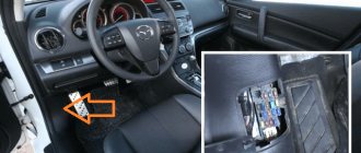
Front fog lamp relay
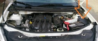
Front fog lights are not standard equipment on the model and are equipped depending on the configuration. The relay itself (if there are fog lights) is located in the engine compartment on the left mudguard.
Front fog lamp relay
Important! To access the relay, you must remove the battery! Without performing this manipulation, it will be difficult to remove and check its functionality.
Replacing a faulty element is very simple. You need to take a Phillips screwdriver (with a short handle), unscrew the bolt securing the relay to the car body, and check the element for malfunction. If it fails, we buy a new one and put everything in the reverse order.