Lada Vesta 2022 - 2022, 2022 2021 is a sedan or station wagon. The SV Cross modification, presented as a new generation crossover, also began to be produced. Regardless of the model type, the installer and fuses of the Lada Vesta remain the same. They differ slightly in the type of configuration.
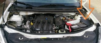
The machine contains 2 blocks of fusible protective elements and the same number with a relay. One of them can be found inside the car, and the second in the engine compartment. The selection of fuses in them differs depending on the role being protected by the electrical circuit. A detailed diagram and its explanation can be seen below.
Block in the cabin
The 2017-2018 Vesta modification contains the largest number of fuses and relays. Most of them are responsible for the safe operation of electrical circuits of devices inside the cabin, as well as those that control the vehicle’s electronics. A comfortable ride and driving safety depend on them.
You can find this block to the left of the dashboard, just below the level of the steering wheel. The lid is indicated by special plastic clips. Below it is a diagram describing its contents.
Review of Manufacturer Prices
| Name/article | Price in rubles |
| Housing cover Lada Vesta 8450007436 | From 300 |
| Jcase | From 180 / piece |
| Mini | From 140 / piece |
| EMM-T4 231A03142 (Renault) | From 170 / piece |
| PF895652A2 (Japan) | From 220 / piece |
*price indicated as of March 28, 2019.
Conclusion
Installing new power modules requires careful attention on the part of the technician. It is unacceptable to violate the current range. The exact data for each of the fuses is indicated in the operating instructions for the technical device. If difficulties arise, contact service station specialists for help.
Vesta fuse box diagram
The set of elements depends on the location of the installer.
Under the hood.
| Fuse | Power, A | What protects |
| F60 | 70 | EURU – electric power steering |
| F61 | 30 | Heated rear window |
| F62 | 40 | ESP |
| F63 | 15 | Air conditioner clutch |
| F65 | 25 | ESP |
| F66 | 5 | AMT Controller - Transmission |
| F68 | 70 | Likewise |
| F69 | 15 | Controlling the A/C clutch relay and relay box |
| F70 | 60 | K30S |
| F71 | 60 | battery |
| F72 | 60/70 | battery |
| F73 | 10 | Sound signal |
| F74 | 5 | Reversing light switch |
| F75 | 60 | Heated windshield |
| F76 | 10 | Alarm horn relay |
| F78 | 10 | Power supply for oxygen sensors, purge valve |
| Adsorber, timing valve | ||
| F79 | 40 | Cooling Fan Relay/Relay Box |
| F80 | 5 | Heated windshield relay coil |
Relay
| Number | Power | What is he responsible for? |
| K21 | 30 | Heated windshield 1 |
| K22 | 30 | Heated windshield 2 |
| K23 | 30 | Starter |
| K24 | 20 | Sound signal |
| K25 | 20 | Alarm sound |
| K27 | 20 | Main relay KSUD |
| K28 | 20 | Air conditioning compressor clutch |
| K29 | 40 | Cooling Fan |
In the cabin.
| Circuit breakers | Power, A | What protects |
| F1 | 15 | Steering column switch right, washer |
| F2 | 30/5 | left steering column switch, non-lux/lux |
| F3 | 10 | Left high beam (non-luxury version) |
| F4 | 30/5 | not luxury/luxury |
| F5 | 15 | Seat heating |
| F6 | 7,5 | Right dimensions |
| F7 | 10 | Left dimensions |
| F8 | 5 | Rear fog lights |
| F9 | Z | Right turn signal in the mirror |
| F10 | 5 | AMT robotic gearbox selector |
| F11 | 10 | Low beam on the left (in non-luxury configuration) |
| F12 | 15 | BCM Controller (Turn Signals) |
| F13 | 10 | BCM controller (self-powered) |
| F14 | 10 | Turning off the brake pedal |
| F15 | 5 | Power supply for rain and light sensor, headlight range control |
| F16 | 5 | Turning off the brake pedal |
| F17 | 5 | Lighting for the glove compartment, trunk, sills |
| F18 | 3 | Left turn signal in the mirror |
| F19 | 10 | Low beam on the right (in non-luxury configuration) |
| F20 | 5 | Heated exterior mirrors |
| F21 | 15 | BU SNPB |
| F22 | 5 | instrument cluster |
| F23 | 5 | instrument cluster |
| F24 | 5 | ERA GLONASS, radio |
| F25 | 5 | ESP9.1 controller |
| F26 | 15 | Power supply to fuel pump module |
| F27 | 5 | Power supply for parking sensors |
| F28 | 5 | EURU controller (electric power steering) |
| F29 | 10 | Power supply for trailer lighting |
| F30 | 5 | ERA GLONASS controller |
| F31 | 5 | ERA GLONASS controller |
| F32 | 10 | K15M Bus Power (Engine Compartment) |
| F33 | 5 | Window control |
| F34 | 5 | Power supply for steering angle sensor, steering wheel button block |
| F35 | 5 | Driver's door switch block |
| F36 | 15 | Radio, diagnostic connector |
| F37 | 7,5 | Right stop lamp |
| F38 | 7,5 | Left stop lamp |
| F39 | 10 | Daytime running lights in non-luxury configuration |
| F40 | 10 | High beam (non-luxury version) |
| F41 | 20 | 12V socket (power supply for additional devices), cigarette lighter fuse for Lada Vesta |
| F42 | 20 | BCM controller (VTR bus power supply) |
| F43 | 20 | BCM Controller (Door Locks) |
| F44 | 30 | Window lifters |
| F45 | 30 | Cabin heating fan |
| F46 | 30 | windshield wiper (switch power) |
| F47 | 25 | EMM controller (PDS, lBS, lGO) |
| F48 | 30 | EMM controller (windshield wiper) |
| F49 | 25 | EMM controller (PTF, ZPTO, license plate) |
| F50 | 25 | EMM controller (lDS, PBS, PGO) |
Relay under the dashboard.
| Number | Power, A | What is he responsible for? |
| K1 | 70/50 | Power supply for lighting/seat heating (in luxury configuration) |
| K2 | 30 | Reserve |
| K3 | 30 | Heated rear window |
| K4 | 30 | Front windows |
| K5 | 40 | Interior heater fan |
| K6 | 30 | Rear window lift |
| K7 | 20 | Fuel pump module |
| K8 | 20 | ACC (12V socket power supply) |
Cigarette lighter fuse for Lada Vesta
The cartridge cigarette lighter insert of the FJ1720A Jcase type with a height of 16 mm is numbered F41 and is designed for 20 A. In some versions, its number is F50 in the interior unit. You can learn more about the element from the video:
Vesta radio fuse
The insert number 41 of the interior unit is responsible for the tape recorder. Its power is 20 Amps.
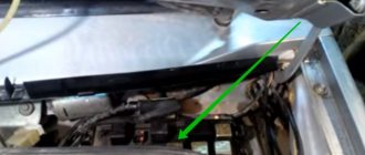
Vesta signal relay and fuse: where is it located?
The horn protection is number 73 and is located in the engine compartment. Power - 10 A.
Vesta starter fuse and relay
The additional one is under the hood and is designated as K23.
Gasoline pump
The 26 x 15 Ampere fuse in the cabin unit is responsible.
Fuses and light relays
There are 2 inserts for low beam lighting, the right and left ones are F11 and F19. They are located inside and the power of each is 10 A.
PTF fuse
The 5 A relay F8, which can be found in the cabin unit, is responsible for protecting the fog lights. The connection occurs via a pulse relay.
Trunk lighting
The fuse is F8, with a power of 5 A. It can be found in the interior block.
Number plate illumination
Answers F49 at 25 Amps.
Button backlight
There is no separate fuse for this task.
Glove compartment lighting
Fuse F8 for the interior unit is intended. Power - 5 Amperes.
Heated seats: where is it located?
The protection of this electrical circuit is controlled by 15 A fuse F5.
Heater fuse
F45 30 A internally.
DRL
Fuse F39 is designed for 10 A.
Heated glass
Two fuses are responsible: F61 for heating the rear, and F75 for the front. Both are rated at 30 A and are located under the hood.
Wiper relay
Located in the central body electronics unit or additional installer (luxury equipment). You can often notice a relay by the fact that it clicks. To get rid of clicks, the block is often covered with soundproofing material.
Generator voltage regulator relay
Article number 120a 8450006900 on Vesta is 1 pin single-contact. It can be used to connect a DVR. The price of such a device is approximately 20 thousand rubles.
Cooling Fan
The relay is located under the hood, where it is designated K29. There is also a fuse responsible for it, number F79 with a power of 40 A.
parking lights
Fuses F6 and F7 in the passenger compartment are responsible for protecting the electrical circuits of the right and left dimensions. In the first case, the power is 7.5 A, and in the second - 10 A.
Generator
There are 2 elements with catalog numbers F71 and F72. Both are 60A.
Running lights
The same fuse is responsible for their protection as for the DRLs.
ABS
There is no separate fuse.
Cruise control
Absent.
Reverse
Absent.
Charging relay
The Valeo generator installed on Vesta is additionally installed.
Main relay
Located under the hood and designated as K27.
Windshield washer
The motor fuse is designated F1 and is rated at 15 A. Its place is in the interior unit.
Airbags
The fuse is not included in the factory configuration.
Relay holder block 314 for Lada Vesta
Responsible for the starter and has 4 contacts.
Reviews
| № | Positive |
| 1. | Georgy Nikolaevich , 42 years old (drive2.ru): the car has been three years old since purchase, I haven’t made any investments, only scheduled maintenance. The fuses are all standard, nothing has been changed. |
| 2. | Mikhail , 48 years old (prom.ua): in two years I replaced two power modules once. I didn’t contact the service, I limited myself to my experience and skills. |
| 3. | Sasha , 38 years old (autotoday.com): There are no complaints about the standard power modules yet, the car is only a year old, but I heard that you can install a unit from Renault Duster, Logan of the second generation. |
| 4. | Kirill , 45 years old (rozetka.ua): mileage 75,000 km, only recently replaced five power modules with new ones. I believe that a resource of 75,000 km is more than enough for domestic transport. Of course, there is still a long way to go to reach foreign brands, but this is progress. |
| 5. | Petrovich , 44 years old, (avtoflit.com): I bought the car second-hand, good condition, five years old. I didn’t do anything to the power system, the units are operating normally. |
| 6. | Nikolaevich , 45 years old, (autotoday.com): I am satisfied with the quality of manufacturing and assembly of the Lada Vesta, no comments. I fix minor damage myself. |
| 7. | Vasilievich , 41 years old, (drive2.ru): the car is four years old, only recently replaced three relays - breakers in the engine compartment. Good build quality Lada. |
| Negative | |
| 8. | Nikiforovich , 49 years old (prom.ua): problems with the power system began after buying the car. I repeatedly contacted the service station due to burnt-out power modules. The problem is still not resolved. |
| 9. | Nikolai Semenovich , 46 years old, (avtoflit.com): I do not recommend standard fuse blocks for the Lada Vesta. If possible, replace with new ones from Renault Duster, Logan of the second generation. |
| 10. | Vyacheslav Petrovich , 47 years old, (drive2.ru): the car is new, but the weak points are inherited from previous generations. |
| 11. | Stanislav Vasilyevich , 39 years old, (autotoday.com): after two years of operation, the car began to crumble in the literal sense of the word. The build quality is still raw and needs improvement. |
Related link:
Review of the dashboard of the Lada Vesta car.
Schematic layout
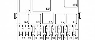
In the interior mounting block you will see the following picture:
Interior mounting block
On a note!
In the lower right corner there are spare fuses for the Lada Vesta.
Schematically the block looks like this:
Schematic location of fuses Explanation of spare fuses Explanation of spare fuses Explanation of spare fuses
Relays that are present in the cabin:
Symbols for the snout in the cabin Body connector Layout of buttons on the steering wheel
Causes and solutions
The first problem and the second problem can only be encountered by a beginner who has this first car and has not yet read the instructions for it. The fact is that the standard connection of the stereo system implies its operation only when the ignition is turned on. That is, I got into the car, started the engine (or simply turned the key in the lock), and turned on the music. This is done to save battery charge. But if you are not satisfied with this situation, then contact electricians who will quickly make the device “independent”.
The next problem is a barely noticeable indication on the display. This happens exclusively in cold weather, at sub-zero temperatures. The problem is easily solved by warming up the interior and within 15 minutes everything returns to normal. It’s hard to call this a malfunction; most likely, this is a feature of the displays.
It happens that when you briefly press the power button, the device does not respond. In such a situation, the advice is simple - hold the key for a few seconds. Perhaps these are isolated cases associated with a specific device, but this still happens sometimes.
In some situations, the car radio may have a software failure and not respond to attempts to turn it on. To do this, a reset is provided on the front panel. Next to the power button there is a hole in which the reset key is located. To activate it, you need to gently press it with something sharp and hold it for a few seconds. Sometimes this helps to “reanimate” the radio.
LADA VESTA. DIAGNOSTIC CARDS OF THE M86 ENGINE CONTROLLER 21129 EURO-5
Map A-4
Checking the main relay and power circuit
Circuit Description
When the ignition is turned on, voltage from the ignition switch is supplied to contact “X1.1/A5” of the controller. The controller, through contact “X1.1/J3”, turns on the main relay, through which the supply voltage is supplied to contacts “X1.1/L3” and “X1.1/K3” of the controller, as well as to sensors and some controlled devices (canister purge valve , injectors, relays).
Description of checks
1 Voltage is supplied to contact “X1.1/A5” of the controller from the ignition switch.
2 The diagnostic device shows the voltage of the on-board network, determined by the controller from the voltage at contacts “X1.1/L3” and “X1.1/K3”. It should not differ by more than 1 V from the battery voltage.
3 There should be battery voltage present at the contacts of the harness block to terminals “85” and “30” of the relay. If power is present on both contacts, the light of the probe connected to ground should light up when you touch them.
4 The previous test determined the presence of voltage at the contact of the harness block to terminal “85” of the relay. This test monitors the main relay control circuit, which must be closed to ground by the controller.
5 The serviceability of the main relay is checked.
The reason for the incorrect value of the on-board voltage, determined by the controller from the voltage at contacts “X1.1/L3” and “X1.1/K3”, may be a short to ground in the power supply circuits to the relays and actuators, as well as incorrectly connected anti-theft devices.
Map A-5
Checking the electrical circuit of the fuel supply system.
Circuit Description
When the ignition is turned on, the controller turns on the electric fuel pump relay and the electric fuel pump starts working. If there are no reference pulses from the crankshaft position sensor (the engine is not running), the controller turns off the electric fuel pump through
2 s after turning on the ignition.
Description of checks
The sequence corresponds to the numbers on the card.
1 The electric fuel pump is forced on.
2 Check the presence of +12 V voltage at the contacts of the electric fuel pump relay.
3 When the ignition is turned on and the engine is cranked, the controller should turn on the electric fuel pump.
Injector ramp assembly for engine 21129:
1 — injector ramp; 2 — fitting for monitoring fuel pressure; 3 - nozzle; 4 - sealing ring; 5 — nozzle clip
Video on the topic “Checking the main relay and power circuit of the Lada Vesta”
ECU repair. No spark. VAZ car won't start. The fuse is on.
https://youtube.com/watch?v=eSW_JQyzuuc
Lada Granta - Mounting block (fuses and relays)
Lada Granta problems with relay