Fuse and relay block VAZ 1111 OKA
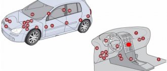
- Repair manuals
- Repair manual for VAZ 1111 (Oka) 1988-2003.
- Fuse and relay box
8.1.1 Fuse and relay box You will need a key “8” Before starting work, disconnect the wire from the “–” terminal of the battery.
The fuse box is located under the instrument panel to the left of the steering column and is secured with two nuts. EXECUTION ORDER 1. Remove the cover of the unit... 8.1.2 Removing and installing the fuse box You will need a key “8” Before starting work, disconnect the wire from the “–” terminal of the battery. The fuse box is located under the instrument panel to the left of the steering column and is secured with two nuts. EXECUTION ORDER 1. Remove the cover of the unit... 8.1.3 Checking and replacing the relay You will need an 8-mm wrench and a screwdriver. Before starting work, Unscrew the nuts securing the fuse box and move it to the side (without disconnecting the wire ends from it) - see subsection 8.1. 1. Relay for turning on the starter, low and high beam headlights, heated rear window...
↓ Comments ↓
1. Description of the car
1.0 Description of the car 1.1 Appearance 1.2 Engine compartment 1.3 General data 1.4 Technical characteristics 1.5 Passport data 1.6 Doors 1.7 Hood lock 1.8 Luggage compartment 1.9 Increasing the volume of the luggage compartment
2. Safety requirements
2.0 Safety requirements 2.1 Safety requirements 2.2 Preparing the car for operation 2.3 What you need to have in the car 2.4 Operating the car during the warranty period 2.5 Running in the car 2.6 Preparing the car for departure 2.7 Checking the wheels 2.8 Checking the coolant level 2.9 Checking the oil level in the engine crankcase
3. Maintenance
3.0 Maintenance 3.1 Checking the tightness of the cooling system 3.2 Checking the tightness of the cooling system 3.3 Checking the tightness of the power system 3.4 Checking the tightness of the brake system 3.5 Replacing the coolant 3.6 Checking the functionality of the thermostat 3.7 Replacing the engine oil and oil filter 3.8 Replacing the air filter element 3.9 Removing and installing the air filter filter
4. Car storage
4.0 Vehicle storage 4.1 Maintenance during storage 4.2 Removal from storage
5. Chassis
5.0 Chassis 5.1. Front suspension 5.2. Rear suspension
6. Steering
6.0 Steering 6.1 Removing and installing the steering wheel 6.2 Replacing the intermediate steering shaft 6.3 Replacing the steering shaft bearings 6.4 Replacing the tie rod end and protective boot of the ball joint 6.5 Removing and installing the steering mechanism 6.6 Replacing the steering rod
7. Brake system
7.0 Brake system 7.1. Front brake mechanism 7.2. Rear brake mechanism 7.3. Brake system drive 7.4. Parking brake
8. Electrical equipment
8.0 Electrical equipment 8.1. Fuse and relay block 8.2. Generator 8.3. Ignition system 8.4. Lighting and alarm 8.5. Instrument cluster 8.6. Switches and switches 8.7. Windshield wipers and washers 8.8 Replacing the electric radiator fan motor of the cooling system
9. Body
9.0 Body 9.1 Removing and installing the front buffer 9.2 Removing and installing the rear buffer 9.3 Replacing the front fender 9.4 Removing and installing the radiator trim 9.5. Hood 9.6. Side door 9.7. Rear door 9.8. Rear view mirrors 9.9. Seats 9.11. Heater
10. Engine and its systems
10.0 Engine and its systems 10.1 Installing the piston of the first cylinder to the TDC position of the compression stroke 10.2 Adjusting the clearances in the valve drive 10.3. Camshaft drive belt 10.4. Replacement of engine seal parts 10.5. Cylinder head 10.6 Removing and installing the power unit 10.7. Engine repair 10.8. Lubrication system 10.9. Cooling system 10.10. Power system 10.11. Exhaust system
11. Transmission
11.0 Transmission 11.1. Gearbox 11.2. Clutch 11.3. Front wheel drives
12. Applications
12.0 Appendix 12.1 Appendix: Tightening torques for threaded connections 12.2 Appendix: Fuels and lubricants and operating fluids 12.3 Appendix: Basic data for adjustments and control 12.4 Appendix: Filling volumes 12.5 Appendix: Lamps used in the car 12.6 Appendix: Layout of rolling bearings 12.7 Appendix : Oil seals 12.8 Appendix: Service book 12.9 Appendix: Vehicle electrical diagram
Relay st/och. 722.3777-02 (VAZ 2101-07, 21213, 1111 “Oka”, ZIL 4331) with adjustable pauses "Energomash"
show all photos
Relay st/och. VAZ 2101-07, 21213, 1111 “Oka”, ZIL 4331 with adjustable pauses "Energomash"
2 Other products from the same category:
- Relay st/och. 380 rub. View
- Relay. 380 rub. View
Customers who bought this product also bought:
- Autotester. 150 rub. View
- Relay. 650 rub. View
- Additional. 250 rub. View
- Eyeglass case. 350 rub. View
- Lubrication. 150 rub. View
- Indicator(for 60 RUR. View
- Automotive. 450 rub. View
- Defrost. 50 rub. View
- Contactless. 410 rub. View
- Signal. 280 rub. View
- More details
Relay st/och. VAZ 2101-07, 21213, 1111 “Oka”, ZIL 4331 s
regul. pauses "Energomash"
Windshield wiper breaker with pause adjustment 722.3777-02.
1 Installing the windshield wiper switch.
1.1 Disconnect the wiring harness from the steering column wiper switch by opening the 6-pin connector, which is located behind the instrument panel or inside the steering column housing. 1.2 Connect the terminal blocks of the windshield wiper breaker into the resulting gap in the harness. 1.3 Using a connector, connect the free wire of the breaker to the wire connecting the steering column switch to the washer motor. This is one of the wires of the 2-pin block of the steering column switch, the potential of which, when the washer is turned on, changes from +12 V to 0 V or vice versa (depending on the specific brand of car). 1.4 Using the breaker mounting hole, install it in a convenient place on the car. The windshield wiper switch is ready to operate.
2 Pause adjustment.
2.1 Set the windshield wiper mode switch to the “Intermittent mode” position - the standard pause of the windshield wiper operation will be set (about 5 seconds between sweeps of the blades). 2.2 To change the pause, move the switch to the “Off” position and, after maintaining the required pause, switch to the “Intermittent mode” position. The new pause value will be set. The pause range is from 0.5 to 45 seconds. 2.3 The pause can also be changed in another way: move the switch to the “Continuous mode” position and, during the first stroke of the brushes, back to the “Intermittent mode” position. The pause value will be equal to the time interval from the last stroke of the brushes until the moment of switching to the “Continuous mode” position. The pause can be changed at any time by repeating step 2.2 or 2.3.
3 Other modes.
3.1 When water is supplied, the movement of the brushes begins with a delay of 0.5 seconds (allows a sufficient amount of water to accumulate on the windshield before the first stroke of the brushes).
3.2 After supplying water, the brushes make three strokes.
Article rating:
Where is the eye fan relay? Link to main publication
Fuse box diagnostics (video)
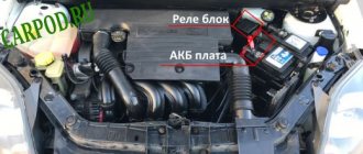
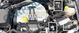
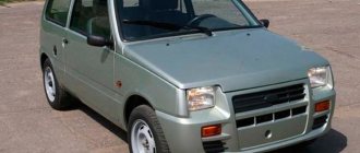
We present to your attention the electrical circuits of equipment for the VAZ-1111, also known as OKA, 1988-2003. 4-seater hatchback of a particularly small class with a transverse engine and front-wheel drive. Production of the Oka began in 1989 at the Volzhsky Automobile Plant. The engine is a two-cylinder with a displacement of 650 cc, in 1997 it was increased to 750 cc. volume. Currently, the production of Oka cars has been transferred to the Kama Automobile Plant, as well as the Serpukhov Automobile Plant. In addition to the basic models KamAZ-11113 and SeAZ-11113, manual control options are available for disabled people. Due to its very low price, it is of interest for export. This small car was developed at the Volzhsky Automobile Production Plant at three factories - VAZ, KamAZ and SeAZ - in a disabled version, and has been produced since 1990.
Electrical diagram for OKA
1 - side turn signal repeater 31 - exterior lighting switch2 - front turn signal 32 - fuse block3 - headlight 33 - fog light circuit fuse4 - cooling fan motor 34 - rear window heating relay5 - horn 35 - cooling fan motor relay6 – fan motor activation sensor 36 – parking brake warning lamp relay interrupter 7 – windshield washer motor 37 – rear window wiper and washer switch 8 – spark torque sensor 38 – rear window heating switch 9 – battery 39 – rear fog lamp switch 10 – starter 40 - control lamp for covering the carburetor air damper11 - switch 41 - hazard warning switch12 - spark plugs 42 - ignition switch13 - ignition coil 43 - ignition relay14 - generator 44 - heater fan motor15 - coolant temperature indicator sensor 45 - fuel level indicator sensor16 - control sensor low oil pressure lamps 46 – lamp switch in the door pillar 17 – socket for a portable lamp 47 – instrument cluster 18 – windshield wiper relay 48 – windshield wiper switch 19 – brake fluid level sensor 49 – windshield washer switch 20 – brake signal switch 50 – horn switch 21 – windshield wiper electric motor 51 – headlight switch 22 – carburetor solenoid valve 52 – turn signal switch 23 – reverse light switch 53 – parking brake warning lamp switch 24 – starter switch relay 54 – interior lamp 25 – low beam headlight relay 55 – control switch carburetor air damper cover lamps 26 – headlight high beam relay 56 – rear door glass washer motor 27 – hazard warning and turn signal breaker relay 57 – rear light 28 – cigarette lighter 58 – rear fog light 29 – heater fan switch 59 – license plate light 30 – additional heater electric motor resistor 60 - rear door glass heating element 61 - rear door glass wiper electric motorA - order of numbering of contacts in the connecting blocks
Additional relays
Depending on the configuration and design, additional relay placement is possible.
Scheme
Purpose
- Hazard warning and direction indicator relay (494.3747 / 2105-3747010-01) - located behind the instrument cluster.
- Front wiper relay (RS-514 (2101-5205150)) - located under the upholstery, left side panel.
- Parking brake warning lamp relay (RS-492 (2101-3803150)) - located behind the instrument cluster, next to the turn signal relay (see point 1).
- Additional relay (90.3747-10 / 113.3747-10 / 2105-3747210-20).
- Ignition relay (90.3747-10 / 113.3747-10 / 2105-3747210-20) - secured with a self-tapping screw from inside the instrument panel.
Division by function
As for functions, all electrical equipment is divided into systems that perform specific tasks:
- Take part in the operation of the engine;
- Ensure traffic safety;
- Create comfortable conditions;
There are also systems that are aimed at maintaining the functionality of the electrical circuit itself.
Systems responsible for engine operation
The ignition system takes part in the operation of the power unit and its task is to generate a spark in the engine cylinders to ignite the air-fuel mixture. The components of this system are a switch, a spark torque sensor, a coil and spark plugs. The system is turned on using the ignition switch. All of these components are connected by one circuit, the diagram of which is shown below:
The second system related to electrical equipment and working with the engine is the starting system. To start the engine, a power electric motor is used - a starter, controlled from the same ignition switch. Its scheme is as follows:
The cooling system fan is also related to the engine.
Systems responsible for safety and comfort
Electrical equipment that ensures traffic safety includes:
- Light and sound alarm (turn signals, brake lights, reversing lights, sound signal);
- Main light (headlights, PTF);
- Heaters, glass cleaners and washers;
These devices are combined into several systems. Below is the power supply diagram for only one of them - the turn signals:
Since the Oka is a budget car, there are not so many electrical appliances that create comfortable conditions for the driver. These include a stove (which includes an electric fan motor), an interior lamp and a cigarette lighter.
Note that the stove, in addition to creating convenience, also affects traffic safety - it heats the windows in winter.
Since devices responsible for traffic safety and comfort are not always in demand, they are turned off by default and are activated using switches.
The on-board network also includes a battery recharging system, that is, a component whose task is to maintain the functionality of electrical equipment. Its connection diagram is as follows:
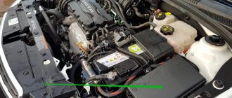
Electrical equipment Oka
The VAZ-1111 and 11113 Oka are equipped with all the necessary electrical equipment necessary to ensure traffic safety and create minimally comfortable conditions for the driver and passengers. All electrical appliances installed on a small car are connected by a single electrical network.
The on-board network used on Oka is 12-volt, DC, single-wire. The role of the second wire is performed by the car body and a number of components and mechanisms - the power plant, gearbox.
Preventive measures
The main measures to ensure reliable operation of the electrics of Oka cars:
- At least once every six months, clean the outer part of the battery case and check the electrolyte level (on serviced models). At the same time, it is necessary to recharge the battery using a special device. If the vehicle is rarely used, it is recommended to disconnect the terminals.
- When carrying out repair work, you should monitor the position of the wires, avoiding damage to the insulating layer. Wires passing near moving elements must not come into contact with them under any circumstances.
- It is not recommended to turn on devices with high current consumption (audio system, high beam headlights, etc.) with the engine off. This will cause the battery to drain faster.
- Do not use homemade elements to repair electrical circuits. All used parts and assemblies must comply with the standards laid down by the designer when developing the car.
- It is recommended to carry spare fuses, relays and lamps with you. This will allow you to make minor repairs if necessary.
- When carrying out repair work that requires the use of welding, it is necessary to disconnect the harnesses from the battery and generator. On machines equipped with an injection engine, it is recommended to disconnect the connector from the control unit.
How to identify a blown fuse
It is quite simple to assess the condition of cylindrical type modules, as well as knife type ones. In both cases, a melting element is laid in the center of the fuse.
As soon as the current exceeds the permissible value, the plate instantly melts, opening the contacts. A small black spot forms, which is evidence that the part is faulty.
The module is removed from its seat using special plastic tweezers. In life, an accessory is often lost, so it is practiced with your fingers. After replacement, we put the power terminals on the battery, start the engine, and test the system.
Electrical diagram of VAZ-1111 with symbols
Electrical diagram of VAZ-1111, part 1
Electrical diagram of VAZ-1111, part 2
Electrical diagram of VAZ-1111, part 3
Electrical diagram of VAZ-1111, part 4
List of elements indicated in the diagram:
- 1 — side turn signal repeater located on the front fender;
- 2 — front direction indicator;
- 3 — head lighting device;
- 4 - electric motor used to drive the radiator cooling impeller;
- 5 — warning sound signal (horn);
- 6 - temperature sensor, which ensures that the cooling system impeller is turned on;
- 7 — motor for driving the front window washer pump;
- 8 — distribution sensor of the ignition system;
- 9 — lead-acid battery;
- 10 - electric motor for starting the engine;
- 11 — ignition system controller;
- 12 — spark plugs installed in the cylinder head;
- 13 — ignition system coil;
- 14 — alternating current generator;
- 15 — liquid temperature indicator in the cooling jacket;
- 16 - control sensor that determines emergency oil pressure in the engine;
- 17 — connector for installing a portable lamp;
- 18 — windshield wiper operation controller;
- 19 — indicator sensor of the fluid level in the hydraulic brake drive system;
- 20 — brake pedal position limit switch;
- 21 — motor for driving the trapezium wipers on the front window;
- 22 - electromagnet located in the carburetor valve;
- 23 — limit switch responsible for the operation of the reverse gear signals;
- 24 — starter controller;
- 25 — headlight control relay (low beam);
- 26 - similar unit for high beam;
- 27 — controller of direction indicators and emergency lights;
- 28 — cigarette lighter socket;
- 29 — speed switch for the heating system motor;
- 30 - additional resistor that determines the rotation speed of the heater fan impeller;
- 31 — external lighting operating mode switch;
- 32 - fuse block;
- 33 — additional protective element for fog lamps;
- 34 — rear window heating control controller;
- 35 - start relay, necessary for the operation of the cooling system fan;
- 36 — control relay for the control indicator of the position of the parking brake lever;
- 37 — control of the rear window cleaning system (together with the washer);
- 38 — glass heating operating mode switch;
- 39 — rear fog light button;
- 40 — indicator of the open starting valve in the carburetor;
- 41 — alarm control button;
- 42 — ignition switch;
- 43 — distribution relay of the ignition system;
- 44 — heating fan impeller motor;
- 45 — indicator of the amount of gasoline in the tank;
- 46 — interior lighting switch located on the central pillar;
- 47 — instrument cluster;
- 48 — front wiper control;
- 49 — turning on the windshield washer;
- 50 — horn control button;
- 51 — lever for changing the operating modes of the head lighting;
- 52 — direction indicator control lever;
- 53 — limit switch, responsible for indicating the position of the parking brake lever;
- 54 — interior lighting lamp;
- 55 — limit switch located behind the carburetor choke control button;
- 56 — motor for driving the glass washer pump on the rear door;
- 57 — stern canopy;
- 58 - fog signal, located on the rear of the car;
- 59 — registration plate illumination system;
- 60 — tailgate glass heating threads;
- 61 — stern wiper blade drive motor.
The specified colors of connecting wires correspond to the factory documentation. During repairs, many owners replace sections of the harnesses with cables with insulation of a random color. Because of this, some vehicles have difficulty identifying the wiring.
Diagram of hazard warning lights and direction indicators
- Front direction indicators;
- Ignition switch;
- Hazard switch;
- Turn signal switch;
- Side direction indicators;
- Turn signal lamps in the rear lights;
- Turn signal indicator lamp (in the instrument cluster);
- Relay-breaker for direction indicators and hazard warning lights;
- Fuse box.
Lamp burned out
Naturally, if any light source does not turn on, the first thing that comes to mind is that the light bulb has burned out. The design of car lamps is such that the low beam may indeed be absent, but the high beam remains available. Halogen lamps have two filaments. It is quite possible for one of them to rupture - in this case, the light for which it is responsible will be absent.
To replace the bulb, the services of an auto electrician are not required. It is enough to open the hood with the ignition off, remove the protective box on both sides of the headlight, pull out the contact group, disconnect the spring clips, remove the burnt out bulb and install a new one.
A little subtlety:
The flask should be wiped with alcohol before installation, otherwise it will burn instantly. It is also not recommended to handle the bulb with unprotected hands: there is always some greasy and damp secretions on them, which can damage the light bulb. The best way to do this (replace the lighting) is with a dry cloth or rag.
General scheme
The general diagram of the electrical equipment of the VAZ 11113 is presented below:
1 – turn signal repeater; 2 – front turn signal; 3 – headlight; 4 – el. fan motor with cooling; 5 – signal; 6 – fan switching sensor; 7 – el. washer pump motor; 8 – spark supply moment sensor; 9 – battery; 10 – starter; 11 – switch; 12 – candles; 13 – coil; 14 – generator; 15 – temperature sensor; 16 – oil pressure sensor; 17 – 12 V socket; 18 – windshield wiper relay; 19 – brake fluid level sensor; 20 – brake light switch; 21 – el. windshield wiper motor; 22 – el. carburetor magnetic valve; 23 – reverse light switch; 24 – starter relay; 25 – low beam relay; 26 – high beam relay; 27 – alarm relay; 28 – cigarette lighter; 29 – electric switch. stove motor; 30 – extra electric resistor stove motor; 31 — lighting switch; 32 – safety block; 33 — PTF power supply fuse; 34 – relay for turning on the rear window heater; 35 – electric switching relay. fan motor with cooling; 36 – parking brake control relay; 37 – rear window heater and washer switch; 38 – rear window heater switch; 39 – rear PTF switch; 40 – carburetor suction control; 41 – alarm switch; 42 – ignition switch; 43 – ignition relay; 44 – el. stove motor; 45 – fuel sensor; 46 – lamp switch; 47 – dashboard; 48 – windshield wiper switch; 49 – glass washer pump switch; 50 – signal switch; 51 – light switch; 52 – turn signal switch; 53 – brake light switch; 54 – interior lamp; 55 – carburetor suction control switch; 56 – el. rear window washer motor.
For ease of maintenance and troubleshooting, the wiring connecting the components of electrical equipment is color coded. Connecting devices to wires is carried out in different ways - through blocks, clamping with nuts, using sockets (light bulbs). In all cases, disconnecting the wiring is easy and does not particularly complicate the dismantling of electrical appliances during maintenance.
An electrical circuit combines all components related to electrical equipment. All components can be divided among themselves according to two criteria:
- Purpose;
- Functions performed;
Peculiarity. An electrical circuit is the interweaving of certain sections of power circuits, especially the fuse box. That is, one fuse may be responsible for the operation of electrical appliances that do not interact with each other in any way.
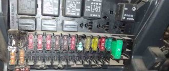
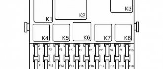
Fuse installation diagram
| Marking | Scheme |
| Fuse (1) / 15 | Stove heater |
| Fuse (2) / 10 | Fan activation sensor |
| Fuse (3) / 5 | Windscreen wipers |
| Fuse (4) / 5 | Carburetor solenoid valve |
| Fuse (5) / 15 | Turn signals. Alarm |
| Fuse (6) / 20 | Tail lights, oil pressure, battery |
| Fuse (7) / 20 | High beam, low beam, dimensions |
| Fuse (8) / 15 | License plate light |
| Fuse (9) / 5 | Power socket, interior lighting |
| Fuse (10) / 5 | Cigarette lighter |
The cost of the original fuse block assembly (hereinafter referred to as the BP) starts from 1,200 rubles. high-quality analogues from 800 rubles.
Disassembly
Disassembling the generator, in general, is not difficult, with the exception of one point - removing the pulley. You can fix the rotor in order to loosen the pulley fastening nut using a special tool. device An alternative removal option is to fix the pulley itself in a vice using elastic attachments (for example, a belt can be placed between the pulley and the jaws).
The general operating technology of the generator is as follows:
- Remove the pulley (using a tool or a vice);
- Disconnect the capacitor wire and dismantle the capacitor itself;
- Unscrew the regulator mount and remove it;
- Unscrew the coupling bolts;
- Use a puller to tighten the front cover;
- Remove the rotor;
- Unscrew the fasteners of the stator leads to the rectifier;
- Remove the stator;
- Unscrew the nuts securing the rectifier to the back cover;
- Remove the rectifier;
After disassembly, all that remains is to remove the front bearing, which is installed in the front cover, for which you need to unscrew the bolts holding the fastening washers together.
Having finished disassembling, we clean all parts and troubleshoot. Some types of faults can be determined visually, but for such faults as breaks and short circuits of the windings, the Oka generator needs to be checked using measuring instruments. For example, to test the regulator, you need a charger with regulated voltage.
This component is checked like this:
- We connect a charger to the output and ground of the regulator, and a 12-volt light bulb (control) to the brushes;
- We apply a voltage of 12 volts, and the lamp should light up;
- We increase the voltage to 15 V (in a working regulator the control should go out);
If the lamp does not light up at 12 V or does not go out at 15 V, the regulator is faulty and requires replacement. As for the stator windings, it is better to entrust their inspection to an experienced auto electrician.
Assembly of the unit is carried out in reverse order
In this case, special attention should be paid to the correct connection of the generator, or rather all its terminals and wires
If an auto electrician determines that the device cannot be repaired, it will have to be replaced with a new one. And what makes the generator suitable for Oka is indicated above.
Common electrical faults
Common problems with electrical equipment on VAZ-1111 and 1113:
- Failure of external lighting devices. A common cause of failure is burnt out lamp filament; the unit must be replaced. If the light bulb is intact, then there may be a defect in the electrical wiring, due to which a short circuit occurs and the fuse fails. The fuse link is replaced with an identical one; it is prohibited to use parts designed for a higher current. It is also unacceptable to install homemade jumpers (“bugs”), as this can cause a fire. If a repeated burnout occurs, it is necessary to check the circuit and eliminate the wiring fault.
- Wire breaks occur at points where the insulation is subject to bending or friction against moving surfaces. An example of such a point is the junction of the door and the body. Damaged areas must be replaced with products made of similar material with an identical cross-section.
- Oxidation of contact surfaces due to moisture or aggressive liquids (for example, battery electrolyte). It is necessary to clean the surfaces down to metal, restoring the transmission of electric current.
- Relay failure associated with burnt contacts or coil breakage. The unit cannot be repaired; it must be replaced with a new one. In the event of a rapid re-failure, the vehicle's electrical system must be checked at a car service center.
- Sudden battery discharge is due to an internal short or current leakage. In winter, a partially charged battery may lose capacity due to low air temperatures. You need to charge the battery and check the condition of the wiring. If necessary, the power source must be replaced.
- Pulsating operation of external lighting lamps with an unusually bright glow indicates a breakdown of the relay regulator on the generator. Repair requires removing the unit and replacing failed components.
- Insufficient battery charge (the warning light does not go out when the engine is running). The cause may be wear on the brushes or commutator, or insufficient tension on the drive belt. The generator needs to be repaired, since the battery charge is enough for 150-200 km during the daytime.
- Poor contact between the ends of the cylindrical fuses and the spring-loaded elements in the mounting block. It arises due to the design features of the unit. Many owners, tired of dealing with the defect, install homemade blocks for knife inserts. Usually a short section from the GAZ-3110 is used, designed for 13 seats. There are self-assembled units designed for fuses and relays.
Photo gallery
The process of installing a new mounting block with blade elements.
Burnt contact of the standard unit
Destruction from local heating is clearly visible
Jumpers on the new block required to reduce the number of insertion locations
Wired unit
Replacing fuses on Oka
The PSU installation process is quite simple and intuitive. At the preparation stage, we check the availability of:
- Collar;
- Heads on "10";
- A new old-style power supply unit (cylindrical type) or a knife type, if the owner decided to upgrade;
- Additional lighting as needed if work is carried out in conditions of limited visibility.
- Place the car on a flat surface, open the driver's door wide;
- We wedge the rear row of wheels with wheel chocks and squeeze the parking brake lever. This is necessary for personal safety during work;
- Open the hood, unscrew the power terminals from the battery to prevent a short circuit in the on-board circuit;
- We snap off the cover from the power supply unit and squeeze the plastic clips on the sides;
- Using a 10mm socket, unscrew the mounting bolts on the sides. We remove the power supply from the seat.
Main malfunctions and why the starter does not turn?
Malfunctions of the Oka starter, as well as the power electric motors of cars, are divided into two categories - mechanical and electrical. The first includes:
- Wear of armature support bushings;
- Damage to gear teeth;
- Jamming of the retractor relay armature;
- Development of splines for the armature shaft;
The most common mechanical failure is wear of the support bushings, which subsequently becomes the cause of other breakdowns. Due to significant wear of the bushings, the position of the armature and, accordingly, the bendix are disrupted. As a result, it is more difficult for the gear to engage, the wear rate of the teeth increases, and they may crumble.
Electrical faults include:
- Breakage of stator windings, armature, solenoid relay;
- Heavy wear of collector plates;
- Critical wear of brushes;
- Closing the windings;
- Burning of “nickels” of power contacts;
To this category of breakdowns you can also add problems with the power circuits of the electric motor and relay.
Turn relay VAZ 2101
Malfunctions of the Oka starter manifest themselves in different ways:
- The starter does not turn on, there are no additional sounds;
- You can hear the activation of the solenoid relay, but the electric motor does not turn;
- The starter rotates, but picks up speed;
- Extraneous sounds are heard when turned on (crunching, grinding);
If such signs occur, the unit should be repaired.
Installation and repair of a starter in an OKA car (VAZ-11111)
All about the features of Nissan x-trail fuses: photos and videos
Like any internal combustion engines of passenger vehicles, the power units of the Oka car modifications 1111, 11113 are started using a starter - a power electric motor with remote control. The task of this unit is to spin the crankshaft to create the necessary conditions for ignition of the air-fuel mixture.
Models, characteristics, location
The designers did not borrow a starter from other VAZ models, but made a new one - for Oka engines. The impossibility of unifying starters for owners of this small car often results in problems, since the “native” starter is not a particularly reliable unit.
It is noteworthy that Oka’s power electric motors were produced by several manufacturers. The most common is the unit with the factory index 39.3708 (KZATE Samara plant), which we will consider in the future. Also, the VAZ-1111 was equipped with Belarusian-made components (1111-3708010-5) and Slovenian ones - AZE-1517.
The main characteristics of model 39.3708 are as follows:
- Power – 0.9 kW;
- Current consumption – 230A;
- Weight – 5 kg;
This unit is mounted on the left side of the engine (in the direction of travel) above the gearbox, and the thermostat housing is located above it. Fixation is carried out with only two fasteners - a bolt and a nut, with which the starter is attracted to the clutch housing. This arrangement is convenient because you can dismantle the unit from the car without removing anything additional.
The starter on the Oka is a commutator electric DC motor. Its main components are:
- Stator with field windings;
- Brush holder (brush assembly) with 4 graphite brushes;
- Anchor;
- Bendix (drive gear with freewheel);
- Solenoid relay with drive plug;
- Lids;
All elements are assembled into a single structure and secured with coupling bolts.
The stator due to the passage of electrical energy through its windings, ensures the emergence of an electromagnetic field. The second magnetic field is created by the armature winding. Electric current is supplied to it through graphite brushes to the commutator, to the plates of which the ends of the armature winding are soldered. The magnetic fields generated around the windings lead to the rotational movement of the armature.
On one side of the armature shaft there are splines on which a bendix is mounted, consisting of a gear and an overrunning clutch. Bendix has the ability to move along the shaft, and due to the spline connection, rotation is transmitted to it.
Symptoms of failure
To check the functionality of the generator, a test lamp is included in its connection diagram. If the device is working properly, the control lights up before the engine starts, indicating that the circuit is in working condition, and after the power unit starts, the light should go out.
It is by the indicator lamp, as well as a number of indirect signs, that a generator malfunction can be identified:
- The signal does not light up when the ignition is turned on, while the other measuring instruments are working. Such a problem may indicate a malfunction of the light bulb itself or an open circuit in its power supply;
- It does not light up and other devices do not work. This may indicate a blown fuse, an open circuit in the instrument panel, or a faulty lock or ignition relay;
- The light glows when the engine is running. This may occur due to breakdown of rectifier diodes, regulator malfunction, short circuit or breakage of stator windings, weak drive tension;
- The lamp works normally, but the Oka generator does not charge (the battery is often discharged). This problem can arise as a result of broken contacts in the wiring suitable for the device, a malfunction of the regulator, a malfunction of the rectifier, broken commutator wires, wear of brushes or slip rings;
- The lamp works fine, but the battery is being recharged (it often boils). Here the reason should be sought in the voltage regulator.
The control lamp allows you to identify mainly electrical faults. As for mechanical breakdowns, they manifest themselves in the form of extraneous noise when the engine is running - hum, squealing, whistling. Often such symptoms are caused by loosening the drive tension. But if adjusting the belt does not eliminate the noise, then you should check the condition of the bearings.
Separation by purpose
By purpose, the equipment is divided into:
- Power supplies;
- Protective means;
- Controls;
- Instrumentation;
- Actuators;
Some circuit components have dual purposes. These include relays, which are both control elements and protective devices.
Power supplies
Power sources include the battery and generator. The battery powers the electricity. devices and ensures their operation when the power unit is turned off. After starting the engine, the on-board network is powered from the generator, which also ensures that the battery is recharged.
Protective components
Protective means prevent burnout of electrical appliances and electrical circuits during short circuits. The main protective elements are fuses. For convenience, all protective elements are collected in one place - the fuse box, which in Oka is located under the front panel on the driver’s side.
Controls
Control elements include all components responsible for turning on, switching and turning off electrical appliances. This category combines the ignition switch, all kinds of switches and switches. Most of these elements are located within direct reach of the driver - on the front panel, steering column. But there are switches that the driver acts on through certain components - brake light switches, a sensor for turning on the choke warning light, etc.
Rain sensor DDA-07
The rain sensor is designed to improve comfort, reduce driver fatigue, increase safety, and increase the service life of windshield wipers and blades when driving in rain or wet road conditions. Suitable for domestic cars - Niva, Classic, Oka.
Rain sensor 722.3777-05 (replacement for DDA-07) replaces the windshield wiper relay for VAZ 2121 / 2131 Niva 4x4, VAZ - 2101-2107, 1111 Oka. The device also has a function for adjusting the pause of the wiper swings in the first position of the wiper lever.
List of cars with which this rain sensor works:
VAZ / Lada: -2101; -2102; -2103; -2104; -2105; -2106; -2107; -2121 / 2131 Niva 4×4; -1111 "Oka".
More details about the applicability of the sensor can be found here.
For models VAZ-2108, VAZ-2109, VAZ-2110, VAZ-2111, VAZ-2112, IZH-2126 (old fuse box), AZLK 2141 “Moskvich”, Chevrolet Niva, “UAZ-Patriot”, UAZ-3160 is used relay DDA-15.
For models VAZ-2108, VAZ-2109, IZH-2126 (new fuse block), VAZ-2113, VAZ-2114, VAZ-2115, Kalina, Priora, and some foreign cars, the DDA-25 relay is used.
Model DDA-35 is used on cars with a built-in electronic wiper relay (control signal - minus).
The DDA-45 model is used on the Lada Granta Lux car with a built-in electronic windshield wiper relay (control signal - plus) and other cars with a similar connection diagram.
The DDA-55 model is used on cars with both positive and negative connections. It has pause adjustment and other advanced functions. Recommended for foreign cars.
Model DDA-65 is similar to DDA-55, but additionally includes a light sensor.
Principle of operation:
The optical sensor is placed on the windshield of the car inside the passenger compartment, so that it is in the operating area of the windshield wiper blades. The DDA uses an infrared ray to check the condition of the glass itself. Depending on the presence of moisture or dirt, the level of the reflected signal will change. Based on this signal, the electronic unit will turn on the windshield wiper. Thus, as soon as water appears on the glass, the wipers turn on. The sensor takes into account the speed of the car (the higher the speed, the more often the wipers operate), as well as the intensity of the rain itself. In case of such an unpleasant phenomenon, when your car is splashed out of a puddle by another car, the sensor will see such a large volume of water already at a distance of 10 cm and turn on the windshield wiper in advance. At the same time, the driver can at any time independently turn on the wipers and adjust the frequency of sweeps with a standard switch.
Installation is very simple and does not require special skills or tools.
The operation of the DDA is not affected by factors such as glass fogging, the presence of fog, temperature, or time of day.
Suitable for all types of glass (tinted, athermal, isothermal), because The sensor automatically adjusts to the transparency of the glass.
Warranty - 1 year.
Option 1: By courier
The time and date of delivery will be confirmed by the manager after registration.
Delivery cost: 300 rub.