In an Audi 80 car in the B3 and B4 body, regardless of the configuration and specific model, there are 2 complementary fuse blocks. Designations are given after the introductory part of the article. They perform various functions, and on-board equipment is connected to them. Thus, the block located in the engine compartment contains power fuses and relays that ensure the operation of large current consumers: fuel pump, headlights, wipers, air conditioning, cooling fan, ignition system, horn, etc. The block located in the passenger compartment (it is often called additional ), is responsible for the operation of devices without which the operation of the car is not comfortable.
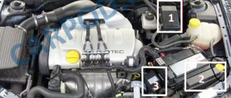
If the electrical equipment of the car is in good condition, then the fuses burn extremely rarely - usually the cause of such a malfunction is the human factor.
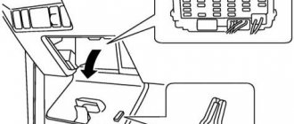
Location of electronic units in the cabin of the Audi 80 90 B3
The Audi 80 90 b3 has two main relay and fuse blocks. One is located in the engine compartment, near the wipers. The second one is under the dashboard in the cabin.
Description
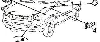
- On-board computer/unit for automatic diagnostics of vehicle systems;
- Electronic fuel injection control unit or Motronic electronic control unit;
- Electronic air conditioning control unit;
- Vehicle position (height) sensor above sea level;
- Electronic ignition control unit;
- Buzzer for switching off automatic transmission mode;
- Air conditioner control panel;
- Power seat power relay.
- Electronic control unit for electric seats;
- Additional mounting block;
- Airbag activation unit;
- Airbag;
- Electronic control unit for automatic transmission;
- Hazard warning light (turn signal) breaker;
- Diagnostic system contact connectors;
- Contact connector for fog lights.
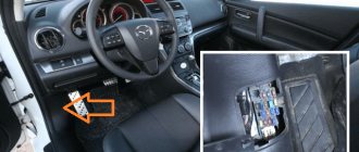
Where to look for the fuse
First, let's look at the heater fuse on the Audi 80. Regardless of which body is relevant for your car, B3 or B4, the location and diagram are the same.
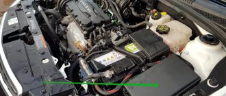
You should look for the block you need in the engine compartment. When you open the hood of your Audi, you will see the fuse box there. You need to look in the area under the windshield. Please note that you may not notice it right away, since the block is covered with a special plastic cover. This is necessary to protect against external harmful influences in the form of debris and moisture.
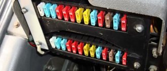
In total, the Audi 80 safety block contains 31 elements, as well as 4 additional components, the so-called spare ones. The location of fuses and relays is relevant for B4 and B3, so the circuit can be considered universal.
Here you will find a special connector. It is used in situations where it is necessary to connect a tester or other diagnostic equipment to check the status, errors and functionality of the on-board computer of your Audi 80.
If we talk about the stove fan we are interested in, it is located at number 17 and has a rating of 30 Amperes. When replacing, use only a similar component of the same rating. It is strictly not recommended to use fuses for more or less amperes.
To avoid any confusion when searching for the right fuse, simply rely on the cover of the fuse block. On the reverse side there are corresponding labels that allow you to understand where which fuse or relay is and what they are responsible for.
There should also be no difficulties with the procedure for replacing a burnt-out element. The work is extremely simple if you follow the instructions and follow the basic recommendations. Replacing a fuse on an Audi 80 is carried out in the following sequence:
- To begin, turn off the engine and raise the hood. Be sure to remove the negative terminal from the car battery to completely cut off the power to the car. It is not necessary to remove and put away the entire battery. It is enough to remove the minus;
- Using a screwdriver, remove the protective cover from the safety block. Flip the cover over to see the layout that applies to your unit. Although there is no detailed description there, the printed symbols make it possible to figure out where each fuse and relay are, as well as what protective functions they perform;
- Also, special tweezers must be attached to the lid. But since the Audi 80 is already quite an old car, the tweezers could get lost over a long service life. You should not try to manually pull out the fuse, as you can easily accidentally damage other fusible elements. It is better to use something like tweezers from a manicure set, or small pliers;
- Remove the heater fan fuse and visually check its condition. If it has melted and become deformed, then the fan definitely does not turn on due to a lack of power, which the fuse has broken;
- Take a similar fuse with the same rating and carefully insert it into the socket instead of the old heater fan protection element.
Fuses and relays in the interior of the Audi 80 90 B3
Description for cars manufactured before 1989
| Relay No. in the picture above | Name |
| 1 | ABS relay |
| 2 | Seat belt warning relay |
| 3 | Interior lighting relay |
| 4 | A/C clutch relay |
| 5 | |
| 6 | Headlight relay |
| 7 | — |
| 8 | — |
| 9 | — |
| 10 | — |
| 11 | — |
| 12 | Reverse current relay (electric seats and rear view mirrors) |
| 13 | Front passenger seat heater relay |
| 14 | Driver Seat Heater Relay |
| 15 16 | Relay for electric sunroof and power windows |
| 17 | — |
| 18 | — |
Description for cars manufactured after 1989
| Relay No. in the picture above | Name |
| 1 | ABS relay |
| 2 | Seat belt warning relay |
| 3 | Interior lighting relay |
| 4 | A/C clutch relay |
| 5 | Windshield wiper/washer relay* |
| 6 | Headlight relay |
| 7 | |
| 8 | — |
| 9 | Automatic Shift Lock Relay |
| 10 | — |
| 11 | — |
| 12 | — |
| 13 | Front passenger seat heater relay |
| 14 | Driver Seat Heater Relay |
| 15 16 | Relay for electric sunroof and window lifts |
| 17 | Anti-theft warning light relay |
| 18 | Reverse current relay (electric seats and rear view mirrors) |
Repair and maintenance book
If you still have questions, ask them in the comments or download the repair and operation manual for the Audi 80 1991-1995: “ “. To view, use the djvu reader program.
There are quite a large number of cars from the AUDI family in operation. They have proven themselves to be reliable, comfortable cars. They are equipped with a large amount of equipment that uses power from the vehicle’s on-board network. To protect against its failure, a fuse box is used. This module is designed to install 28 protective devices, several of which are spare.
To facilitate the detection and replacement of a faulty device, manufacturers adopted a uniform condition for indicating the permissible current with a color code in all Audi units.
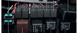
This block is placed in the engine compartment of the Audi 80. In addition to fuse links, electromagnetic relays are installed in it. The main purpose of their installation is to protect the contacts of switches, steering column switches, and other devices from wear and tear due to high current. There are 11 such relays in the module. Some modifications of cars may have wire jumpers instead of electromagnetic relays. Therefore, check the diagram of the fuse links on the cover of your car with the description of the module.
Advice! You cannot install a device with a large rated current value in place of a burnt-out fuse-link.
If this condition is not met, expensive electronic equipment may fail. There have been many cases of electrical wiring fires due to this.
The fuse block diagram of the Audi 80 b3, the diagram of which is shown below, differs from other, later models of this family.
The relays in the mounting module are responsible for connecting the following consumers of the vehicle's on-board voltage:
- Fog lights, tail lights. In the case where there are no fog lights, a wire jumper will be installed;
- Second fan for cooling the power unit;
- Turns on the fan in the engine cooling system after it has stopped;
- Connection module for headlight cleaning system;
- Relay X contact;
- Second fan (relay) for cars with automatic air conditioning system;
- Klaxon;
- Alarm system;
- Intermittent wiper mode;
- Electric fuel pump;
- The first fan in the cooling system.
The Audi 80 b3 fuse box has another module located inside the car. Depending on the modification and configuration, 18 relays can be installed in it. Some of them may not be in demand. They will provide power to the following consumers:
- ABS system;
- Alarm for unfastened seat belt;
- Interior lighting relay;
- Air conditioner clutch;
- Temporarily not in use;
- Head lighting;
- Temporarily not in use;
- Temporarily not in use;
- Temporarily not in use;
- Temporarily not in use;
- Temporarily not in use;
- A relay that supplies reverse current for the electric seats and rear-view mirrors;
- Heated passenger seat;
- Heated driver's seat;
- Electric drive for sunroof, power windows;
- The same consumers;
- Not used;
- Not used.
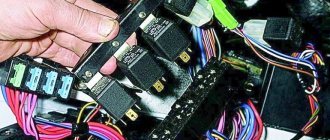
Fuses and relays under the hood of Audi 80 90 B3
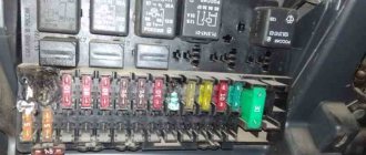
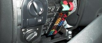
On the removed cover (7) of the central switch, a short form (6) shows the possible location of the relays and fuses. There are also small plastic pliers for disconnecting fuses. Inside the central switch, various relays (1), diagnostic plugs (2), fuses 1–21 (3), and additional fuses 23–32 (4) are visible. Next are four spare fuses (5).
Diagram of the fuse and relay box under the hood of the Audi 80 90 B3
Description for Audi 80, 90 models up to 1989
| № | Elements of the protected circuit |
| 1 | 15A Fog lamps for headlights and rear lights |
| 2 | 15A Hazard Light Interrupter |
| 3 | 25A Horn, brake light |
| 4 | 15A Interior lamps, luggage compartment lamp, Audi 80 90 cigarette lighter fuse, sun visor mirror lamp, on-board computer, radio |
| 5 | 30A Engine Cooling Fan |
| 6 | 5A Lamps for side and parking lights of the right rear lamp |
| 7 | 5A Side light and parking light lamps of the left rear light |
| 8 | 10A Main beam lamp of the right headlight, control lamp for turning on the main beam headlights |
| 9 | 10A Left headlight high beam lamp |
| 10 | 10A Low beam lamp, right headlight |
| 11 | 10A Low beam lamp for left headlight |
| 12 | 15A Instrument cluster, reverse lamps, on-board computer, self-diagnosis system unit, Electronic control unit for the anti-lock brake system, Electronic differential lock control unit |
| 13 | 15A Fuel pump. |
| 14 | 5A License plate, engine compartment and glove box lamps, instrument cluster lamps |
| 15 | 25A Windshield wiper motor, engine cooling fan, electronic air conditioning control unit, turn signal lamps |
| 16 | 30A Heated rear window, heated rear view mirrors |
| 17 | 30A Electric motor of the fan (supercharger) of the interior ventilation system |
| 18 | 5A Electric rear view mirrors |
| 19 | 10A Central locking |
| 20 | 30A Switch (first stage) engine cooling fan, Electronic fan control unit when the engine is running |
| 21 | 25A Rear cigarette lighter |
| 22 | — |
| 23 | 30A Motors for adjusting the driver's seat position, driver's seat position memory unit |
| 24 | 10A Electronic control unit for the KE-Jetronic or Motronic system |
| 25 | 30A Seat heaters |
| 26 | — |
| 27 | — |
| 28 | 15A Electronic control unit for Motronic system |
| 29 | 5A Reserve |
Relay
| Number | Name |
| I | Fog light relay |
| II | Engine cooling fan relay |
| (high speed) | |
| III | Cooling fan relay |
| engine when the engine is not running | |
| IV | — |
| V | Unloading relay |
| VI | Air conditioner relay |
| VII | Horn relay |
| VIII | Automatic transmission relay |
| IX | Windshield wiper and washer intermittent relay |
Description for Audi 80, 90 models from 1989
- Fog lights, rear fog lights 15 2. Hazard warning lights 15 3. Horn, heated seats 30 4. Clock, trunk light, vanity mirror, reading light, socket/cigarette lighter, trip computer, full automatic air conditioning, radio, auto check system (Auto-Check-System) 15 5. Second stage cooling fan speed 30 6. Right tail light, front side light 5 7. Left rear side light, front side light 5 8. Right high beam, high beam indicator 10 9. Left high beam headlight 10 10. Right low beam, right headlight leveling motor 10 11. Left low beam, left left headlight leveling motor 10 12. Instrument cluster, reversing light, Auto-Check-System ), automatic transmission, differential lock, on-board computer, control system, speed control, interior lighting lamp with switch-off delay, electronic thermal switch, operation of the cooling system fan after stopping the engine 15 13. Fuel pump 15 14. License plate lamp, instrument lighting, engine compartment lighting, glove box lighting, automatic air conditioning 5 15. Turn signals, windshield wipers, windshield washer pump, heated windshield washer nozzles, cooling system fan (control unit for turning on the cooling fan after the engine is stopped), air conditioning 25 16. Heating rear window, heated external rear view mirrors 30 17. Fan, automatic air conditioning 30 18. Electrical adjustment of external rear view mirrors, rear window washer (station wagon) 5 15 19. Central locking system, heating of door paint mechanism cylinders, alarm 10 20 The first stage of the cooling system fan, turning on the fan after stopping the engine 30 21. Self-diagnosis / connecting a diagnostic tool 10 22. Free -
The electric beet lifts, electric sunroof and electric seat adjustment are equipped with automatic fuses that automatically switch on again after the fault has been corrected.
- Free - 24. Free - 25. Lambda probe heating 5 26. Trailer socket 30 27. Ignition/injection system 10 28. Ignition/injection system 10 29. Brake light 10 30. 31. Speed control system in combination with automatic gearbox, ABS, differential lock 5 15 32. Ignition/injection system 10
Relay
- Fog light relay;
- Spare;
- Cooling fan relay;
- Headlight washer relay;
- Unloading relay;
- Engine cooling fan relay;
- Horn relay;
- Automatic transmission relay;
- Relay for intermittent operation of the windshield wiper and washer;
- Fuel pump relay;
- Engine cooling fan relay.
Audi 80 B3 operating manuals:
If you have experience with repairs, troubleshooting, or information on this topic, leave your comment below, useful information will be added to the article.
Each electrical device in a car is designed for a specific voltage. The diameter of the supply wire is calculated taking into account this voltage. If the current consumption in a certain circuit, for example, due to the connection of additional consumers, increases, then the supply wire experiences additional load. It may overheat or even burn out if the flow of current is not interrupted in a timely manner. This function is performed by fuses. To avoid complete blackout of the on-board network, each circuit has its own fuse. However, connections to the battery, alternator, starter and ignition switch do not have fuses.
To remove and replace fuses, use the plastic clip that is attached to the cover of the central distribution panel (see illustration 3.0).
If a new fuse blows immediately after installation, make sure that the fuse of the required rating was installed, and not a smaller one. If the rating corresponds, then check individually all consumers of this circuit. Use the appropriate electrical diagram for this. If necessary, disconnect all consumers in the circuit and then connect one at a time. If, when connecting the next consumer, the fuse blows, then this consumer is faulty.
Resistor
A failed heater resistor is a fairly common problem among Audi 80 car owners.
At the same time, fixing such a breakdown yourself is not so difficult. There is no need to go to a car service center and pay someone money for a relatively basic repair. You just need a new resistor, as well as an understanding of the location of the desired object.
It is not difficult to determine that the heater on an Audi 80 does not work precisely because of a resistor failure. A clear sign of such a malfunction is the heater turning on exclusively at speed 4, while fan blowing modes 1, 2 and 3 do not turn on.
Yes, first of all it is recommended to check the condition of the contacts in the control unit, as well as the integrity of the wires. It cannot be ruled out that they are the problem. But if the check did not show any problems in the electrical circuit, then the problem is in the heater resistance resistor. It periodically burns out and therefore needs to be replaced.
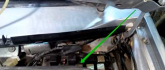
If we talk about the location, you will find the resistor directly on the electric motor of the stove. To access it you will need to open the glove compartment and remove it from the rails. In fact, getting to the resistor is extremely easy if you know how to remove the glove compartment.
You need to disconnect the connector with the wires and remove the resistor from the latches. The resistor fails due to the thermal fuse blowing. It needs to be replaced to restore the functionality of the element.
It's up to the motorist to decide, but Audi 80 owners usually use 2 methods:
- buy a new resistor and install it in place of the old one;
- restore the old resistance resistor through makeshift repairs.
Objectively, the best solution would be to purchase a new element that has a quality guarantee from the manufacturer. But this option is more financially expensive. And since it is important for many to save money, it is worth describing the option of repairing and restoring the resistor.
- Here you can take a piece of wire. But the option is not the best. It is preferable to use a simple 10 Amp fuse;
- Using wire cutters, the old fuse is bitten off, and a new 10-amp element is screwed in its place;
- Using copper wires in a protective sheath, as well as electrical tape, the contacts of the resistor are connected to the contacts of the fuse;
- Next, the assembly is assembled in the reverse order;
- The performance of the heater is checked at all speeds.
The experience of motorists shows that such a repair scheme for the heater resistance resistor on Audi 80 cars has every right to exist. But if in doubt, just buy a new resistor and change it according to the instructions. This is literally 10 minutes of your time.
Although fuses, relays and resistors are small parts of a car, they can play a key role in many issues. Including the performance of the heating system on Audi 80 cars in different bodies.
Moreover, checking the condition of the components considered is quite simple. The automaker has provided convenient access to the fuse box and resistor. Even the heater control unit is not as difficult to disassemble as some might think. A few latches and mounting screws separate you from it.
Control block
Also, one of the reasons for the failure of the heater on the Audi 80 is a breakdown of the control unit. These are the same knobs and buttons with which the driver can configure the operation of the heating system.
To solve the problem with the control unit, it will need to be dismantled. If malfunctions are detected, the unit is completely replaced or repaired. The first option is preferable for a number of objective reasons, although it requires more financial costs.
Dismantling and subsequent replacement of the heater control unit on the Audi 80 in B3 and B4 bodies is carried out in the following sequence:
- Having raised the hood, you should disconnect the negative from the battery in order to eliminate possible risks from contact with the wires of the control unit;
- there are handles on the control panel, to remove which you just need to pull them towards you;
- when the handles snap off, access to 2 screws opens underneath them;
- the fasteners hold the black frame, which should also be removed;
- then access to 4 more screws opens;
- they hold the control unit on themselves;
- By unscrewing the screws, you can dismantle the unit and replace it.
As you understand, assembly is carried out in reverse order. To replace, you will need a similar block that matches the design of your Audi 80. You can use new blocks, or purchase them at car dismantling yards. The second option is cheaper, but you should first make sure that the purchase works.