Lada Priora (Lada Priora) is a general designation for a family of cars produced with sedan, hatchback, station wagon and coupe bodies. The head car of the family was VAZ-2170. Years of production: 2007, 2008, 2009, 2010, 2011, 2012, 2013, 2014, 2015, 2016, 2022 and 2022. During this time, Priora underwent one minor update and a deep restyling ( Priora 2). In this material you will find description of fuse and relay blocks Lada Priora with diagrams and photographs. Let's highlight the fuse responsible for the cigarette lighter.
The design of the blocks and the purpose of the elements in them may differ from those presented and depend on the year of manufacture and the level of equipment of your car (norm, standard, luxury, luxury plus).
How does a car fuse work?
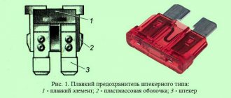
One of the simplest structural elements of a car is a fuse, which consists of two main parts - a plastic body and a fuse-link with contacts. However, despite the simplicity of the design, such details play a very important role. After all, they not only eliminate the possibility of electrical equipment failure, but also prevent the possibility of a fire. It is thanks to fuses that when a short circuit occurs in the electrical circuit or under increased load, the insulation on the wires does not melt, but the fuse-link burns out.
Priora uses flag or plug-type devices. Inside the case there is a plastic insert that has a certain current rating. The fuse housing has a transparent appearance, which is done specifically to visually determine the suitability of the product. Legs protrude from the body - they are also contacts that close the electrical circuit.
The main parameter of fuses is the current strength. The corresponding value for which the element, or more precisely, the fuse link, is designed is indicated on the body. If there is no designation, then you should focus on the color of the case. The case is painted in different colors for a reason, but in order to determine whether a particular fuse belongs to the corresponding current rating. Below is a photo showing the colors and their corresponding current ratings.
Use this information if you find it difficult to determine the fuse rating yourself. Having understood the device and color rating, you should consider the principle of operation of the devices.
In the circuits of various electrical equipment, fuses are installed that have a certain current rating. Electrical appliances consume different currents, and to eliminate the possibility of false operation, devices with the appropriate current rating are used. When a large current begins to flow in the circuit, the wires heat up, but the first thing that heats up is the fuse-link, which is eventually interrupted, thereby breaking the circuit.
The absence of a fuse would in such a situation lead to melting of the insulation, and as a result, shorting of the positive contacts to ground. The result of such consequences is disastrous for the vehicle, as can be seen by looking at the photo below.
Such consequences arise when fuses are installed of the wrong rating or drivers completely neglect the need to use such devices, and in the event of a melted fuse insert, they solve this problem by short-circuiting the circuit with jumpers. This cannot be done, since the result of such rash actions leads in 100% of cases to dire consequences.
Fuses cannot be repaired. There is no need to try to solder the fuse links, thereby restoring the functionality of the products. If the device fails (more precisely, it worked), then it is not suitable for use and must be replaced. Moreover, it is important to install fuses of a similar current rating in the circuit, since neglecting this rule will lead to the following consequences:
- if the fuse is installed with a lower rating than necessary, it will trip more often even for no apparent reason;
- If the product is installed with a higher rating than necessary, then with an increased load in the circuit, the fuse-link will not operate in a timely manner, and the insulation will melt. Every driver understands the outcome and consequences of insulation melting.
Having understood the design of fuses, their operating principle and differences in rating, we move on to considering the devices on the Lada Priora car. Let's consider all possible configuration options for the Priora, indicating all the fuses and relays.
EUR - what is it?
Electric power steering is a kind of electric motor that helps the driver turn the steering wheel with less effort. The EUR is installed on the steering wheel shaft and, when the engine is running, helps to rotate the steering wheel, powered by electrical voltage.
The main task of the ESD in a car is to reduce the force of rotation of the steering wheel by the car driver.
What it consists of:
- Steering shaft;
- Torsion shaft;
- Electrical engine;
- EUR control unit;
- Motor rotor sensor;
- Torque sensor;
- Circuit breakers;
The components of the EUR include the following elements:
- Steering rack;
- Steering wheel;
- Speed sensor;
- Steering cardans;
All these details directly affect the operation of the electric power steering of the Lada Priora.
Where are the fuse and relay blocks located on the Priora?
Before you start checking the fuses, you need to understand their location. On a Priora car, blocks with fuses and relays are located in several places, and therefore we will consider where to look for them.
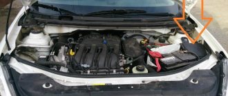
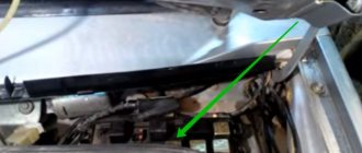
- Engine compartment - there are two blocks here. The first (main) fuse block (without relay) is responsible for the health of the power circuits of devices such as the ECU, cooling fan, generator, EMUR or EUR and others. The photo below shows what this block looks like. It is located under the hood next to the battery.
To find it under the hood, you need to look in the area of the left “glass”. Its location is shown in the photo below. - The engine compartment is a fuse and relay box responsible for protecting the air conditioning system. Naturally, such units are available on Priors, which have an air conditioning system. This block is located near the left “glass” and consists of fuses and control relays. It is important to note that the units differ depending on the type of air conditioning system used on the vehicle. Prioras are equipped with air conditioners of two brands, Halla and Panasonic, and depending on the type, the units differ in the internal arrangement of the elements. The photo below shows where the fuse box and relay for the air conditioning system are located on a Priora.
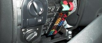
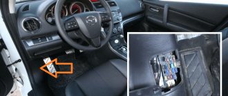
- The car interior - there are also two fuse and relay blocks installed here. The first is located directly under the dashboard on the driver's side. This block contains fuses that are responsible for the electrical equipment on the car, namely, light, sound signal, cigarette lighter, immobilizer, double-glazed windows, etc. The photo below shows where this block is located.
- Inside the car under the center console on the passenger side. Few people know about this fuse and relay block. This block contains fuses that are responsible for the health of the fuel pump, ECU and starter circuits. The relays on this block are responsible for switching the ignition switch and fuel pump circuits. Below is a photo of where this block is located on Priora.
Knowing the places where the fuses and relays are located on the Priora, you can begin to consider the purpose of each element.
This is interesting! Depending on the configuration of the Priora, the fuse and relay blocks, which are located under the dashboard on the driver's side, differ.
Identifying signs of a problem
When the contacts burn out, the driver begins to hear clicks, indicating that the magnet is triggered. At the same time, there is an anchor in the starter, which remains motionless, and even if it moves, it moves extremely slowly. This happens when the contacts, or rather their working surface, are not completely connected, which causes:
- The copper splash is heated;
- The transient voltage begins to rise;
- An air gap immediately begins to appear.
As a result, a dielectric – oxide – appears on the surface. There is only one way you can fix everything. It is necessary to clean the deposits from the deposits that have formed. You can do this work yourself. If the damage is not large, then you can use a diamond file or use a student's eraser. When the device is severely damaged, it is better to replace it completely.
Main fuse box on Priora under the hood: purpose of elements
First, let's examine the fuse box, which is located under the hood of the Priora. The unit is equipped with high-rated fuses, which indicates protection of the power circuits of powerful electrical equipment.
This is interesting! For easier searching, use the Ctrl+F key combination on your computer.
Below is a photo of the block with the corresponding name of the fuses.
- The first 30A green F1 is responsible for protecting the power circuit of the electronic computer system, the fuel pump and the ignition relay.
- The second F2 60A blue color is designed to protect the power circuit of the electric fan of the cooling system, as well as the ignition relay, heated rear window and the double-glazed window controller.
- The third 60A blue F3 is responsible for protecting the cooling fan power supply control circuit, as well as the horn, hazard warning lights, ignition switch, instrument cluster, interior lighting, STOP signal and cigarette lighter.
- The fourth F4 60A blue is designed to protect the generator circuit.
- The fifth F5 50A red color is designed to protect the power circuit of the electromechanical power steering EMUR.
- The sixth F6 60A blue is designed to protect the generator circuit.
To check the suitability of these fuses, they do not have to be removed from the block. To do this, there are open contacts on the front part through which you can ring the elements and make sure that the fuse link is in good condition.
Technical characteristics of the EUR
| Name | Index |
| Rated voltage, (V) | 13,5 |
| Operating voltage, (V) | 10-15 |
| Maximum current, (A) | 55 |
| Current at rest, (A) | 0,5 |
| Moment of resistance at rest, (Nm) | 0,8 |
| Weight, (kg) | 9,3 |
| Operating temperature, (⁰С) | -40…65 |
Fuse box in the interior of a Priora car: basic configuration (standard) without air conditioning
Now let's look at the main fuse and relay block for electrical equipment, which is located inside the car under the dashboard on the driver's side. The photo below shows where the block is located.
To gain access to it, you need to unscrew the three thumbs and remove the plastic decorative trim.
After this we will see the corresponding fuse and relay block of the Priora. Its appearance will vary depending on the type. They come in two versions:
- type 1118-3722010-00;
- DELRHI 15493150.
The difference between them is insignificant, as you can see by looking at the photo above.
Next, we will consider the location and purpose of each fuse in the standard configuration of a Priora car. Below is an example on a mounting block type 1118-3722010-00.
And accordingly the designation of these fuses.
- F1 - 25A - Electric radiator fan of the engine cooling system.
- F2 - 25A - Heated rear window.
- F3 - 10A - High beam lamp (right side).
- F4 - 10A - High beam lamp (left side).
- F5 - 10A - Sound signal.
- F6 - 7.5A - Low beam lamp (left side).
- F7 - 7.5A - Low beam lamp (right side).
- F8 - 10A - Signal.
- F9 - 25A - Heater fan.
- F10 - 7.5A - Instrument cluster contact “30”. Interior lighting and STOP signal lamps.
- F11 - 20A - Windshield wiper (wipers) and heated rear window (control).
- F12 - 10A - Output “15” on the instrument panel.
- F13 - 15A - Cigarette lighter.
- F14 -5A - Side lights (left side).
- F15 - 5A - Side lights (right side).
- F16 -10A - Output “15” to the ABS system.
- F17 - 10A - Fog lamp (left side).
- F18 - 10A - Fog lamp (right side).
- F19 - 15A - Heated seats.
- F20 - 5A - Control unit.
- F21 - 7.5A - Rear fog light.
- F22-F30 - Reserve.
- F31 - 30A - Electrical window control unit.
- F32 - Reserved
Below is a photo from the manual.
Now let's define the relay designations. The photo below shows their numbering.
The relays on the Priora in the standard configuration without air conditioning have the following purposes:
Having familiarized ourselves with the basic configuration (standard) of the Priora, we move on to studying the VAZ-2170 car in the Luxury configuration.
Fuse and relay block on Priora Lux and Lux Plus: designations and assignments
The fuse and relay block on the Priora in the Lux and Lux Plus configurations looks like this, as shown in the photo below.
The photo below shows how to correctly count fuses.
The fuses are indicated above, how to correctly read them on the block. They have the following designations:
- F1 - Reserve socket.
- F2 - 25A - Heated rear window, electrical package module, relay and connector “10” of block XP2 for connecting the rear window heater.
- F3 -10A - Right headlight, high beam lamp, instrument cluster, signal lamp for turning on the high beam headlights.
- F4 - 10A - Left headlight high beam lamp.
- F5 - 10A - Mounting block (protection), horn relay and horn.
- F6 - 7.5A - Left headlight low beam lamp.
- F7 - 7.5A - Low beam lamp of the right headlight.
- F8 - 10A - Mounting block, anti-theft alarm relay and anti-theft alarm sound signal.
- F9 - Reserve socket.
- F10 - 10A - Instrument cluster, contact “20”. STOP signal switch and STOP signal lamp. Interior lighting unit and interior lighting. The door sill light on the right front door. Auxiliary STOP signal.
- F11 - 20A - Mounting block, high-speed windshield wiper relay. Switch for cleaners and washers, contact “53a”. Wiper and washer switch, contact “53ah”. Heated rear window switch. Mounting block, rear window heating relay (winding). Windshield wiper motor. Rear window wiper motor (for 2171, 2172). Windshield washer motor. Rear window washer motor (for 2171, 2172). Airbag control unit, pin "25".
- F12 - 10A - Instrument cluster, contact “21”. Electrical package controller, contact “9” of block X2. EMUR control unit (EUR), contact “1” of block X2. Reversing lamp switch. Parking system control unit, contacts “11” and “14”.
- F13 - 15A - Cigarette lighter.
- F14 - 5A - Dimensions lamps (left side). Instrument cluster, light on indicator. License plate lights and trunk light. Electrical package controller, contact “12” of block X2.
- F15 - 5A - Dimensions lamps (right side). Lamp for lighting the glove compartment.
- F16 - 10A - Hydraulic unit of the ABS system, contact “18”.
- F17 - 10A - Left side fog lamp.
- F18 - 10A - Fog lamp right side.
- F19 - 15A - Seat heating switch, contact "1". Front seat heater.
- F20 - 10A - Recirculation switch (on indicator). Mounting block, relay for low beam headlights and parking lights (automatic lighting control system). Heater electric fan relay. Automatic lighting control switch. Windshield wiper and external lighting control unit, contacts “3” and “11”. Climate system control controller, contact "1". Automatic window cleaning system sensor (rain sensor), contact “1”.
- F21 - 5A - Light signaling switch, contact "30". Diagnostic block, contact “16”. Clock and climate control controller, pin “14”.
- F22 - 20A - Windshield wiper motor (automatic mode). Mounting block, windshield wiper relay and high speed windshield wiper relay.
- F23 - 7.5A - Control unit for windshield wipers and external lighting, contact “20”.
- F24-F30 - Reserve socket.
- F31 - 30A - Electrical package controller, terminal “2” of block X1. Electrical package controller, terminal “3” of block X1. Double-glazed window control module on the driver's door, pin “6”. Lamp light for the threshold of the left front door.
- F32(F28) - 40A - Reserve on Priora without ABS. On a Priora with ABS: ABS system unit.
And a similar table in the form of a photo, which can be printed on a printer if necessary.
Below is a pinout diagram for the central unit of the body electronics.
Now about the actual purpose of the relay on the mounting block. Below is a photo with the relay designation.
All these relays have the following purposes:
Below is a wiring diagram of the mounting block for Priora Lux Plus.
This is interesting! When replacing fuses, buy products not only of the appropriate rating, but also from reliable manufacturers. It is not recommended to buy Chinese-made products that are not tested. For Priora, it is recommended to choose fuses of the LittelFuse brand.
Relays and fuses for Panasonic and Halla air conditioners on Priora: purpose of elements
If the Priora has an air conditioning system installed, then the mounting block, consisting of fuses and relays, is responsible for switching and protecting the circuit. This block is located in the engine compartment. It was already mentioned above that depending on the air conditioner model, the arrangement of the elements differs. In order not to get confused, we will consider separately the purpose of fuses and relays for both types of Priora air conditioning systems.
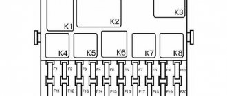
The Panasonic air conditioning system mounting block looks like this, as shown in the photo below.
They are responsible for protecting and switching the following circuits:
- K1 - turning on the air conditioner radiator cooling fan at maximum speed.
- K2 - right cooling fan.
- K3 - sequential activation of fans at low speed.
- K4 - right cooling fan.
- K5 - heater fan.
- K6 - compressor.
- F1 (30A) - left fan at low speed.
- F2 (30A) - right fan.
- F3 (40A) - heater fan.
- F4 (15A) - compressor.
If the fans malfunction, first check the fuses and relays in the mounting block of the air conditioning system.
The installation block of the Halla air conditioning system on the Priora has minor differences. The photo below shows what it looks like with the elements labeled.
They have the following purpose:
- F1 (30A) - fuse for the right fan power supply circuit.
- F2 (30A) - left fan power supply fuse.
- F3 (40A) - heater fan power fuse.
- F4 (15A) - compressor power fuse.
- K1 - right fan relay.
- K2 - additional relay for turning on the right and left fans.
- K3 - left fan relay.
- K4 - heater fan relay.
- K5 - compressor relay.
Knowing the location of the corresponding fuses and relays, it will not be difficult to check the electrical circuit and detect malfunctions.