Renault Logan
belongs to the class of budget cars. In Europe it is also known as Dacia Logan. It was produced in station wagon and sedan bodies.
Renault Logan 1 of the first generation was produced in 2005, 2006, 2007, 2008, 2009, 2010, 2011, 2012 and 2013 with 1.4 and 1.6 gasoline engines and 1.5 liter diesel engines. The 2nd generation was produced in 2014, 2015, 2016, 2022, 2022, 2022 and to the present.
We will show you where the blocks with fuses and relays are located for Renault Logan 1st and 2nd generations, their photographs and diagrams describing the purpose of the elements, and we will also show you how to replace the cigarette lighter fuse.
Please note that the number of elements, as well as their location in the blocks, depends on the configuration and year of manufacture of the car and may differ from the information provided.
Renault Logan 1
Fuses and relays under the hood
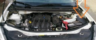
In the engine compartment of the 1st generation model, two different options for the arrangement of elements are possible. In both of them, the main units are on the left side, next to the battery.
Option 1
- Photo - diagram
- Description
| 597A - F1 | (60A) Security alarm, exterior lighting switch, daytime running light relay (block 1034) |
| 597A - F2 | (60A) Exterior light switch, interior fuse box |
| 597V - F1 | (30A) Relay board power supply |
| 597V - F2 | (25A) Injection relay power supply circuit |
| 597V - F3 | (5A) Injection relay power supply circuit, injection ECU |
| 597C - F1 | (50A) ABS ECU |
| 597C - F2 | (25A) ABS ECU |
| 597D - F1 | (40A) High speed fan relay (relay 236), relay board |
| 299 — 231 | (20A) Fog lights |
| 299 — 753 | (20A) Headlight washer pump |
| 784 — 474 | (20A) Air conditioning compressor activation relay |
| 784 — 700 | (20A) Low speed fan relay |
| 1034 — 288 | (20A) Daytime running light relay |
| 1034 — 289 | (20A) Same |
| 1034 — 290 | (20A) Same |
| 1047 — 236 | (20A) Fuel pump relay |
| 1047 — 238 | (20A) Injection blocking relay |
| 233 | (40 A) Heater Fan Relay |
| 236 | (40 A) High speed fan relay |
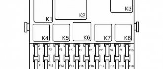
Option 2
Scheme
Designation
| F01 (60A) | Circuits: power supply to the ignition switch and all consumers powered from the lock; outdoor lighting switch |
| F02 (30A) | Cooling fan relay K3 power circuit (on a vehicle without air conditioning) |
| F03 (25A) | Power circuits: relay K5 of the fuel pump and ignition coil; main relay K6 engine management system |
| F04 (5A) | Circuits: constant power supply to the engine control system ECU; windings of the main relay K6 of the engine control system |
| F05 (15A) | Not used |
| F06 (60A) | Interior fuse box power supply circuit |
| F07 (40A) | Power circuits: air conditioning relay K4; relay K3 low speed cooling fan (on a car with air conditioning); relay K2 high speed cooling fan (on a car with air conditioning) |
| F08 (50A) and F09 (25A) | ABS computer circuits |
- K1 - heater fan relay, heater fan motor. See information about F36.
- K2 - high-speed cooling fan relay (for cars with air conditioning), radiator cooling fan electric motor.
- Short circuit - low speed cooling fan relay (for cars with air conditioning) or radiator cooling fan relay (for cars without air conditioning), cooling fan electric motor (for cars with air conditioning - through a resistor).
- K4 - air conditioning relay, compressor electromagnetic clutch. See information about F36.
- K5 - fuel pump and ignition coil relay.
- K6 - main relay of the engine control system, oxygen concentration sensor, speed sensor, fuel injectors, solenoid adsorber purge valve, relay windings K2, KZ, K4.
- K7 - headlight washer pump relay.
- K8 - fog lamp relay. See information about F31.
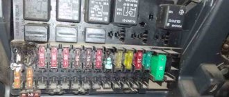
Fuses in the cabin
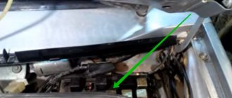
The main unit is located at the left end of the instrument panel under a plastic cover, on the back of which there will be an up-to-date description of the fuses.
Scheme
Decoding
| F01 (20A) | Windshield wiper; Rear window heating relay coil |
| F02 (5A) | Power supply for instrument cluster; relay windings K5 of the fuel pump and ignition coil; power supply to the engine control system ECU from the ignition switch |
| F03 (20A) | Brake lamps; reversing lamps; windshield washer |
| F04 (10A) | Circuits: airbag control unit; direction indicator lamps; engine management system diagnostic connector; immobilizer coils |
| F09 (10A) | Circuits: headlight bulbs of the left block headlight (low beam); signaling device for turning on low beam headlights in the instrument cluster; headlight washer pump |
| F10 (10A) | Headlight bulbs for the right headlight (low beam) |
| F11 (10A) | Left headlight headlight bulbs (high beam); high beam headlight indicator in the instrument cluster |
| F12 (10A) | Headlight bulbs for the right headlight (high beam) |
| F13 (30A) and F14 (30A) | Electric window circuits for rear and front doors, respectively |
| F15 (10A) | ABS ECU |
| F17 (15A) | Signal |
| F18 (10A) | Left side headlight lamps; side light bulbs of the left rear light; license plate lamps; illumination of the instrument cluster and controls on the instrument panel, console and floor tunnel lining; switch box buzzer |
| F19 (7.5A) | Side light bulbs for the right headlight; side light bulbs for the right rear light; glove compartment lamps |
| F20 (7.5A) | Lamps and indicator for turning on the rear fog lamp |
| F21 (5A) | Circuit of heating elements of external rear-view mirrors |
| F28 (15A) | Interior lamps; trunk lamps; constant power supply to the head unit for sound reproduction |
| F29 (15A) | Circuits: hazard warning switch; direction indicator switch; intermittent operation of the windshield wiper; central locking control; engine management system diagnostic connector |
| F30 (20A) | Central locking power circuit |
| F31 (15A) | K8 relay coil circuit for fog lights |
| F32 (30A) | Rear window defroster relay power circuit |
| F36 (30A) | Heater fan relay K1 power circuit |
| F37 (5A) | Electric drive circuits for exterior rear view mirrors |
| F38 (10A) | Cigarette lighter; power supply to the head unit for sound reproduction from the ignition switch |
| F39 (30A) | Heater fan relay K1 coil circuit |
Fuse number 38 for 10A is responsible for the cigarette lighter.
Watch the video for an example of accessing the unit, as well as replacing the cigarette lighter fuse.
Renault Logan 2
Relays and fuses under the hood
The mounting block is located on the left side, next to the battery and is covered with a plastic cover.
Scheme
Designation
- Battery terminal
- A/C compressor diode
| Ef1 | 40A Right windshield heating element |
| Ef2 | 40A Left windshield heating element |
| Ef3 | 50A ABS/ESP |
| Ef4 | 60A Immobilizer, power supply circuit for passenger compartment fuses F28-F31 |
| Ef5 | 60A Power supply for passenger compartment fuse circuits F11, F23 - F27, F34 and F39 |
| Ef6 | 30A ABS/ESP |
| Ef7 | 30A Heated rear window and mirrors |
| Ef8 | 15A Front fog lights |
| Ef9 | 15A Heated seats |
| Ef10 | 15A Air conditioner clutch (equipment with air conditioner) / 25A First speed of the electric fan (equipment without air conditioner) |
| Ef11 | 25A Fuse for Engine Control Relay |
| Ef12 | 40A Electric cooling fan |
| Ef13 | 15A Engine control system |
| Er1 | 35A Left heated glass relay |
| Er2 | 35A Relay for right heated glass |
| Er3 | 20A Fuel pump relay |
| Er4 | 20A Relay for air conditioning compressor or first speed electric fan (depending on configuration) |
| Er5 | 35A Engine Control Relay |
Fuses and relays in the cabin
Just like the 1st generation, this block is installed at the end on the left.
Scheme
Purpose
| F1 | 30A electric front windows |
| F2 | 10A high beam left headlight |
| F3 | 10A high beam right headlight |
| F4 | 10A low beam left headlight |
| F5 | 10A high beam right headlight |
| F6 | 5A rear lights, license plate light, backlight |
| F7 | 5A front dimensions |
| F8 | 30A electric rear windows |
| F9 | 7.5A rear fog light |
| F10 | 15A horn |
| F11 | 20A central locking |
| F12 | 3A ABS/ESP |
| F13 | 10A interior lighting, air conditioning |
| F14 | 5A steering angle sensor |
| F15 | 15A windshield washer, parking radar, reversing light |
| F16 | 5A audio system, heated glass, speed limiter |
| F17 | 7.5A DRL |
| F18 | 7.5A brake light |
| F19 | 5A control system |
| F20 | 5A airbag |
| F21 | reserve |
| F22 | reserve |
| F23 | reserve |
| F24 | 15A turn signal |
| F25 | 10A anti-theft system |
| F26 | 15A electrical control unit |
| F27 | 20A steering column switches (low beam input) |
| F28 | reserve |
| F29 | 25A steering column switches (high beam input) |
| F30 | reserve |
| F31 | 10A instrument panel |
| F32 | 7.5A audio system |
| F33 | 15A cigarette lighter |
| F34 | 15A diagnostic connector |
| F35 | 5A heated exterior mirrors |
| F36 | 5A mirror drive |
| F37 | 30A starter |
| F38 | 30A windshield wiper |
| F39 | 40A air conditioner |
| R1 | 35A A/C relay |
| R2 | 35A rear defroster relay |
Block under the hood
In the engine compartment, the block is located on the left side, under the protective cover.
Purpose
- 40 Controlled suspension
- 60 ABS
- 70 Engine preheating
- 60 Ignition switch, direction indicators, telephone, door lock, courtesy light, clock
- 60 Heating, current electric seats, electric windows
- 60 Anti-theft switch, parking lights, hazard warning lights
- 60 Ignition switch, windshield wipers, windshield washers, cigarette lighter
- 40 Left radiator fan
- 40 Right radiator fan
- 40 Turn signals, headlight washers
Renault Logan starter relay where it is located - we explain the essence
4903
A common problem that sooner or later faces the owner of any car is starter failure. In this case, the car engine does not start or even turn over. If your Renault Logan does not want to turn the starter, then it’s time to repair it. This is exactly the topic that will be discussed in our article.
Diagnosis and causes
Turn the key and try to start the engine, if the engine does not start and the starter does not turn, and instead of the usual sound you only hear it clicking, so you can say that the rotor brushes have come to an “end”.
To give an explanation of why the relay clicks and the engine does not start, you need to understand the scheme of its operation. At the moment when you turn the key to the engine start position, a special block called a retractor makes contact on the rotor shaft brushes, thereby the starter spins the engine flywheel.
When this mechanism or relay does not work, it urgently needs to be removed and repaired, otherwise extremely serious consequences can occur, including fire.
This is the principle behind the work of the starter and its relay. When the brushes are worn out, the relay tries to operate and make contact on the shaft; if it clicks, the brushes are worn out, and it’s time to change them.
To the question of where the starter and its relay are located, we will answer unequivocally - near the rear flywheel of the engine. This arrangement is typical for all engines, including Renault Logan 1.4.
If the starting device idles and the engine does not start, then you need to change the bendix, and possibly the fork. This work can be done without any problems with your own hands, but first remove the on-board voltage.
When the relay clicks, you need to understand that the problem is definitely not with it, it works.
Repairing this unit, as well as replacing the bendix, can easily be done with your own hands, but to do this you will need to remove the entire unit.
Renault Logan fuses and relays, electrical diagrams
Renault Logan is considered an inexpensive, affordable and reliable car. It’s not for nothing that many people use these cars to work as taxis. At a relatively low cost, this model is quite reliable for Russian roads.
But in any car, especially after long trips and a certain number of kilometers, certain problems begin to appear related to electrical appliances, contacts, and wiring.
This is especially noticeable on older cars that have served more than one owner.
To quickly find and fix electrical faults in Logan, you need to know where the Renault Logan fuses and relays are located, how the circuits and power supply circuits of the devices are made. Mounting blocks and ways to solve electrical problems will be discussed in this article.
Renault Logan 1
Fuses and relays under the hood
In the engine compartment of the 1st generation model, two different options for the arrangement of elements are possible. In both of them, the main units are on the left side, next to the battery.
Option 1
- Photo - diagram
- Description
| 597A - F1 | (60A) Security alarm, exterior lighting switch, daytime running light relay (block 1034) |
| 597A - F2 | (60A) Exterior light switch, interior fuse box |
| 597V - F1 | (30A) Relay board power supply |
| 597V - F2 | (25A) Injection relay power supply circuit |
| 597V - F3 | (5A) Injection relay power supply circuit, injection ECU |
| 597C - F1 | (50A) ABS ECU |
| 597C - F2 | (25A) ABS ECU |
| 597D - F1 | (40A) High speed fan relay (relay 236), relay board |
| 299 — 231 | (20A) Fog lights |
| 299 — 753 | (20A) Headlight washer pump |
| 784 — 474 | (20A) Air conditioning compressor activation relay |
| 784 — 700 | (20A) Low speed fan relay |
| 1034 — 288 | (20A) Daytime running light relay |
| 1034 — 289 | (20A) Same |
| 1034 — 290 | (20A) Same |
| 1047 — 236 | (20A) Fuel pump relay |
| 1047 — 238 | (20A) Injection blocking relay |
| 233 | (40 A) Heater Fan Relay |
| 236 | (40 A) High speed fan relay |
Option 2
Scheme
Designation
| F01 (60A) | Circuits: power supply to the ignition switch and all consumers powered from the lock; outdoor lighting switch |
| F02 (30A) | Cooling fan relay K3 power circuit (on a vehicle without air conditioning) |
| F03 (25A) | Power circuits: relay K5 of the fuel pump and ignition coil; main relay K6 engine management system |
| F04 (5A) | Circuits: constant power supply to the engine control system ECU; windings of the main relay K6 of the engine control system |
| F05 (15A) | Not used |
| F06 (60A) | Interior fuse box power supply circuit |
| F07 (40A) | Power circuits: air conditioning relay K4; relay K3 low speed cooling fan (on a car with air conditioning); relay K2 high speed cooling fan (on a car with air conditioning) |
| F08 (50A) and F09 (25A) | ABS computer circuits |
- K1 - heater fan relay, heater fan motor. See information about F36.
- K2 - high-speed cooling fan relay (for cars with air conditioning), radiator cooling fan electric motor.
- Short circuit - low speed cooling fan relay (for cars with air conditioning) or radiator cooling fan relay (for cars without air conditioning), cooling fan electric motor (for cars with air conditioning - through a resistor).
- K4 - air conditioning relay, compressor electromagnetic clutch. See information about F36.
- K5 - fuel pump and ignition coil relay.
- K6 - main relay of the engine control system, oxygen concentration sensor, speed sensor, fuel injectors, solenoid adsorber purge valve, relay windings K2, KZ, K4.
- K7 - headlight washer pump relay.
- K8 - fog lamp relay. See information about F31.
Fuses in the cabin
The main unit is located at the left end of the instrument panel under a plastic cover, on the back of which there will be an up-to-date description of the fuses.
Scheme
Decoding
| F01 (20A) | Windshield wiper; Rear window heating relay coil |
| F02 (5A) | Power supply for instrument cluster; relay windings K5 of the fuel pump and ignition coil; power supply to the engine control system ECU from the ignition switch |
| F03 (20A) | Brake lamps; reversing lamps; windshield washer |
| F04 (10A) | Circuits: airbag control unit; direction indicator lamps; engine management system diagnostic connector; immobilizer coils |
| F09 (10A) | Circuits: headlight bulbs of the left block headlight (low beam); signaling device for turning on low beam headlights in the instrument cluster; headlight washer pump |
| F10 (10A) | Headlight bulbs for the right headlight (low beam) |
| F11 (10A) | Left headlight headlight bulbs (high beam); high beam headlight indicator in the instrument cluster |
| F12 (10A) | Headlight bulbs for the right headlight (high beam) |
| F13 (30A) and F14 (30A) | Electric window circuits for rear and front doors, respectively |
| F15 (10A) | ABS ECU |
| F17 (15A) | Signal |
| F18 (10A) | Left side headlight lamps; side light bulbs of the left rear light; license plate lamps; illumination of the instrument cluster and controls on the instrument panel, console and floor tunnel lining; switch box buzzer |
| F19 (7.5A) | Side light bulbs for the right headlight; side light bulbs for the right rear light; glove compartment lamps |
| F20 (7.5A) | Lamps and indicator for turning on the rear fog lamp |
| F21 (5A) | Circuit of heating elements of external rear-view mirrors |
| F28 (15A) | Interior lamps; trunk lamps; constant power supply to the head unit for sound reproduction |
| F29 (15A) | Circuits: hazard warning switch; direction indicator switch; intermittent operation of the windshield wiper; central locking control; engine management system diagnostic connector |
| F30 (20A) | Central locking power circuit |
| F31 (15A) | K8 relay coil circuit for fog lights |
| F32 (30A) | Rear window defroster relay power circuit |
| F36 (30A) | Heater fan relay K1 power circuit |
| F37 (5A) | Electric drive circuits for exterior rear view mirrors |
| F38 (10A) | Cigarette lighter; power supply to the head unit for sound reproduction from the ignition switch |
| F39 (30A) | Heater fan relay K1 coil circuit |
Causes of cigarette lighter failure
The device may stop working due to various factors. The main reasons for a malfunction of the Duster cigarette lighter are improper operation of the device or great age, or a blown fuse. Common breakdowns.
- A loose nest. Frequently connecting foreign electrical devices with a non-standard plug to the connector can bend the fixing antennae, causing the contact to disappear. Repairing the Duster cigarette lighter in this case is simple - you need to remove it from the socket and then bend the clamps inside the socket. To avoid short circuit, you must remove the fuse before this procedure.
- Oxidized contacts or plaque. Age-related disease. It may also appear after liquid gets on the legs. Because of this, the integrity of the circuit is compromised, and in extreme situations there is a risk of the fuse tripping and a short circuit. Repairing the cigarette lighter is simple - just rub the contact areas with sandpaper or a file, removing traces of foreign substances.
- Burnt fuse. The maximum current strength of this segment of the electrical circuit is 15 amperes. The maximum permissible power of connected devices is 180 Watt (p=I*A, 180 Watt = 12 volts*15 amperes). Due to a short circuit or exceeding the permissible value, this parameter may go out of range. To protect the wiring insulation from melting, the fuse on the Duster fails. The repair consists of getting to the mounting block. Next, replace the blown fuse.
- "Shorty." If the new fuse blows again, then it is obvious that there is a short circuit in the network. Turn off the ignition and then measure the battery voltage. Turn on the ignition and take measurements again. A difference of more than 0.5 volts is unacceptable - this is evidence of a short circuit and a tripped fuse. You should arm yourself with a multitester and test all the wires going to the device.
- Fallen cables. Due to age or intensive use, the wires on the Duster cigarette lighter may fray or fall off at the soldering points. The fuse trips. You should test all cords for resistance, and also inspect them to see if there are any creases, exposed wiring, or broken areas. Broken cords must be replaced with new ones, and missing soldering points must be soldered using a soldering iron and tin.
- Burnt-out filament. After prolonged exposure to temperature, the spiral inside the rod may burn out, causing the device to stop functioning. It will be necessary to remove the Renault Duster cigarette lighter, and then replace it with a new spare part.
- Broken backlight lamp. The light bulb that guarantees the operation of the filter may burn out due to age or constant shaking. To replace it, you will need to remove the cigarette lighter, dismantle the filter and change the lamp.
Thus, it can be seen that all electrical circuits pass through the fuse box under the hood of the Renault Duster, and only after that, through the block in the car’s interior. If a fuse blows, it must be replaced with the same one so that the markings match.
Renault Logan fuse diagram
The electrical circuit according to which the Renault Logan provides power to the cigarette lighter unit is very primitive. The standard source sends voltage to the fuse (10A), which is located inside the mounting module.
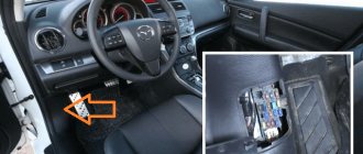
This fuse box is located in the cabin, or more precisely, above the Renault Logan hood release handle. Wires connect two objects: the mounting block itself and the corresponding socket on the console.
In this article we will tell you where a very important element is located - the cigarette lighter fuse, as well as other fuses and relays, as well as a fuse diagram for a Renault Logan car.
If a malfunction occurs, you should first make sure that the corresponding fuses are intact. Its markings are red and have the symbols “F38”. It is important to remember that there is no cigarette lighter symbol on the surface of the mounting block cover. The cigarette lighter fuse is powered by the audio system.
This forces you to navigate precisely by its designation. Therefore, you can easily find where the very important element, the cigarette lighter fuse, is located, since due to the numerous gadgets connected to it (laptops, smartphones, etc.), these fuses fail more often than others, not only on Renault Logan.
Among the most common causes of block burnout is the fact that a large number of simultaneously functioning energy consumers are connected to the Renault Logan on-board network. If any of the devices consumes a current whose value exceeds 10A, then subsequent burnout is guaranteed.
Here among the leaders is the electric pump. To prevent damage to the unit, the procedure for inflating the wheels should be performed with the audio system turned off, since the radio and the pump are powered through the same circuit.
Before connecting the hose to the nipple, pause, allowing the pump to run idle for a short time.
Another important cause of failure may be the incompatibility of the size of the pantograph plug with the power socket. Loose contact causes increased heating of the terminals. Upon reaching a specific temperature value, the terminals begin to melt and cause a short circuit. In such a situation, replacing a single fuse cannot be done. The entire block has to be replaced.
Location of the “F38” in the mounting block of the 1.4-liter Renault Logan:
Preventive actions
If you don't want to constantly stock up on tons of fuse sets, you should implement a strategy to counteract their frequent failures.
- The first and most common method is to use fuses on an analogue with a higher power. Experts recommend using devices with a power of 15A. The likelihood of burnout is minimized, and damage to the on-board network does not occur.
- The second measure will be the correct selection of the device. The packaging containers of the most diverse products indicate their power consumption. It’s great if they have their own element. To prevent burnout, carefully read the characteristics of the device you intend to purchase. This is a simpler action compared to “uprooting” the fuse from its socket.
- Thirdly, the plug must be connected correctly. Due to its inconsistency with the design features of the nest, the above problems arise.
To ensure correct connection, the location of the contacts must be horizontal, but not vertical (that is, on the sides, but not at the top and bottom). This action will prevent melting of the terminals in the Renault Logan car.
If a malfunction does occur and the fuses become unusable, then the only solution is replacement. The procedure is quite simple. In order to remove the fuses from the mounting socket, it will be enough to pry them with a flat-profile screwdriver.
About security measures
The fuse box is designed to prevent a fire hazard that occurs due to a short circuit in the electrical network of a Renault Logan car. Even the presence of a block does not allow you to be completely insured against trouble.
- Renault Duster rear view camera
- Comparison of Renault Duster and Kia Sportage 2
- Renault Sandero cabin filter replacement
Removal and replacement process
To replace failed parts, you will need plastic tweezers, included with the car, and a screwdriver with a narrow flat blade.
Under the hood
The procedure is as follows:
- Turn off the ignition and remove the key from the lock,
- Take puller tweezers.
- Open the driver's door.
- Remove the cover from the interior unit.
- Open the hood.
- Remove the mounting block cover by unlatching the latches on the desired side (for machines assembled before 05/17/2005) or by sliding the latches (for machines assembled after 05/17/2005).
- Using tweezers or your hand, pull out the failed relay or fuse. If this cannot be done, you can use a screwdriver by inserting its tip into the slot on the fuse and pulling up.
- Eliminate the cause of the fuse-link burnout or relay failure.
- Install a new fuse or relay.
- Reinstall the removed parts in their original locations.
Renault Logan fuse diagram
The fuses and relays of the 2nd generation Renault Logan car perform one of the main tasks - instead of burning out the electrical circuit, they burn out themselves.
Only the relays also switch high currents in the protective casing of the switchboard.
These elements are located in two places in the second generation Renault Logan - in the power unit compartment and in the vehicle interior.
Fuse selection, original and analogue
Fuse table for Renault Logan 2nd generation, article number and approximate cost:
| vendor code | Name | Color | Cost, rub. |
| 243809584R | Block body | 1 900 | |
| 8200248099 | 25a | Grey | 350 |
| 7700410540 | maxi 40a | Orange | 350 |
| 7700410541 | maxi 50a | Red | 270 |
| 7700410542 | maxi 60a | Light blue | 180 |
| 7700410574 | mikro 10a | Red | 90 |
| 7700410576 | mikro 20a | Yellow | 100 |
| 7700410577 | mikro 25a | White | |
| 7700410578 | mikro 30a | White, beige, green | |
| 7700410572 | mikro 5a | Light brown | |
| 7700410550 | mini 15a | Light blue | |
| 7700410553 | mini 30a | Light blue | |
| 7700410548 | mini 7.5a | Brown | |
| 8200253921 | Relay 12v 40a | 2 700 | |
| 8200263342 | Relay 20a (p/t headlights) | 2 300 | |
| 7700844253 | Fan relay, 12v40a | Yellow | 400 |
| 7700414484 | Starter relay, 20a | Black | 1 000 |
Important information: when choosing fuses, preference should be given to original spare parts. However, to save money, similar options are also suitable, but you should find out in advance about the quality and service life of the elements.
In a second-generation Renault Logan car, fuses and relays are located in two places, namely: in the engine compartment and in the passenger compartment.
The mounting block in the power unit compartment is located on the left side under the cover. To gain access to the elements, remove the cover.
- Location diagram of the fuse box in the engine compartment:
- Here the fuses are responsible for the following.
- Ef 1. Right windshield heated component.
- Ef 2. Left windshield heating component.
- Ef 3. Anti-lock braking system control unit (50 A).
- Ef 4. Power supply circuits for fuses F28 – F31 in the passenger compartment.
- Ef 5. Power supply circuits for fuses F11, F23 – F27, F34, F39 in the passenger compartment.
- Ef 6. Anti-lock braking system control unit (30 A).
- Ef 7. Heated rear window and exterior mirrors.
- Ef 8. Front fog lights.
- Ef 9. Heated front seats.
- Ef 10. If there is an air conditioner, this is the compressor clutch.
- Ef 11. ECM main relay. Fuel pump relay, fuel pump, fuel quantity analysis device, ignition coil, air conditioning compressor relay winding, electric fan first speed relay winding, electronic engine control unit.
- Ef 12. Power unit cooling mechanism block.
- Ef 13. Power unit control mechanism.
Diagram of the second fuse box of the second generation Renault Logan:
The purpose of the elements is as follows.
- F 1. Electric front window lifts.
- F 2 and F 3. High beam of the left and right headlights, respectively.
- F 4 and F 5. Low beam of the left and right headlights, respectively.
- F 6 and F 7. Dimensions on the right and left, respectively.
- F 8. Electric rear window lifts.
- F 9. Rear fog light.
- F 10. Sound signal.
- F 11. Central locking.
- F 12. ABS system, directional stability and brake signals.
- F 13. Climate control control unit, as well as interior and luggage compartment lighting.
- F 14. Steering angle device.
- F 15. Windshield washer and wiper, reversing light.
- F 16. Audio system, seat belt warning, heated rear window and windshield relay.
- F 17. Daytime running lamps.
- F 18. Brake alert.
- F 19. Control system.
- F 20. Airbags.
- F 21, F 22, F 23, F 28 and F 30. Reserve.
- F 24. Turn signals.
- F 25. Anti-theft system and electrical equipment control sensor.
- F 26. Dimensions, electric external rear view mirrors, turn signals, central locking and hazard warning switch.
- F 27 and F 29. Switches under the steering wheel.
- F 31. Instrument panel.
- F 32. Audio system.
- F 33. Cigarette lighter.
- F 34. Connectors for radio.
- F 35. Heated exterior mirrors.
- F 36. Electric drive of external mirrors.
- F 37. Starter.
- F 38. Windshield wiper.
- F 39. Climate control.
Replacing the fuse box
This procedure is required when the fuses begin to blow. This means that their service life has expired, or the problem is related to contamination, moisture and other factors that lead to rapid wear of the elements of the 2nd generation Renault Logan car.
To replace, the first step is to turn off the powertrain and remove both terminals from the battery. Then remove the fuse box cover. Unscrew the bolts and remove the spare part.
After dismantling, install a new unit.
Important information: if you are not confident in your abilities, it is recommended to contact a service center to repair the damage. Experienced mechanics will carry out the procedure quickly and at an affordable cost.
Source: https://loganlogan.ru/renault-logan-repair/predohranitelej-reno-logan-shema-zamena-i-blok-predohranitelej.html
Cigarette lighter repair
A malfunctioning device must be restored. When removing the cigarette lighter, perform the following steps:
- Inspect areas that are frequently damaged. They start by checking the contacts for the presence of an oxide film. If the driver finds traces of rust, it is recommended to treat the elements with sandpaper or an anti-corrosion agent. The contacts are bent to ensure firm fixation in the socket.
- Inspect the fuse and wiring, which is located on the back of the unit. To check, use a multimeter, which is switched to resistance determination mode. All wires going to the block are ringing. If there is no contact, look for the break point. The conductors are soldered with a soldering iron.
- They assemble the device, evaluate its performance by connecting different devices.
Replacement and connection
Before installing a new part, you need to remove the old one using the above method. After this, place the device in the seat and connect the wire block. If necessary, you can change the plastic holders that secure the cigarette lighter in the center console. Install the block, close the latches of the lighting fixture. Solder the black wire to the car cigarette lighter cylinder. The reverse end of the cable is brought out to the body. The red wire is connected to the heating element. The yellow cable is connected to the backlight. Both wires lead to the battery.
vote
Article rating
Fuel pump diagnostics
In order not to make a mistake when buying a new part, you should be sure that it is the fuel pump that is not working. To do this, you will have to carry out a number of diagnostic operations. So let's get started:
- The first diagnostic operation will be to simply turn on the ignition switch. If you turn the key to position No. 2, the fuel pump will create a certain sound that will be heard. If he didn’t appear, then that’s definitely the reason.
- The next step is to examine fuses and relays.
Examine the fuse (F02 (5 A)), which is responsible for the operation of the fuel pump, and determine its functionality. Change if necessary. Location of fuses in the main unit - Now you should diagnose the relay. To do this, you need to turn the ignition key several times, if it clicks, then everything is fine. It will not be possible to check the relay using diagnostic programs that work through the connector.
- If all of the above elements are intact, then the fuel pump is “dead” and must be replaced.
Prevention options
In order not to constantly purchase a large number of fuses, you need to apply preventive measures.
- The most common way to avoid frequent failure of fuses is to replace them with a more powerful element. Experts recommend installing the device at at least 15 amperes. In this case, the likelihood of problems occurring and fuses blowing is reduced significantly.
- Secondly, you need to carefully select devices, since the electrical power is indicated on the packaging of DVRs, car radios and other products used in cars. To avoid blowing fuses, you need to carefully read their technical characteristics and only then connect them to the car’s electrical network.
- The third condition is that it is recommended to connect the plug correctly. Since due to a mismatch between the standards of the plug and socket of the device, certain problems may arise. The plug is connected correctly if the contacts are in a horizontal position, i.e. on the sides (not below and not above!). This arrangement will avoid burnout and melting of the terminals.
But if a problem does arise and the element burns out, then it will have to be replaced with a new one. This procedure is extremely simple; in Renault Logan you can get it out by prying it off with a thin flat-head screwdriver.
Brake light faults
View of the additional brake light from inside the car
If you decide to start or continue driving a car when the brake lights are faulty, this means exposing not only yourself, but also all other road users to danger. Therefore, lamps should be periodically monitored and maintained.
Among the problems, the most common cases are:
- During braking, the brake light does not work on one side.
- When braking, the brake lights on both sides do not work.
- Additional signal light does not work
Diagnostic and repair methods
Since the functioning and performance of these outdoor lighting elements directly depends on the performance of the vehicle’s electrical network, it is necessary to pay close attention to its condition. If all the brake lights on your car stop working at once, the reason for this is most often the failure of fuse F3 (for the passage of current with a force of no more than 20A) located in the Renault Logan interior fuse box
If all the brake lights on your car stop working at once, the reason for this is most often the failure of fuse F3 (for the passage of a current with a force of no more than 20A) located in the fuse box of the Renault Logan interior.
The location of the fuse we need is marked with a red marker.
This element is part of the direct power supply circuit to the brake lights. You can check the serviceability of the circuit using a known good fuse or using a tester (multimeter). If such manipulations do not bring the desired result, and the lights still do not work, then the search for the fault must be continued. The next step in the repair will be to check the wiring for evidence of breakage or chafing of the wire in the circuit.
Next, an element that can also cause a malfunction is the brake lamp switch on Renault Logan, which is installed on the bracket with the pedals. For more effective diagnostics, it is best to remove it from its seat. This work is carried out in the following order:
- Since the circuit of this sensor is constantly energized, you should disconnect the negative terminal from the battery.
- Next, remove the connector with wires.
- In order to pull it out from its place of fixation, you need to turn the sensor body 90 degrees and slowly pull it towards you until it is completely dismantled.
To check the sensor, you can use a tester and measure its resistance, or connect a known-good sensor. Checking the device with a tester is very easy; we connect the tester wires to the sensor connectors, and use our hands to operate on the protruding rod. A working device will thus show its functionality, but a broken one must be replaced.
The next step is to check that the mains voltage is reaching the working sensor. We connect the battery back to the network and use the equipment to check the voltage in the sensor terminals. If the result is positive, we put everything back together in reverse order and proceed to direct diagnosis and replacement of the brake light bulbs.
Option 2
Photo
Scheme
Circuit breakers
Relay
Purpose
| F1 | (10A) Front left/rear left side lamps |
| F2 | (10A) Front right marker/rear right marker lamps |
| F3 | (7.5A) Door mirror heater |
| F6 | (25A) Power seats |
| F7 | (15A) Air conditioning system, central locking, immobilizer |
| F8 | (15A) Hazard warning |
| F9 | (25A) Rear window wiper |
| F10 | (3A) Motor control |
| F11 | (15A) Cigarette lighter |
| F12 | (25A) Windshield wiper |
| F13 | (10A) Air conditioning system, reversing lights |
| F14 | (20A) Seat heater |
| F15 | (25A) Windshield wiper |
| F16 | (15A) Left headlight - high beam |
| F17 | (15A) Right headlight - high beam |
| F18 | (7.5A) Reversing lights |
| F19 | (10A) Hatch |
| F20 | (10A) Bi-fuel fuel supply system |
| F21 | (15A) Fog lights |
| F22 | (10A) Rear fog lights |
| F23 | Jumper - "ACC" position |
| F24 | (15A) Engine management system - Diesel |
| F25 | (20A) Horn |
| F26 | (5A) Anti-theft system, audio system |
| F27 | (10A) Audio system, telephone |
| F28 | (10A) Interior lamps |
| F29 | (20A) Audio system, switch illumination |
| F30 | (5A) Suspension control system |
| F31 | (3A) heater/air conditioner |
| F32 | (15A) Audio system |
| F33 | heater/air conditioner |
| F34 | (5A) Instrument cluster |
| F35 | (5A) Audio CD changer |
| F36 | (5A) Automatic transmission |
| F37 | (7.5A) Anti-lock brake system (ABS) |
| F38 | (30A) Motor control |
| F39 | (15A) Airbag, anti-theft system, instrument cluster |
| F40 | (20A) Cruise Control, Hazard Lights, Brake Lights, Active Suspension System |
| F41 | (30A) Power windows |
| F42 | (30A) Power windows |
| F43 | Jumper - automatic transmission control system, main ignition circuit relay |
| F61 | (5A) Engine management system (Bi-fuel) |
- Air conditioner relay
- Rear power window relay
- Rear window defroster relay
- Rear fog lamp relay
- Interior lamp relay - rear
- Anti-theft relay
- Front fog lamp relay
- Relay 1 main ignition circuits
- Relay 2 main ignition circuits
- Windshield wiper intermittent relay
- Diagnostic connector (DLC)
About security measures
The fuse box is designed to prevent a fire hazard that occurs due to a short circuit in the electrical network of a Renault Logan car. Even the presence of a block does not allow you to be completely insured against trouble.
Among the most common factors that cause a fire is the failure of the cigarette lighter due to negligence when handling it. To prevent such an emergency you will need:
- carefully familiarize yourself with the features of the instructions for the connected devices (the most dangerous are on-board voltage converters to 220V);
- purchase only high-quality fuses and relays;
- choose the right plug, which will ensure a tight fit inside the power socket and prevent spontaneous falling out under conditions of strong shaking;
- the cable supplying the device should not be subject to tension, which will allow the plug to be held in the socket;
- It is strongly recommended not to leave devices turned on unattended in cases where the cigarette lighter socket in the Renault Logan is not de-energized when the ignition is turned off.
About the features of the system design
The design of the fuel supply system to the Renault Logan engine implies the presence of several components through which the fuel-air mixture under pressure enters the combustion chambers of the cylinders. The main elements of this system are:
- gas tank;
- main fuel line;
- fuel rail;
- return line;
- nozzles;
- pressure regulator;
- fuel gasoline pump;
- level sensor and filter.
Sometimes the fuel pump needs to be replaced. The functioning of the system under consideration is subordinated to an on-board computer, which, in real time, based on signals from various sensors, adjusts the operation in order to ensure that the mixture is supplied to the combustion chambers with an optimal ratio of fuel and air.
Key-dop
- When the ignition key is turned to the 2nd position, the fuel pump relay is turned on, which operates for several seconds, providing the required pressure in the fuel rail. The engine can then be started. This is the normal operating mode of the system.
- When the Renault Logan engine starts, the relay is activated again, ensuring that the pump operates continuously throughout the entire engine operation. Thanks to this, fuel is supplied to the ramp continuously through the fuel pump. In it, the regulator ensures that constant fuel pressure is maintained, eliminating the formation of excess (it returns to the tank via the return line).
- If interruptions occur in the operation of the motor, the first diagnostic measure will be to check the integrity of the pump fuse and relay. And if a breakdown is detected, the fuel pump needs to be replaced.