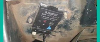
All drivers are required to signal maneuvers on the road by turning on the turn signal. This flashing light is found in every car. Its operating mode is created by a switching relay, the circuit of which supplies current to the lamps and ensures their blinking. At the same time, a clicking sound is heard, reminding you that the turn signal is on. All these actions are ensured by a special turn signal relay circuit.
Among the various designs, the most popular are electromagnetic-thermal and electronic relays. The latest devices are considered more modern and are installed on all subsequent car models.
How does an electromagnetic-thermal relay work?
These devices are no longer used in modern cars. However, they are still widely used in older models.
The design of an electromagnetic thermal relay is quite simple; it uses a circuit for connecting turn signals through an electromagnetic type relay. It is made in the form of a cylindrical core, and thin copper wire is used as winding. At the top of the core there are two groups of contacts, with metal armor installed on each side. The first group of contacts closes the circuit where there is a control light located on the instrument panel. With the help of other contacts, the circuit with the lights in the turn signals is closed. They are the ones who provide the flashing mode.
A thin nichrome rope is attached to the anchor of the main contact group. Move the armor away from the contact that is on the core. Therefore, the circuit will be open, which is normal. The core itself is installed on a special isolated platform, where the opposite end of the rope is also fixed. During operation, an electric current passes through the garland, since it, together with the resistor, is located in the switch. All elements of the device are enclosed in a cylindrical metal case.
The operating principle of an electromagnetic thermal relay is very simple. When the turn signal comes on, the circuit is closed. Under the influence of current, the nichrome string heats up and its length increases. The previously tensioned armature is attracted to the core, straightens and closes the contact in a short time. Because of this, crooked lamps begin to glow at full power. The current passes by the string, causing it to cool and contract again. As a result, the armature moves away from the core, which leads to the contacts opening. The lamps stop glowing, then the whole cycle resumes. The nichrome string heats up and cools down very quickly, so the lamps flash at an average frequency of 60–120 times per minute.
The blinking indicator light on the panel is also associated with the operation of the main group of contacts. Therefore, it works in sync with the headlights. Mini-sound signals in the form of characteristic clicks appear when the armature and contacts close and open, hitting each other.
A significant disadvantage of this device is the gradual stretching of the cable, which disrupts the normal operation of the relay. Therefore, these devices are now being replaced by more modern electronic relay designs.
Setting a more powerful sound signal through a Yamaha YBR 125 relay
Axline
Guest
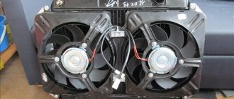
I decided to change the sound signal to a more powerful one.
There are two types of sound signals: noise hornless and tonal horn. Hornless signals are considered to be shriller and more difficult to hear, and are recommended for use on highways and in noisy environments. Horn (snail) ones are more suitable for urban conditions. Horn signals are usually installed in pairs (high and low tones). For myself, I settled on the hornless option (loud and shrill).
At an auto parts store I bought a horn from a new VAZ, large and with two terminals ((+) and (-), the old ones come with “snails” with one contact (+) and grounding to ground). The cost of this device was 120 rubles. Since the original signal was designed for a current of only 1.5A, and the new one was 5A, I decided to connect it via a relay so as not to damage the standard button. I bought a simple 4-pin 30A relay (60 rubles) from the same auto parts store. You will also need approximately 1.5 meters of wire and 4 terminals (“female”, with insulation).
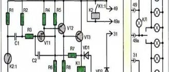
An approximate connection diagram is in the attached file (copied from www.niva.faq.msk.ru). The contact labels on the relay correspond to the figure.
In relation to YBR: Remove the wires from the standard horn. The pink one goes to the signal button (-), the brown one goes to the battery (+). In the standard circuit, the signal is constantly powered (even when the ignition is turned off), which is not a buzz at all in our humid climatic conditions.
Connect the pink wire to the contact 85
relay, brown on pin
86
.
Now, when you press the signal button, a click is heard - the relay closes contacts 30
and
87
.
We strip the brown wire and attach a short wire to it. We connect it to the contact 30
.
Now (+) is constantly supplied to pins 86
and
30
.
We take 2 long wires. We connect one to pin 87
, the second to the nearest (-). In this case, I simply stripped the pink wire and connected the second wire to it. We put these wires on the contacts of the horn. Everything is ready, you can scare the neighbors /images/smilies/wink.gif
Electronic relay: circuit and principle of operation
The design of the electronic rotation relay consists of two main parts. From a standard electromagnetic relay that performs switching to an electronic key that provides a certain frequency of operation of this device.
The nichrome cord has been replaced with an electronic key. With its help, voltage is applied and removed from the winding of the electromagnetic relay at certain intervals. The key is built on microcircuits or discrete elements. They are components of the main generator and control circuits.
The operating principle of an electronic relay is very simple. When voltage is applied to the relay, the master oscillator is activated. With its help, control pulses with different frequencies are generated, which enter the control circuit. With the help of pulses, the current flowing through the coil of the electromagnetic relay is supplied or interrupted. Such actions also cause the anchor to retract or sink. As a result, the contact groups close or open at a certain frequency, which gives the same blinking as indicator lights.
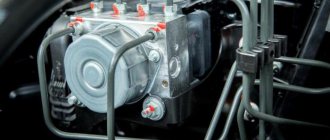
All electronic elements of the relay are mounted on a separate board. An electromagnetic relay is located above the board. Both are housed in a plastic case. The contacts are thrown out from below or to the side. There are holes and tabs for bolt connections to secure the housing.
Each electronic rotation relay has undeniable advantages over other designs. High-quality and technologically advanced devices manufactured on the basis of modern circuits and characterized by increased reliability have proven themselves. The technical characteristics of these devices remain unchanged regardless of their service life.
Where is the starter fuse located on the VAZ 2114?
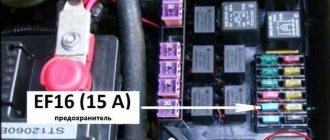
As already mentioned, there is no fuse on the VAZ 2114 starter. Perhaps the error was caused by connecting the starter through the mounting block. But this device serves as a kind of distributor, a conductor of electric current with low resistance through the busbars. The second reason that forces car owners to look for where the starter fuse is located on the VAZ 2114 is the information that the Priora has such a fuse. And it, together with the auxiliary relay, is located in the mounting block, which, unlike the VAZ Samara.
Turn signal relay pinout
During operation, the standard turn signal relay may fail and in this case it must be replaced. Incorrect operation of the device becomes obvious, especially when the indicator lamp stops lighting. The main cause of the malfunction is incomplete closing of the device.
In other cases, the relay begins to work unstably; the relay contacts close at different intervals. In some cases, the volume level of the sound accompanying the operation of the device is significantly reduced. This can create a serious problem on the road when the device turns on without the driver noticing due to accidental impacts while driving.
These shortcomings are eliminated by replacing the standard device with an electronic design. In this case, the turn relay is connected according to the standard diagram shown in the figure. Pin number 1 is positive, the second pin is used to connect to the rotation switch, the third is connected to the warning light, and the fourth is to ground.
All connections and contacts must be reliably insulated with electrical tape and cambric, which is a hollow plastic shell.
This eliminates possible short circuits with other conductors. Some disadvantages are created by the plastic housing of the electronic relay, which does not always fit into the normal position. However, home craftsmen quite easily overcome this difficulty and find the most optimal technical solution.
How to connect an audio signal
Having collected all the necessary elements, only now can you move on to the most important action - connection.
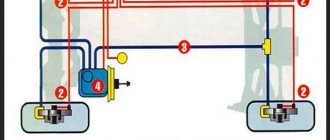
- The first step is how to connect a signal through a relay: remove the “-” terminal from the battery.
- Next, you need to remove the sound signal and install a relay in its place.
- Wire connection options
- A so-called “leech” is installed on the “+” wire that connected the sound signal. A wire approximately 15 cm long with male-female terminals is connected to it;
- If it is not possible to install a “leech”, you can strip the positive wire, then solder a piece of wire with a “mother” terminal to it. The soldering area must be sealed with insulating tape or pre-applied heat shrink.
- Next, the “+” wire must be connected to the relay. To do this, a wire with a newly formed process is connected to the 86th and 30th contacts.
- Let's move on, figuring out how to connect a signal to a VAZ or any other car. Now you need to connect the remaining negative wire to the relay. To do this, you need to use pin 85.
- An audio signal is connected to the remaining 87th contact of the relay.
- Last step: put the “-” on the battery.
DIY turn relay
Sometimes situations arise when the standard turn signal relay fails and a new device cannot be purchased. In such a situation, you can try to make a turn signal relay with your own hands to provide the car with the necessary signals. The simplest electronic devices that you can make yourself are simple and easy to use, operate smoothly and reliably. High precision is achieved through the use of PWM controllers used in all circuits.
The simplest replacement for an electromagnetic relay is designed for a maximum load power of 150 W. It is connected to the positive air gap. If the IRFZ44 field switch is replaced with the IRF3205 model, 200 W can also be connected. This simple circuit guarantees high accuracy. The blinking frequency does not depend on the power of the lamps, so LED, halogen and other lamps can be included in the circuit.
The blinking frequency is directly related to the capacitance of the capacitor. As the capacity increases, the indicator will blink less frequently, and conversely, decreasing the capacity will cause it to blink faster. The low-power 1n4148 diode can be replaced with any similar element. When the circuit reaches 80 W, a small amount of heat is observed in the FET area. This means it is ready to use.
There is another simple gear shift relay circuit with a coil - simple, reliable and inexpensive. It is capable of turning on both conventional and LED lamps and is designed for a voltage of 12 V. The contacts are connected according to the principle of a regular switch, that is, in series with the light bulb. The LED is installed in the circuit as an indicator during commissioning. The device parameters are regulated by changing the resistance of the resistor.
Types of Voltage Regulators
Having understood what types of these devices there are, what their features and properties are, a complete understanding of the procedures carried out during testing will come. This will also give the answer to what scheme, in what way and how to check the generator voltage regulator. There are two types of regulators:
In the first case, it is meant that the regulator housing is combined with the brush assembly directly in the generator housing. In the second case, the regulator is a separate unit, which is located on the car body, in the engine compartment, and wires from the generator go to it, and wires from it go to the battery.
A special feature of the regulators is that their housings are non-separable. They are usually filled with sealant or special resin. And there is no particular point in repairing them, since the device is inexpensive. Therefore, the main problem in this regard is to check the generator voltage regulator relay. Regardless of the type of regulator, the voltage symptoms will be the same.
The simplest way to check the generator voltage regulator
The simplest method of checking the regulator is to measure the voltage at the battery terminals with a multimeter. However, it is worth immediately making a reservation that the algorithm given below does not give a 100% probability of failure of the regulator. Perhaps the generator itself has failed. But the advantage of this method is that it is simple and there is no need to dismantle the device from the car. So, the algorithm for checking the generator voltage regulator with a multimeter is as follows:
- Set the tester to DC voltage measurement mode at a limit of about 20 V (depending on the specific model, the main thing is that it displays values up to 20 V as accurately as possible).
- Start the engine.
- Measure the voltage at the battery terminals in idle mode (1000. 1500 rpm). If the regulator and generator are working properly, the value should be within 13.2. 14 V.
- Increase the speed to 2000. 2500 rpm. In the normal state of the electrical circuit, the corresponding voltage will increase to 13.6. 14.2 V.
- When the speed increases to 3500 rpm and above, the voltage should not exceed 14.5 V.