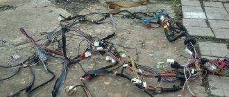
Not all drivers know what a VAZ 2107 charging relay is, and besides, this device is rarely remembered. The charging relay is a voltage regulator or “chocolate bar” located in the generator. Owners of the "Seven" pay attention to this detail only after problems begin with the battery not charging. So that there is no need at the moment, which negatively affects the engine, it is necessary to periodically monitor the operation of the charging relay.
Purpose of the regulator relay VAZ 2107 injector and carburetor
The main purpose of the voltage regulator relay on the VAZ 2107 and any other car is to maintain a stable and sufficient charging current for the on-board network and the car battery, as well as to level out voltage surges in the generator running around. When the generator rotates at different frequencies, voltage fluctuations occur. When the power drops below 12V, the battery stops charging and the entire botnet stops working at 100%. If the voltage exceeds 16 volts, this can lead to boiling of the battery, as well as failure of on-board devices.
On the first carburetor-type VAZ production cars, the voltage regulator is located on the left arch of the engine compartment. Such devices are also called external, since they were installed outside the generator structure. To be more precise, the generator has a brush mechanism and is controlled by a circuit board installed outside the product.
Most VAZ 2107 cars of carburetor and injection type are equipped with generators with built-in charging relays. The charging relay on such VAZ 2107 cars is located directly on the generator side opposite the pulley.
To maintain an acceptable battery charge, the alternator must supply between 13.6 and 14.6 volts. The voltage regulation circuit is carried out through an electrical circuit, which is located on a printed circuit board (chocolate bar) or in the form of a single semiconductor module (tablet) with brushes. The coil located inside the generator usually cannot respond adequately to ambient temperature due to its location near the running engine. The built-in relay is sometimes replaced with a three-stage voltage regulator, due to the increased efficiency of the product due to manual adjustment of the output voltage.
How to check the charging relay on a VAZ 2107
If you suspect that the voltage regulator relay is faulty, you should first check the voltage at the battery terminals with the vehicle running. The supply voltage must be at least 13 and not higher than 14.6 Volts. The reasons for this increased or decreased voltage may be due to the following factors:
- charge controller malfunction;
- failure of the generator itself;
- lack of contact in the electrical connections of the battery or generator.
To check the health of the chocolate, you need to remove it from the generator. This must be done by unscrewing two bolts.
It is important to know! Before removing the device, do not forget to unscrew the negative terminal from the battery.
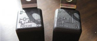
To check the functionality of the product, you must connect a voltmeter or test lamp, as well as an adjustable power supply for 12-22 Volts. You can use a power supply with a variable resistor. The regulator relay is controlled by connecting the negative wire from the regulated source to ground or to terminal “Ш”. The positive wire of the power supply must be connected to the "B" terminal. A voltmeter or lamp is connected to the brushes or relay output. If the product is subject to repair, when a voltage of 12 to 14 volts is applied, the light will light up or the voltmeter will show similar values. If you apply more than 16 volts, the light should go out. If the bulb glows constantly, it can be assumed that the product has been pierced. The absence of a light bulb indicates an open circuit in the relay. In both cases, the regulator cannot be repaired and must be replaced.
How can I check the performance of a product without removing it from the car? To do this, connect a voltmeter to the battery terminals, then start the engine. If the voltmeter reading is below 12.7 V or above 14.6 V, the probability of chocolate failure is 95%. Replace the product with a new one and then check the voltage.
It is important to pay attention to the brushes of the product, which must protrude from the brush assembly at a distance of at least 5 mm. If the brushes are worn, the brush assembly must be replaced.
Product replacement
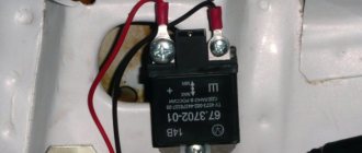
Replacing the voltage regulator on a VAZ 2107 is very simple. To do this, unscrew the two bolts with a screwdriver or wrench, depending on the generator model, then disconnect the terminal, then remove the part itself, which looks like the one shown in the photo below.
Replacing the voltage regulator is quite simple, without even removing the generator. Before carrying out work, be sure to unscrew the negative terminal from the battery to avoid a short circuit.
It is possible to replace the product with a similar one, but it is recommended to use a three-stage regulator. It provides more reliable stabilization and regulates three levels of output voltage.
The brush mechanism is installed in place of the standard relay, and the box with the board and three-position switch is fixed anywhere in the engine compartment, but always with a ground connection on the steering rod. After replacement, set the switch to the appropriate position depending on the temperature conditions.
If you suddenly notice that your VAZ 2107 car has lost battery power, this malfunction must be corrected immediately. If you use the car without charging, the battery will drain very quickly and you will have to use a tow truck or tow truck.
To find the reason why the battery does not charge and how to solve this problem, you need to start with theory.
Generator device
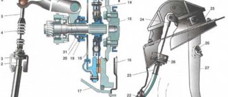
The design of a car generator implies the presence of its own rectifier and control circuit. The generating part of the generator, using a stationary winding (stator), generates three-phase alternating current, which is then rectified by a series of six large diodes and the direct current charges the battery. Alternating current is induced by the rotating magnetic field of the winding (around the field winding or rotor). Next, the current is supplied to the electronic circuit through the brushes and slip rings.
Generator structure: 1.Nut. 2. Washer. 3.Pulley 4.Front cover. 5. Distance ring. 6.Rotor. 7.Stator. 8.Back cover. 9.Casing. 10. Gasket. 11.Protective sleeve. 12. Rectifier unit with capacitor. 13.Latch holder with voltage regulator.
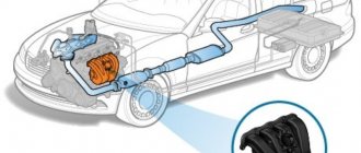
The generator is located at the front of the car engine and is started using the crankshaft. The connection diagram and operating principle of a car generator are the same for any car. There are, of course, some differences, but they are usually associated with the quality of the manufactured product, the power and the layout of the components in the motor. All modern cars are equipped with alternating current generator sets, which include not only the generator itself, but also a voltage regulator. The regulator equally distributes the current in the excitation winding, and it is due to this that the power of the generator set itself fluctuates at a time when the voltage at the power output terminals remains unchanged.
The principle of operation of a car generator
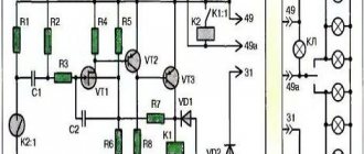
Connection diagram for the VAZ 2110-2115 generator
The alternator connection diagram includes the following components:
- Battery.
- Generator.
- Fuse block.
- Ignition.
- Dashboard.
- Rectifier block and additional diodes.
The principle of operation is quite simple: when the ignition is turned on plus through the lock, the ignition goes through the fuse box, light bulb, diode bridge and goes through a resistor to minus. When the light on the dashboard lights up, then the plus goes to the generator (to the excitation winding), then during the process of starting the engine, the pulley begins to rotate, the armature also rotates, due to electromagnetic induction, electromotive force is generated and alternating current appears.
Next, the diode passes plus into the rectifier block through a sine wave into the left arm, and minus into the right arm. Additional diodes on the light bulb cut off the negatives and only positives are obtained, then it goes to the dashboard assembly, and the diode that is there allows only the negative to pass through, as a result the light goes out and the positive then goes through the resistor and goes to the negative.
The principle of operation of a car DC generator can be explained as follows: a small direct current begins to flow through the excitation winding, which is regulated by the control unit and is maintained by it at a level of slightly more than 14 V. Most generators in a car are capable of generating at least 45 amperes. The generator operates at 3000 rpm and above - if you look at the ratio of the size of the fan belts for the pulleys, it will be two or three to one in relation to the engine frequency.
To avoid this, the plates and other parts of the generator rectifier are partially or completely covered with an insulating layer. The heat sinks are combined into a monolithic design of the rectifier unit mainly by mounting plates made of insulating material, reinforced with connecting bars.
Next, let's look at the connection diagram for a car generator using the example of a VAZ-2107 car.
Reasons for the battery not charging
In order for the ignition system and other electrical circuits of the VAZ 2107 to work properly, the voltage in the on-board network must be constant. When the motors are not running, the battery maintains constant voltage. After starting the engine, the car's generator is activated, charges the battery and maintains the on-board voltage within 13.6-14.2 volts. Regardless of the speed, the voltage on the generator must remain constant. This is ensured by a relay regulator, which, depending on the speed, changes the voltage in the generator circuit. If the voltage drops below the permissible level, the winding current increases, increasing the output voltage and vice versa.
If the VAZ 2107 is not charging, possible reasons may be the following:
- poor contact or open circuit in the generator output voltage excitation circuit;
- faulty relay regulator;
- broken generator belt.
Troubleshooting a generator should first begin by identifying the cause of insufficient battery charge.
How to find the reason for the battery not charging
The first sign of insufficient charge is if the warning light on the instrument panel comes on or if the voltmeter needle is not in the green zone when the engine is running. More precisely, you can check the voltage on the battery with a multimeter.
When the engine is running, the voltage on the battery should be -13.9 ± 0.3 V. If the battery is not charged, the voltage will be about 12 V.
Caution: To avoid damage to the ECU and governor relays, do not remove the battery terminals while the engine is running.
Overvoltage or undervoltage in the vehicle's electrical system will damage the battery. In the first case, the electrolyte evaporates, in the second it is discharged, which leads to battery failure.
To find the problem and fix it, you will need the following tools and accessories:
- control lamp 12 V;
- multimeter;
- knife;
- flat screwdriver;
- pliers;
- sandpaper.
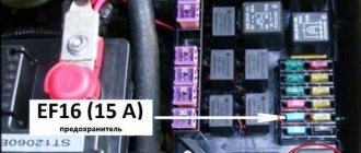
Blown fuse
A failed dashboard light may be caused by a blown fuse. In this case, several devices usually fail at once. If such a symptom appears, you just need to check the fuse. It is located in the mounting block.
Mounting fuse block VAZ 2107
You can find it using the diagram on the block cover. To check, the fuse is removed from the mounting block. The easiest way is to install a known good fuse. If this is the reason, then the light should light up when the ignition is turned on. You can also check the fuse by measuring the resistance with a multimeter.
Troubleshooting battery failure
The first step is to check the tension of the alternator belt - it is what drives the alternator and coolant pump, so this malfunction can also manifest itself in the form of engine overheating.
If the VAZ 2107 battery charging light does not light up and the voltmeter shows normal on-board voltage and the battery is not charging, the reason is clearly in the contacts at the terminals.
It is necessary to remove the clamps from the battery and sand them with sandpaper. If the charge does not appear, it is necessary to measure the voltage at output “30” of the generator with the engine running. If the voltage readings on this output and the battery are very different, you need to clean the contacts and check the wire going from the generator to the battery. If the wire is faulty, it must be replaced.
If the voltage in the on-board electrical network is within acceptable limits when the engine is running, but drops when the headlights are turned on, the reason is the weak tension of the alternator belt. A weak belt will slip under greater load. The correct belt tension is when, with a force of 10 kgf, it should bend by 12-17 mm.
Another reason for the lack of charge could be a short circuit or break in the stator or rotor winding, as well as a failed rectifier diode on the generator.
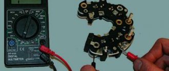
Diodes can be tested using a test light or multimeter to check their resistance. To check the diodes using a test lamp, remove the “+” terminal from the battery and connect the test lamp with one end to the positive terminal, and the other end must be touched in series to the three bolts shown in the figure below. Then perform the same operation, only with the “-” terminal. If the test lamp lights up, the diode being tested is broken.
If one of the diodes fails, the diode bridge assembly must be replaced.
A malfunction of the stator winding can be determined with a multimeter by measuring the resistance between the rectifier unit mounting bolts. If there is no contact between them, then the winding is broken. In this case, the winding or generator assembly is changed.
Probably the most common cause of generator failure is brush wear. To check them, you need to remove the brush assembly. The length of the brushes must be greater than 5 mm, otherwise they must be replaced. Brushes can also become jammed or twisted in the sockets.
Note: the injection generator is no different from the generator of the carburetor version of the VAZ 2107. All proposals for repair and inspection of the generator are relevant for both modifications of the car.
The battery does not charge and can it completely drain at night with the headlights on? Family story! It is possible that the whole issue is a faulty generator voltage regulator. You can only find out by checking it.
Low battery
Another common reason why the battery warning light does not light up when the ignition is turned on in a VAZ 2106 - 2107 is a weak battery.
If, at the same time that the battery light does not light up, the dashboard instruments do not turn on or are dimly lit, then this is a clear sign of a low battery. The problem can be “cured” by simply charging the battery.
Good battery
However, not all so simple. The discharge of a car battery may not occur because the owner did not have time to charge it in time or forgot to turn off the headlights. A problem with a battery becomes dangerous if the cause lies in the generating device. As you know, the battery must be charged while the car is moving, otherwise it will discharge quite quickly. And this function falls on the generator. But if the latter is faulty, then problems arise.
Thus, a seemingly trivial reason may indicate a damaged car generator, which performs many useful functions. Obviously, a thorough diagnosis should be carried out, the cause should be found and eliminated.
Voltage regulator VAZ 2107 - purpose and first signs of malfunction
The voltage regulator is designed to automatically maintain current at such a value that the voltage generated by the generator falls within certain specified limits, regardless of the speed of the generator shaft (motor speed) and the current consumption of the grid electric vehicle. In VAZ 2107 cars, as a rule, an electronic voltage regulator is installed on the generator.
It is extremely rare in some models to find an old-fashioned device - a relay regulator. They were installed on generators 37.3701, produced before 1996, and on G-222. The device is first tested on a racing car. This requires a voltmeter capable of measuring DC voltage. The device must be equipped with a scale for values up to 15-30 V and have an accuracy class of at least 1.0. After starting the VAZ 2107 engine, you are allowed to work with the headlights on for 15 minutes at medium speed.
Then the voltage at the generator output is measured. To do this, the positive probe of the device touches terminal “30” on the generator, and the negative probe touches ground (generator or car - the same, the same). The voltmeter should show a voltage in the range of 13.6-14.6 V. If the measurement result is higher or lower than specified, and the car systematically operates, overloading or undercharging the battery, then most likely the regulator is faulty and should be replaced.
Checking the removed voltage regulator
To check the condition of the regulator, it must be removed. It is better to test the assembled device using brushes and brush holders. This will allow you to immediately detect:
- poor contact between the terminals of the brush holder and the voltage regulator;
- breakage of outgoing brush conductors.
Electronic devices are produced already assembled with brush holders and brushes as one unit. A relay regulator must be connected to the removed brushes.
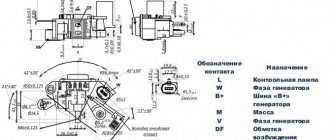
A voltmeter or a 12 V lamp with a power of 1-3 W is connected to the brushes of the device removed from the generator 37.3701. For the regulator from the G-222 generator, the connection is made to the “V” and “W” terminals. At terminals “B”, “C” (when they exist), the device is connected to the “plus” of the power supply, and to the ground – “minus”. First, a voltage of 12-14 V is applied, then 16-22 V. A sign of the device’s operability will be the lighting of the lamp (deviation of the voltmeter needle) in the first case and extinguishing (zeroing) the voltmeter) in the second.
When the light comes on in both cases, it means there is a problem with the device. If in both cases the lamp does not light up, it means that there is no contact between the regulator terminals and the brushes or there is an open circuit in the device. Another reason for incorrect tension adjustment could be a worn or stuck brush. They must protrude from the housing of the electronic device or the brush assembly of the relay regulators by at least 5 mm.
Replacing the voltage regulator VAZ 2107
If the regulator is faulty, the brushes are worn out or jammed, the device must be replaced. This cannot be fixed. For a relay-regulator, in the event of a brush malfunction, it is sufficient to replace only one group of brushes. Usually they change it to a new electronic one, but you can install a three-level one, like 67.3702-02. They provide better voltage stabilization than standard regulators, taking into account the ambient temperature and vehicle operating conditions.
They are called three-level because of the 3 voltage regulation modes built into them. Their selection is carried out manually using a switch on the regulator, which is installed separately from the generator itself in a convenient protected place. The device is connected to the generator by wires through the brush assembly supplied with the regulator.
What does it look like and where is it installed?
Now let's find out where the VAZ-2107 charging relay (carburetor) is located. Initially, this device was placed away from the generator on the arch under the hood (on the left side). On newer “sevens” equipped with an injection system, the voltage regulator was combined with a brush assembly.
The first voltage regulators were based on electromagnetic relays; they worked quite slowly and required constant intervention. The problem is that mechanical elements wear out very quickly. In addition, it was constantly necessary to adjust the gaps in the relay. Modern semiconductor devices operate silently, quickly, without electromagnetic relays. One silicon crystal can perform the functions of several mechanical relays.