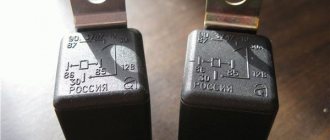
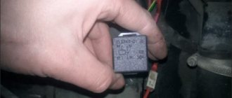
Unlike previous “classic” models, the VAZ 2107 has an additional element in the starter control circuit - a starter relay. Like any car part, the relay can fail, making it impossible to start the engine. You can identify and fix the malfunction yourself; to do this, it is enough to know where the starter relay is located on the VAZ 2107 and have a minimum of tools for checking and replacement.
Why do you need a VAZ 2107 starter relay?
The starter traction relay on all classic models, except the VAZ 2107, was switched on directly through the ignition switch. The problem is that when it is turned on, a current of more than 15A passes through the contacts on the ignition switch, which over time leads to their oxidation, heating and failure. To reduce the current passing through the ignition switch when the starter is turned on, the designers of the “Seven” provided an additional element - the VAZ 2107 starter relay. The small current required for its operation does not harm the contacts of the ignition switch, and the relay itself more reliably switches the power to the starter traction relay . Often, owners of older “classic” models, tired of regularly changing the contact group of the ignition switch, independently install an additional relay that allows them to increase the service life of the contacts responsible for turning on the starter.
Where is the starter relay located on the VAZ 2107
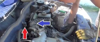
The designers provided for the installation of a starter relay on the VAZ 2107 on the right side of the engine compartment. It is attached directly to the right wing, for which a stud is installed on the wing, onto which the relay mounting nut is screwed.
The easiest way to find it is to trace where the wires from the starter traction relay go.
Types and design of electric starter relay
There are three types of starter relay:
- blocking (preventing the device from starting when the engine is running);
- unloading (converting lower currents into stable 12 V);
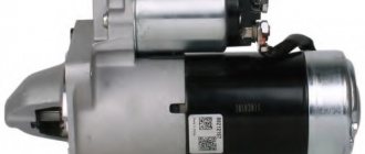
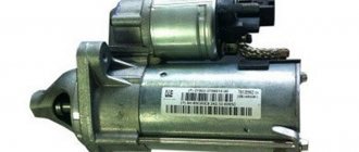
- retractor (traction), which is attached directly to the starter.
The first two are certainly important, but they are not installed on every car, unlike the “traction” one, without which the engine will not start.
The traction electromechanical relay is responsible for:
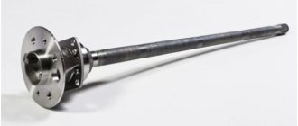
- The bendix is thrown into engagement with the flywheel.
- Closing and holding the bridge between the “plus” of the relay and the starter.
- Stable power supply to the brush assembly of the electric starter.
- Timely shutdown of the trigger mechanism.
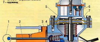
Starter solenoid relay diagram
Inside, it is arranged simply: under the metal body there is a two-winding coil with a core. On the one hand, the body has a protruding rod (the pulling end of the armature), on the other, an ebonite cover with three terminals (2 powerful contact bolts and one “pin”). The lower bolt is connected to the plus of the electric starter by a power wire (oblique). The armature - a metal core - “walks” longitudinally inside two windings (coils): “retracting” (VO) and “holding” (CU). When retracted, it presses on a movable electrode, at the end of which a spring-loaded copper contact plate is attached. At the end of the armature (core) stroke, the plate is pressed against the “nickels” of the bolts, closing a short circuit - from one to the other, and then to the electric starter brushes.
The edge of the core is connected to a fork lever that moves the Bendix gear forward. In the non-working position, it protrudes far from the body, and when current is supplied to the pulling coil, it goes under it, “pulling” the upper edge of the “fork” behind it. Swinging on the axis, its lower edge moves forward - carrying out, through the driving clutch, the Bendix (gear with a freewheel) into engagement with the teeth on the flywheel crown. When this happens, a metallic knocking or clicking sound is heard.
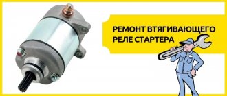
How to check the VAZ 2107 starter relay
To check the functionality of the relay, you need a voltmeter or “control”. The functionality check is performed as follows:
- remove the wire block from the relay; check whether the contacts on the relay and the block are oxidized;
- clean contacts if necessary;
- make sure there is ground on the wire going to contact “86” of the relay;
- check whether voltage appears on the wire going to terminal “85” of the relay if you try to start the car with the key;
- make sure that when the ignition is turned on, voltage is supplied to the wire going to terminal “30”;
- if there is voltage at the terminals, the problem is in the relay, not in the power supply;
- remove the starter relay from the car;
- make sure that when voltage is applied to terminals “85” and “86”, the contact between “30” and “87” relay terminals is closed.
If the relay does not operate, it must be replaced with a new one.
Why does the solenoid relay break?
The main parts of the relay: body, contacts, armature, magnet with windings, return spring. When an electric current enters the magnet's retractor winding, an electric field arises. It attracts an anchor, which moves into the core. The latter, using the lever, moves the Bendix gear forward, forcing it to come into contact with the flywheel teeth.
Next, the core, reaching the end, closes the contacts through which current begins to flow to the holding winding of the magnet. The drive is turned on, which spins the starter shaft, transmitting force through the Bendix gear to the flywheel, which spins it. As soon as the engine starts, the current to the relay stops flowing, the magnet turns off, and the return spring returns the shaft and gear to its original position.
bendix gear
What malfunctions can occur during operation of the traction relay on VAZ-2106 and 2107 vehicles?
- Knock. It can occur if the battery does not have a charge, the terminals have oxidized, the connection is faulty, or the magnet holding winding is not connected to ground as a result of its damage.
- Lack of response from the solenoid relay and the starter as a whole after turning on the ignition. As in the first case, the problem is in the condition of the battery. For example, the connection of the holding winding to ground is lost, the contact between the additional and solenoid relay is broken, or the ignition switch board is burned out.
- Incorrect operation of the armature when, after turning on the relay, it does not rotate. And here, most often, the battery is to blame. This can happen if the starter contacts have oxidized or the armature winding has burned out, causing the wire to separate and the armature itself to become jammed.
Replacing the VAZ 2107 starter relay
To replace the VAZ 2107 starter relay, you will need a 10mm wrench. To replace the relay, you must perform the following steps:
- disconnect the ground wire from the battery by removing the negative terminal;
- Using a wrench, unscrew the nut holding the relay on the right wing;
- remove the starter relay;
- install a new relay;
- screw in and tighten the fastening nut with a wrench;
- connect the wire block to the relay;
- connect the ground wire to the battery.
This completes the replacement of the VAZ 2107 starter relay. It remains to check its operation by turning the ignition key.
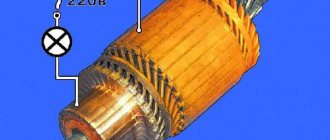
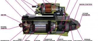
Starter: device and principle of its operation
In all cars, including the VAZ-2107, the starter performs one of the main functions - it starts the engine. To start the engine, you need to turn the crankshaft and thus create a flash of the fuel mixture in one of the cylinders. For this, a starter is needed - an electric motor in which alternating current is constantly present.
When the ignition switch contacts close, current flows through the windings. The electromagnet core retracts, and the lever connected to it moves the Bendix gear. At the same time, the core creates pressure on the plate, which closes the contacts at the moment the gear engages with the flywheel. The current through the closed contacts enters the motor winding and creates a magnetic field that rotates the crankshaft. When the engine is already running, the starter must be turned off. The key in the ignition switch is turned back, the magnetic field disappears, and the device goes into a resting state.
Structurally, the starter consists of the following elements: an electric motor, a retractor relay and an overrunning clutch with a gear (Bendix). Each component performs a specific function, and if something fails, the entire system does not work.
Electrical equipment VAZ-21074
- 1- block headlights;
- 2- side direction indicators;
- 3- rechargeable battery;
- 4- starter activation relay;
- 5- carburetor electro-pneumatic valve;
- 6- carburetor microswitch;
- 7- generator 37.3701;
- 8- gearmotors for headlight cleaners*;
- 9- fan motor activation sensor;
- 10- electric motor of the engine cooling system fan;
- 11- sound signals;
- 12- ignition distributor;
- 13- spark plugs;
- 14- starter VAZ-21074;
- 15- coolant temperature indicator sensor;
- 16- engine compartment lighting lamp;
- 17- low oil pressure indicator sensor;
- 18- low brake fluid level indicator sensor;
- 19- windshield wiper gearmotor;
- 20- carburetor electro-pneumatic valve control unit;
- 21- ignition coil;
- 22- electric motor of the headlight washer pump*;
- 23- electric motor of the windshield washer pump;
- 24- mounting block;
- 25- windshield wiper relay;
- 26- hazard warning and direction indicator relays;
- 27- brake light switch;
- 28- reversing light switch;
- 29- ignition relay;
- 30- ignition switch;
- 31- three-lever switch;
- 32- alarm switch;
- 33-plug socket for a portable lamp**;
- 34- heater fan switch;
- 35 - additional resistor of the heater electric motor;
- 36 - indicator lamp for turning on the heated rear window;
- 37 - indicator lamp for insufficient brake fluid level;
- 38 - signaling unit;
- 39- heater fan electric motor;
- 40 - glove box lighting lamp;
- 41 - lamp switch on the front door pillars;
- 42- switch for alarm lights of open front doors***;
- 43- alarm lights for open front doors***;
- 44- connecting block;
- 45- cigarette lighter;
- 46- watch VAZ-21074;
- 47- switch for instrument lighting lamps;
- 48- diode for checking the serviceability of the warning lamp for insufficient brake fluid level;
- 49 - fuel level indicator;
- 50 - fuel reserve indicator lamp;
- 51- speedometer;
- 52 - turn signal indicator lamp;
- 53- indicator lamp for closing the carburetor air damper;
- 54 - battery charging indicator lamp;
- 55- carburetor air damper closed warning switch;
- 56 - instrument cluster;
- 57- econometrician;
- 58- courtesy light switches on the rear door pillars;
- 59 - coolant temperature indicator;
- 60 - tachometer 21074;
- 61- parking brake indicator lamp;
- 62 - low oil pressure indicator lamp;
- 63- high beam indicator lamp;
- 64- indicator lamp for turning on external lighting;
- 65-voltmeter;
- 66- parking brake indicator switch;
- 67- switch for external lighting lamps;
- 68- rear window heating element switch with backlight;
- 69- switch for rear fog lights with on/off indicator*;
- 70 - fog light circuit fuse;
- 71- lampshade;
- 72 - rear lights VAZ 21074;
- 73 - level indicator and fuel reserve sensor;
- 74- pads for connecting to the rear window heating element*;
- 75 - license plate lights.
Removal and Replacement Guide
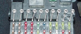
Fuse and relay block VAZ 2107
If you do not know how to remove and disassemble the mounting device or safety elements and how to replace the old unit with a new one, then we will consider each instruction in turn.
Changing fuses yourself
Before you begin replacing the safety devices located in the main unit, you must turn off the ignition and battery terminals under the hood.
The replacement procedure is carried out as follows:
- Find the installation location of the device. There are latches on the plastic cover of the block; press them. After removing the cover, you will be able to see a diagram printed on the reverse side, which indicates the location and purpose of all used elements.
- Then you need to identify which device has failed and needs to be replaced. Sometimes a breakdown can be determined visually - the component itself may be burnt out, sometimes a broken thread is clearly visible in it.
- Under the cover of the device you will see tweezers, which can be used to remove the device. If you don't have tweezers, you can use pliers.
- Remove the burnt out element and replace it with a new one, then replace the cover and connect the battery terminals (video filmed and published by the AVTOCLUB_22 channel).
Replacing fog lamp fuses
If the fog optics break down, you should first diagnose the operation of the device. The component is located inside the car.
To check and replace, follow these steps:
- First you will need a Phillips screwdriver, use it to remove the two switches located in the middle of the console, near the audio system.
- Using a screwdriver, you will need to press out two fasteners.
- Then remove the plastic insert.
- You can now remove the fuse housing. Remove the protective cover of the device and replace the part with a new one.
1. Remove the two switches with a screwdriver.
2. Press on the pad fasteners.
3. Remove the insert and remove the device.
Changing the fuse box
Removing and replacing the block with components is done as follows:
- First, open the engine compartment of your car and remove the air filter housing. Unscrew the nuts that secure the housing using a Phillips screwdriver.
- Then under the device you will be able to see a plug with cables connected to the device, you need to unplug it. The product body itself is marked in colors; it corresponds to the color of the connected connectors. By taking these plugs into account, the need to label cables can be avoided.
- After this, you should climb into the vehicle interior and remove the shelf, which is located under the control panel. After this, unscrew the bolts that hold the glove box housing.
- Next, disconnect the plug with cables connected to the connectors directly on the device. Once you do this, you will be able to see the color coding.
- Using a wrench, remove the bolts that secure the block itself. Please note that the outermost screw on the case is hidden, so you will not be able to see it immediately.
- At the end, remove the block with the devices, now the device can be replaced. Installation of a new device, as well as assembly of components, is carried out in the reverse order.
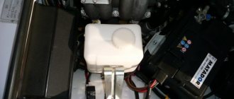
The mounting fuse block contains some electrical control elements of a VAZ car and most fuses that protect electrical circuits from short circuits and overloads. It is located in the engine compartment on the left side, immediately on the metal partition between the engine compartment and the cabin. Here is the photo (top left):
Is it possible to fix it?
Relays for starters used in Zhiguli cars received identical parts in view of completely identical tasks. The only inconvenience is that, depending on the supplier manufacturer and the modification of the car itself, the attachment points of the units may differ slightly from each other, and some differences in internal components are allowed.
Unit mounting location
There is no point in repairing the devices; for VAZ-2107 and 2106 it is easier to purchase the entire starter assembly. But, if there are financial difficulties, you can only replace the relay. And this is the order in which you should proceed. Be sure to disconnect the battery first! The starter is installed in the car electrical network in such a way that shorting its contacts can lead to burnout of the entire car wiring.
Purchase of VAZ-2106 starter assembly
Then remove and thoroughly clean the starter from dirt. This is necessary to ensure that random particles do not get into the electrical winding and prevent a short circuit. Now we disconnect the contact from the bolt of the traction relay, unscrew the tightening screws and remove the part.
Modern cars are equipped with such a part as a starter, the main purpose of which will surprise no one. Before its invention, a special L-shaped lever was used to start cars. With its help, the driver, standing in the middle of the car, manually cranked the crankshaft, and the engine started. This starting lever is called a “crooked starter”. Today, the VAZ 2107 is equipped with an electric starter, which allows you to start the engine by turning the ignition key while sitting in the passenger compartment. One of its most important mechanisms is the solenoid relay, the purpose of which we will learn in more detail.
What does a car need a traction relay for?
The starter solenoid (or traction) relay is a fairly important device. At the dawn of the automotive industry, the role of this unit was played by a long handle and the driver himself, who, by inserting it into the hole in the flywheel, accelerated the engine. Later, cars acquired starters with retractor relays, which are designed to provide initial force to the gear that drives the motor shafts.
Starter traction relay
In the designs of most cars (as in “classic” VAZ models), the retractor relay is a small unit mounted directly on the starter housing itself. His tasks are the following:
- moving the bendix gear to engage the flywheel teeth and returning it to its original position after the engine starts running;
- energy distribution between the starter drive and the electromagnet;
- synchronous operation of the starter during engine starting.
The starters installed on the VAZ-2106 and 2107 starters are actually the same. Regarding the solenoid relay, we can say that it has not undergone any significant changes. But there is one more detail with the same name, which is considered the difference between these two models. This is the starter activation relay: on early VAZ models it is not there at all, but in 2107 it appears.
Relay for turning on the VAZ-2107 mechanism
Before this innovation, control from the ignition switch went directly to the solenoid relay.
It is worth saying a few words about this mechanism. The starter activation relay is located some distance from the starting mechanism itself, so you should look for it by wires. Naturally, with each new release of VAZ, its location changed. But when it first appeared in 2107, the starter relay was located on the right mudguard in the engine compartment. It is easy to remove and replace with a 10mm wrench. But the traction relay still does more work and fails much more often, so let’s talk about it in more detail.
Diagram and description
The design of the VAZ retractor relay is shown in the diagram and it hardly requires explanation. The solenoid formed by the cylindrical retractor coil and the armature pushes the starter fork and meanwhile moves the contact plate that closes the starting contacts of the starter motor. The relay itself is a dielectric container with contact plates mounted in it. On the outside, the contacts end in a threaded part, onto which the terminals are placed and clamped with nuts.
The relay's operation is also extremely simple. When we turn the ignition key, we supply current not immediately to the starter, but to the control relay, which is located under the hood in the VAZ 2107. The contacts of the device close and pass current from the battery to the contacts of the retractor. Voltage is applied to the holding winding, which creates a magnetic field. Under its influence, the rod is simply retracted into the device body, thereby killing two birds with one stone - using a lever, it brings the Bendix gear to the flywheel crown and closes the contacts that supply current to the electric motor. As soon as the engine starts, the current supply stops, the spring returns the rod to its original position, disengaging the bendix and flywheel, breaking the contacts and de-energizing the electric motor.
Basic faults
A fairly simple and reliable design, however, given the high loads and high currents with which the mechanism has to work, various problems appear from time to time. They can be expressed either very simply, for example, the starter does not respond at all to turning the key, or as permanent problems, the cause of which is most difficult to establish.
The main malfunctions of the solenoid relay are listed below, but the difficulty is that the malfunctions can either be combined with each other or be a consequence of the usual loss of contact at the battery terminals. Therefore, troubleshooting must begin from afar. However, here are the problems:
- Short circuit of the holding or retracting windings, then the fuses will simply burn or the control relay will simply not supply voltage to the contacts;
- deposits on contacts;
- winding breakage;
- distortions or damage to the return spring;
- physical damage to the relay housing or parts.