Where is the starter relay located?
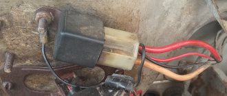
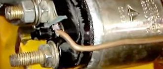
It is located in the engine compartment and is attached there to the car body using one single nut; in the photo below this relay is indicated by a red arrow, and the blue arrow shows the air pipe behind which this relay is located.
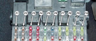
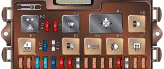
Diagram of the mounting fuse block for VAZ 2109, 2108, 21099 (block 17.3722)
In the diagram: (the outer number in the designation of the wire tip is the number of the block, and the inner number is the conventional number of the plug)
K1 — rear window washer time relay; K2 - relay-interrupter for direction indicators and hazard warning lights; KZ - windshield wiper relay; K4 - relay for monitoring the health of the lamps (contact jumpers are shown inside, which are installed instead of the relay); K5 - headlight high beam relay; K6 - relay for turning on headlight wipers; K7 — power window relay; K8 - horn relay; K9 - relay for switching on the electric motor of the engine cooling fan; K10 — relay for turning on the heated rear window; K11 - relay for low beam headlights.
When do you need to change the starter relay?
There are some people who either don’t know the electrical part of their car well, or simply never look at this relay (They say it lasts forever and never breaks), we just want to say that many people, when they see that their car won’t start with the key, they immediately jump into the starter, they remove it at the beginning, then replace the parts on it, remember for the future, you should always start with small and easily accessible things and only then go to hard-to-reach things and check them and change them if a malfunction is detected.
Note! If the starter relay fails, as we have already said, the car will not start and thereby respond to turns of the key in the ignition switch, the same will happen if the battery is weakly charged, and therefore if you suspect it, either charge it or change it to a new one if it is already very worn out, in addition, exactly the same situation (the car will not start) can occur due to the ignition switch, namely because of its contact group, but on cars with a starter relay, this rarely happens, because that the relay also unloads the contacts at the ignition switch and thus the contacts are less likely to burn out, but you can still read about how to check the contact group of the lock in the article entitled: “Replacing the ignition switch and its contact group on a VAZ”!
Fuse and relay box
The main block with fuses and relays is located under the hood, in the rear, in the installation compartment on the left, under the protective cover.
Option 1
Photo - example
Scheme
Fuse designation
| 1 | 8A Right fog lamp |
| 2 | 8A Left fog lamp |
| 3 | 8A Headlight cleaners (at the moment of switching on), headlight cleaner switch-on relay (contacts), headlight washer switch-on valve |
| 4 | 16A Coil of the radiator fan relay, electrical circuit of the switch and heater motor |
| 5 | 3A Hazard switch in turn signal mode, turn signal switch, turn signal switch, turn signal indicator light, turn signal indicator light, reverse optics switch, reverse lights, tachometer, voltmeter, gasoline level indicator, gasoline level sensor, gasoline level indicator light , coolant temperature indicator, temperature sensor, warning lamp and emergency oil pressure sensor, brake emergency lamp, brake system hydraulic switch, hand brake switch |
| 6 | 8A Brake light switch and bulbs, interior lighting |
| 7 | 8A Room lighting lamps, indicator lamp for turning on the dimensions, illumination lamp for the heater and cigarette lighter handles, glove box illumination lamp, switch and instrument panel illumination lamp |
| 8 | 16A Signal, signal switch, radiator fan motor |
| 9 | 8A Left side lamp, left rear side lamp |
| 10 | 8A Right side lamp, right rear side lamp, fog light switch, fog light indicator light |
| 11 | 8A Turn signal switch and breaker, turn signal lamps, warning lamp in emergency mode |
| 12 | 16A Cigarette lighter, socket for carrying lamp |
| 13 | 8A High beam right headlight |
| 14 | 8A Main beam of the left headlight, high-range optics warning lamp |
| 15 | 8A Low beam right headlight |
| 16 | 8A Low beam left headlight |
Fuse number 12 at 16A is responsible for the cigarette lighter.
Relay purpose
| K1 | Headlight wiper relay |
| K2 | Relay - turn signal and hazard warning light switch |
| K3 | Windshield wiper relay |
| K4 | Lamp health monitoring relay |
| K5 | High beam relay |
| K6 | Headlight washer relay |
| K7 | Relay for switching on glass lifts |
| K8 | Horn relay |
| K9 | Fan relay |
| K10 | Rear window defroster relay |
| K11 | Low beam relay |
Option 2
Photo - diagram
Description
| 1 | 10A Headlight cleaners (at the moment of switching on) Headlight cleaner switching relay (contacts) Headlight washer switching valve |
| 2 | 10A Direction indicators and hazard warning relay (in hazard mode) Hazard warning lamp |
| 3 | 10A Rear lights (brake lamps) Interior lighting |
| 4 | 20A Rear window heating element Relay (contacts) for turning on the rear window heating Plug socket for a portable lamp Cigarette lighter |
| 5 | 20A Electric motor of the engine cooling system fan and its activation relay (contacts) Sound signal and its activation relay |
| 6 | 30A Electric glass lifts of front doors Relay for turning on electric glass lifts |
| 7 | 30A Headlight cleaners (in operating mode) Relay for turning on the headlight cleaners (winding) Heater fan electric motor Window washer motor Rear window wiper gear motor Rear window washer timing relay Windshield and rear window washer activation valves Relay (winding) turning on the electric fan of the engine cooling system Relay (winding) ) switching on the heated rear window Indicator lamp for heated rear window Glove box lighting lamp |
| 8 | 7.5A Left fog lamp |
| 9 | 7.5A Right fog lamp |
| 10 | 7.5A License plate lights Engine compartment lamp Instrument lighting lamps External lighting control lamp Heater lever illumination panel Cigarette lighter lamp Left headlight (side light) Left rear light (side light) |
| 11 | 7.5A Right headlight (side light) Right rear light (side light) |
| 12 | 7.5A Right headlight (low beam) |
| 13 | 7.5A Left headlight (low beam) |
| 14 | 7.5A Left headlight (high beam) Indicator lamp for turning on the high beam headlights |
| 15 | 7.5A Right headlight (high beam) |
| 16 | 15A Turn indicators and relay-interrupter for direction indicators and hazard warning lights (in turn signal mode) Turn signal indicator lamp Rear lights (reversing lamps) Motor gearbox and windshield wiper activation relay Generator excitation winding (when starting the engine) Brake fluid level indicator lamp Oil pressure warning lamp Carburetor air damper warning lamp Parking brake warning lamp "STOP" indicator lamp Coolant temperature gauge Fuel level gauge with reserve warning lamp Voltmeter |
Fuse number 4 at 20A is responsible for the cigarette lighter.
Relay
| K1 | Headlight wiper relay | |
| K2 | Relay - turn signal and hazard warning light switch | |
| K3 | Windshield wiper relay | |
| K4 | Lamp health monitoring relay | |
| K5 | Relay for switching on glass lifts | |
| K6 | Horn relay | |
| K7 | Heated rear window relay | |
| K8 | High beam relay | |
| K9 | Low beam relay | |
Option 3
Scheme
Purpose
| 1 | 10A Right fog lamp |
| 2 | 10A Left fog lamp |
| 3 | 10A Headlight cleaners (at the moment of switching on) Headlight cleaner switching relay (contacts) Headlight washer switching valve |
| 4 | 20A Headlight wiper motor Headlight cleaner relay (winding) Heater motor Window washer motor Rear window wiper motor Rear window washer time relay Windshield and rear window washer activation valve Relay coil for turning on the electric cooling fan Rear window heating relay winding Rear window heating control lamp Lamp glove compartment lighting |
| 5 | 10A Turn indicators in turn indication mode and the corresponding indicator lamp Rear lights (reversing lamps) Indicator lamp for fuel reserve, oil pressure, parking brake, brake fluid level, carburetor air damper Voltmeter and indicator lamp for charging the battery Gearmotor and windshield wiper switch relay glass Generator excitation winding (at start-up) “STOP” indicator lamp Coolant temperature and fuel level indicators |
| 6 | 10A Rear lights (brake lamps) Interior body lighting lamp Electric windows and power window relay |
| 7 | 10A License plate lights Engine compartment lamp Indicator lamp for turning on side lighting Instrument lighting lamp and cigarette lighter lamp Heater lever illumination panel |
| 8 | 20A Electric motor of the engine cooling system fan and its activation relay (contacts) Sound signal and its activation relay |
| 9 | 10A Left headlight (side light) Left rear light (side light) |
| 10 | 10A Right headlight (side light) Right rear light (side light) |
| 11 | 10A Direction indicators and hazard warning relay (in hazard mode) Hazard warning lamp |
| 12 | 20A Rear window heating element and heating relay lighter Socket for portable lamp |
| 13 | 10A Right headlight (high beam) |
| 14 | 10A Left headlight (high beam) Indicator lamp for turning on the high beam headlights |
| 15 | 10A Left headlight (low beam) |
| 16 | 10A Right headlight (low beam) |
Fuse number 12 at 20A is responsible for the cigarette lighter.
The purpose of the relay is shown in the diagram.
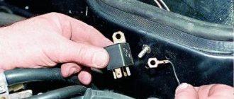
Separately, outside the unit, a starter relay is installed on some models, on the rear wall of the engine compartment.
Element Role
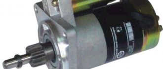
All VAZ cars, including model 2109, have a standard engine starting system, which is based on an electric starter. Here's what you need to know about him.
- A starter is a small electric motor that is connected to the flywheel of the motor via a coupling (Bendix) for a short period of time to start the rotation of the flywheel.
- Despite its small dimensions, the starter passes through itself enormous currents.
- If the starter circuit were closed directly in the ignition switch, then not a single component of the system would be able to withstand such current loads. As a result, they would burn out.
- Therefore, for these purposes, the starter is connected remotely to the battery via a relay. Its contacts are designed for high currents.
- The starter operates briefly and must be turned off after the engine starts. Otherwise, its active destruction will begin due to the influence of motor power.
- Relyushka performs these tasks perfectly. Actually, it is precisely to ensure the functioning of the system and protection against current, timely shutdown of the starter, a retractor relay is included in the design.
Element diagram
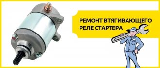
Purpose of the solenoid relay
All cars of the Volzhsky Automobile Plant use a classic engine starting system, based on an electric starter with the following device:
- The starter is a compact electric motor, which is connected to the engine flywheel using a coupling (aka Bendix) for a short time, causing the flywheel to rotate
- All this looks so simple at first glance, but in reality, ensuring the normal operation of the starter is a very difficult task, and there are two reasons for this
- The first is that although the starter has modest dimensions, during operation a current of tens and even hundreds of amperes is passed through it, and this creates some problems with its safe connection to the machine’s power circuit
- If you close the starter circuit in the ignition switch directly, then no lock, as well as other components that are included in this circuit, will simply burn out, unable to withstand the currents that arise when starting the starter (see Repairing a VAZ 2109 starter with your own hands - an opportunity to save a lot of money)
- That is why it is necessary to connect this unit to the battery remotely, using a relay that has contacts designed for high currents
- Second, the unit must operate for a short time and turn off when the engine starts, otherwise it will be destroyed, since it will not withstand the full power of the engine.
- The VAZ 2109 starter retractor, which is designed for this purpose, copes with both tasks perfectly.
Checking status
Before changing the relay, make sure that the problem with starting the engine is related to this component.
To do this, consider two situations that indicate its malfunction.
| Situation | Your actions |
| The relay makes clicks, but the armature does not spin | If there are clicks from the relay, check the condition of the armature. To do this, the terminals of the retractor relay are bridged with a large screwdriver or a piece of welding cable to the terminals at the ends. Taking a thin wire or a screwdriver can easily burn the terminals. When the armature is working, after closing the terminals, the armature will spin, which can be determined by the sound. Consequently, the solenoid relay itself has failed and requires repair. |
| The relay is completely silent | Even if there is silence after closing the terminals, the problem should be looked for in the starter. The relay no longer plays any role here. |
Having discovered that the relay has served its purpose, it must be replaced or repaired, if possible.
Consequences of a broken starter relay
If the first relay breaks, this does not happen often, but if it happens, it is most often due to overloads, or if the wires are faulty. The starter will not be able to come into working order and it turns out that the car will also fail (you won’t start it, and this is exactly the problem I encountered. Read on to find out how to fix it). The only tools we need are a 8mm wrench. This will be enough for you and you won’t need anything else! If only, just in case, take with you another wrench, for different situations.
Dismantling
There should be no problems with the dismantling process. The main thing here is to remove the starter, since the required relay is held on it. Therefore, dismantling is carried out as an assembly.
- Turn on the handbrake, disconnect the battery by removing the negative terminal from it.
- A wire with a large cross-section goes from the battery to the contact of the relay. It can be turned off by unscrewing it using a 13 key.
- Remove the thin winding power wire from the solenoid relay.
- Using the same 13mm wrench, unscrew the three mounting nuts holding the starter to the clutch block.
- You can remove the device through the bottom or top. If you chose the top, then you need to slightly rotate the starter around its axis and remove it.
- The lower output is more difficult, since here you need to remove the crankcase protection. But if parallel work is carried out that requires similar manipulations, problems will not arise.
VAZ 2109 starter repair
The most unpleasant surprise is when the car breaks down before it can start. Only the starter can be to blame for this. There is no need for diagnostics here and tricks won’t work here. A starter malfunction is visible to the naked eye and cannot be interpreted in two ways. Only dismantling and repair.
The VAZ 2109 is not a spaceship, but it’s hard to remove the starter with bare hands, and experience won’t hurt either. The car is quite reliable and easy to operate, but, as a rule, almost all nines have an impressive mileage.
Since the starter is the most loaded unit in the starting system, it fails quite often. If used incorrectly, even more so. Therefore, repairing the VAZ 2109 starter is not a tragedy, but rather a pattern.
- Starter device
- Removing the starter
- VAZ 2109 starter repair
- Solenoid relay
- Starter brushes
Starter device
Without removing the starter from the car, we are unlikely to be able to carry out a proper repair of the VAZ 2109 starter, so it must first be dismantled. But before that, let’s briefly touch on the design of the starter so that it is clear what we are talking about.
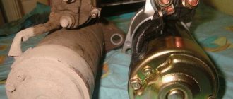
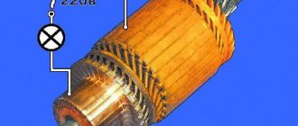
The starter is an ordinary powerful traction electric motor, consisting of the engine itself and a retractor relay - a device that is responsible for engaging the starter teeth with the teeth of the car engine flywheel. The figure shows its general structure, and we will get to know it in more detail after disassembling it:
- Manifold cover.
- Engine housing.
- Drive cover.
- Bendix.
- Electric motor shaft.
- Solenoid relay.
- Terminals.
- Armature winding output.
This is a general design of the starter, but it is already clear how the unit works - when you turn the ignition key, voltage is supplied to the starter terminals, the solenoid relay is activated, which engages the starter Bendix gear and the engine flywheel, the electric motor turns over the internal combustion engine, it starts, and after that gear retractor and bendix mechanism move the gear into place. That's it in a nutshell. Now let's start dismantling.
Removing the starter
We will be able to detect and eliminate the cause of the malfunction only when we remove and disassemble the starter. For removal we will need the usual tools and a set of sockets. We carry out the process in this order:
- Disconnect the negative terminal from the battery and disconnect the block with the wire from the connector on the solenoid relay housing.
- Using a 13 key, remove the wires from the starter terminals.
- Remove the crankcase protection and unscrew the starter housing from the cylinder block.
- With a slight movement, remove the starter and place it on the operating table.
VAZ 2109 starter repair
As a rule, the main malfunctions of the starter are breakdowns of the retractor relay, wear of the bushings and wear of the electric motor brushes. In rare cases, the winding may short out due to overheating, but then the characteristic smell will immediately alert you to such a problem.
First, let's arm ourselves with a regular tester and check the starter windings and the functionality of the solenoid relay. Everything is clear with the windings - if they do not ring, either rewind or change the starter. With a retractor relay it is more difficult.
Solenoid relay
We supply 12 volts to the positive terminal of the relay, while the negative terminal can simply be pressed against the body. If the relay works, everything is fine. If not, it’s most likely due to oxidized contacts or a worn mechanical part. Then the relay levers and racks must be lubricated and the contacts cleaned.
We check the resistance on the windings of the solenoid relay. On the pull-in winding, the ohmmeter should show 0.55 Ohm, on the holding winding - 0.73-0.79 Ohm. To rewind relay windings, you need special equipment and a special wire. This is done only in specialized workshops. We will also not rewind the windings, and in case of a break we will simply replace the solenoid relay.
Starter brushes
Very often, the cause of starter failure can be wear of the brushes. There is only one way to check this - remove the brushes and measure their wear. The length of the brush should not be less than 10-11 mm, if less, replace them with new ones.
If we have already removed the starter, then it makes sense to look at the condition of the armature bushings of the electric motor. They are sold as a repair kit and are replaced by pressing with special mandrels. But this requires complete disassembly of the starter and the entire electric motor. This should be resorted to only if all the basic actions that we have performed have not produced any results.
This happens extremely rarely. The VAZ 2109 starter is a fairly reliable unit and, with timely maintenance and normal operation, can serve for a very long time.
Diagram of the mounting fuse block for VAZ 2109, 2108, 21099 (2114-3722010-60)
K1 - relay for turning on headlight cleaners; K2 - relay-interrupter for direction indicators and hazard warning lights; KZ - windshield wiper relay; K4 - lamp health monitoring relay; K5 - power window relay; K6 - relay for turning on sound signals; K7 — relay for turning on the heated rear window; K8 - headlight high beam relay; K9 - relay for low beam headlights; F1-F20 - fuses.
Very often, car owners are looking for: Where is the fuse or heater relay on a VAZ 2109? Answer: there is no fuse and heater relay for VAZ 2108, 2109, 21099. Older models have an ignition relay, through which the stove is also powered, see photo below.
In the latest VAZ models, the stove is powered directly through the ignition switch.
What does the VAZ 2109 ignition relay consist of?
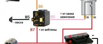
When an electric current passes through the coil, an electromagnetic field is created there, and under its action the armature moves inside the core. When the power is turned off, the field disappears and the armature moves freely in the core. The VAZ 2109 ignition relay consists of an electromagnet, which is wound from an armature, a return spring, contacts and two windings.
The electromagnet consists of two coils: holding and retracting. The retractor is connected to the electric motor contact and the control terminal, and the retainer is connected to the relay body and the control terminal. When voltage is applied to the relay control contact, an electric current flows through the coils, creating an electromagnetic field there, and under its action the armature moves and compresses the return spring.