It is very possible to start a car engine without using an electric starter. To do this, you will either need to push the car well, or ask someone to take you in tow. But, you must admit, there are not always passengers in the cabin with you who would help you start the car from the pusher, and not every driver you meet will agree to carry you.
Unfortunately, problems with engine starting occur everywhere on domestically produced cars. As for the starter, it itself fails quite rarely. But the parts that ensure its operation often fail.
In this article we will talk about what a starter solenoid relay is and understand its design using the VAZ-2114 as an example. In addition, we will consider its malfunctions, as well as possible malfunctions of other elements of the engine starting system that have similar symptoms.
The design of the starting device and where the starter relay is located on the VAZ-2114
The “fourteenth” starter is a conventional DC electric motor, consisting of:
- housings;
- four-pole armature (rotor);
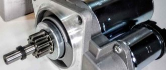
- Bendix (overrunning clutch);
- solenoid (traction) relay.
The device body is closed with two covers. In the design of an electric motor, it plays the role of a stator. Inside it there is a four-pole armature (shaft with windings), rotating around its horizontal axis. The shaft is supported by two support bearings located in the motor housing.
The Bendix, or overrunning clutch, is a mechanism that engages the armature gear with the crankshaft flywheel ring. It is located at the front of the rotor.
Where is the starter relay located on the VAZ-2114? It is located right on it. Above. In fact, this is not an ordinary, in our understanding, device that closes contacts. It performs two functions at once. It closes the contacts of the armature winding and also drives the bendix and gear.
Decoding fuses and relays of block 2114-3722010-18
VAZ-2114, 2115, 2113 cars of the first models with a carburetor have certain differences in the fuse module.
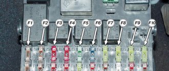
Old style block fuse and relay diagram
Table 2. Decoding of fuses and relays of block 2114-3722010-18
| № | Current, A | Explanation of fuses |
| F9 | 7,5 | Right rear fog lamp |
| F8 | 7,5 | Left rear fog lamp |
| F1 | 10 | Front headlight cleaners at the moment of switching on, wiper contacts, headlight washer switch valve, headlight wiper switch relay contacts |
| F7 | 30 | Front headlight wipers during operation, winding of the relay for turning on the wipers, fuse for the interior heater, windshield washer, gearbox and timing controller for the rear window wiper, valves for turning on the front and rear washer, relay (winding) for turning on the engine cooling system, relay for turning on the rear window heating, glove box lighting, rear window heating control lamp |
| F16 | 15 | Turn signal indicators and activation of hazard warning lights in turn mode, indicator control lamp, reversing lights, gearbox and relay for activation of windshield washers, generator winding (at startup), control lamps for brake fluid, oil pressure, carburetor flap, hand brake. "STOP" display lamp, voltmeter and coolant temperature indicator |
| F3 | 10 | Interior lighting and rear brake light |
| F6 | 30 | Power windows, power windows on/off relay |
| F10 | 7,5 | License plate lights, engine compartment lamp, warning light on the dashboard (exterior lighting), instrument panel lights, cigarette lighter light, heating lever lights |
| F5 | 20 | Relay for turning on the cooling system fan (electric motor), sound signal. |
| F10 | 7,5 | Left front marker light Left rear marker light |
| F11 | 7,5 | Right front headlight, right rear |
| F2 | 10 | Hazard warning lamp, turn signals and hazard warning relay. |
| F4 | 20 | Rear heated glass, heating on, portable socket, cigarette lighter in the cabin |
| F15 | 7,5 | Front right high beam |
| F14 | 7,5 | Front left high beam Light switch |
| F13 | 7,5 | Left low beam |
| F12 | 7,5 | Right low beam |
| № | Relay circuit | |
| K1 | Headlight washers | |
| K2 | Hazard and turn signals | |
| K3 | Windshield wipers | |
| K4 | Monitoring the health of lamps | |
| K5 | Windows | |
| K6 | Sound signal | |
| K7 | Heated rear window | |
| K8 | High beam headlights | |
| K9 | Low beam headlights | |
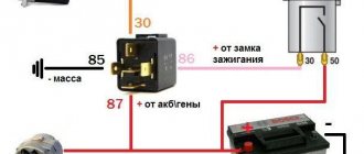
Operating principle
When the ignition is turned off, the armature, thanks to the spring, is in the extended position. The Bendix gear, however, is not engaged with the flywheel crown. When we turn the ignition key to the second position, voltage is applied to the relay contacts. The magnetic field created by the retractor coil drives the armature. It moves backward, compressing the spring, and closes the contacts through which voltage is supplied to the starter. The retracting winding is turned off at this moment, and the holding winding is turned on.
During movement, the armature moves the fork along the rotor shaft. She, in turn, moves the bendix, bringing the gear into engagement with the flywheel. When we release the ignition key, the voltage on the holding coil stops flowing, and the armature returns to its original position under the influence of the spring. The fork, at the same time, disconnects the Bendix gear and the flywheel crown.
Signs of a malfunctioning retractor relay
A faulty traction relay can be identified by the following symptoms:
- when the ignition is turned on, there is no characteristic click accompanying the movement of the device’s armature to the rearmost position (the starter does not turn, the engine does not start);
- a click is heard, but the trigger does not fire;
- The relay is triggered, the starter starts the engine, but does not turn off.
If you turn on the ignition and find that the engine does not start, and one of the listed signs of a faulty starting device is present, try to find the problem yourself. In some cases, the damage may be on the surface, and it will only take a few minutes to fix it.
Electrical diagram of VAZ-2113
General diagram of the electrical equipment of the VAZ 2113 injector (without engine control system).
Click to enlarge diagram
1 – block headlight; 2 – fog lamp; 3 – ambient temperature sensor; 4 – electric motor of the engine cooling system fan; 5 – block for connection to the wiring harness of the engine control system; 6 – engine compartment lamp switch; 7 – spare block for connecting an audio signal with one terminal (the negative terminal is connected to the body); 8 – sound signal; 9 – liquid level sensor in the windshield washer reservoir; 10 – brake pad wear sensor; 11 – low oil level sensor; 12 – generator; 13* – engine compartment lamp; 14 – temperature indicator sensor; 15 – VAZ-2113 starter; 16 – battery; 17 – relay for turning on fog lights; 18 – coolant level sensor in the expansion tank; 19 – sensor of insufficient brake fluid level; 20 – reverse light switch; 21 – windshield wiper gear motor (front windshield wiper); 22 – emergency oil pressure sensor; 23 – rear window washer electric pump; 24 – electric pump for windshield washer; 25 – instrument panel; 26 – mounting block of fuses and relays; 27 – brake signal switch; 28 – ignition relay; 29 – ignition switch (lock); 30 – glove box lighting lamp; 31 – glove box lighting switch; 32 – rear window heating switch; 33 – rear fog light switch; 34 – fog lamp switch; 35 – combined switch for side lights and headlights; 36 – alarm switch; 37 – steering column switches; 38 – brightness control for instrument lighting; 39 – illumination lamp for the headlight hydraulic corrector control handle; 40 – socket for connecting a portable lamp; 41 – side direction indicator; 42 – interior lighting switch (front door open sensor); 43 – interior lamp; 44 – electric fan of the ventilation and heating system; 45 – additional resistor of the electric fan of the ventilation and heating system; 46 – switch for operating modes of the electric fan of the ventilation and heating system; 47 – illumination lamp for the handle of the operating mode switch of the electric fan of the ventilation and heating system; 48 – backlight lamp for the heater control unit; 49 – display unit of the on-board control system; 50 – trip computer; 51 – interior lighting switch (rear door open sensor); 52 – block for connecting a clock; 53 – fuel module; 54 – ashtray illumination lamp; 55 – cigarette lighter; 56 – interior lamp; 57 – switch for the parking brake warning lamp; 58 – rear light 2113; 59 – license plate light; 60 – additional brake light; 61 – heating element for heating the rear window; 62 – rear window wiper gear motor (rear windshield wiper); A – numbers of pins in connecting blocks;
The same diagram, but for convenience, divided into 3 parts:
No clicking of the solenoid relay
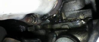
The absence of a click may indicate that either there is no voltage supplied to it, or there are problems with the pull-in winding. First of all, we check the wiring. To do this, visually inspect the positive wire going to the relay from the battery, and then the thin wire from the ignition switch. If possible, check the voltage level with a voltmeter (multimeter), connecting its positive probe to the terminal on the relay from which the wire goes to the battery, and the negative probe to ground. The device should show battery voltage. If this indicator is lower, you need to look for a problem in the wiring.
If there is voltage to the relay, try to start the engine directly, without the ignition switch. To do this, disconnect the wire coming from it and use a screwdriver to close the relay contacts (output to the battery and output to the starter). It worked? Deal with the contact group of the ignition switch.
VAZ-2113 diagram
The VAZ-2113 car was produced in 2004-2013 in the “Norma” and “Lux” configurations. The standard included cars VAZ-21134-20-010 and VAZ-21134-30-010. The luxury ones included VAZ-21134-22-010 and VAZ-21134-32-010; they did not have any special differences compared to the norm, except perhaps the presence of an on-board computer, fog lights and some other minor additions.
Initially, the car was equipped with an eight-valve engine with a volume of 1.6 liters and a power of 79 horsepower. Since 2007, the hatchback began to be equipped with a modernized version of the engine, developing 81 hp. s., and since 2010, a version with a 98-horsepower sixteen-valve engine from Priora has been produced in small series. All cars were equipped with a five-speed gearbox.
The following provides complete and comprehensive information on electrical equipment, including fuse and relay blocks, as well as useful literature on 2113 for independent repair and maintenance, which can be downloaded for free and without registration at the end of the page.
There is a click, but the starter does not turn
If you clearly hear the relay click when you turn on the ignition, the problem is most likely in the starter itself. Perhaps the brushes are worn out, or there is a break in one of the windings. In any case, further diagnostics without dismantling the device is impossible. If a break in the windings is detected, you can try to restore the starting device by entrusting it to winding winding specialists. If things are generally bad with it, it is better to buy a new starter 2114. The price for it varies between 3700-5000 rubles.
Recommendations for care and maintenance
- Buy original fuses. Domestic or foreign, it doesn’t matter;
- Install strictly in accordance with amperage ratings. Unacceptable with lower or higher current strength. In the first case, this will lead to damage to the module, in the second - to breakdown of the unit, which is attached to the fuse;
- Carefully check the quality of fixation of terminals and limit switches on the board. If loose, tighten and press with pliers. A spark can cause a fire and melting occurs;
- If moisture gets in or condensation forms inside the mounting block, remove the cover, dry it, and if necessary, blow it with a stream of compressed air.
Carry out preventive and diagnostic work in the fuse box with the battery terminals removed in order to prevent a short circuit in the circuit.
The average service life of fuses is 40 – 60 thousand km. The service life of foreign analogues is 10–15% longer. Before replacing, read the instructions and get advice from service station specialists.
Sources
- zapchasti.expert/predoxraniteli/predoxraniteli-vaz-2115.html
- vaznetaz.ru/predoxraniteli-i-rele-vaz-2114-2115-2113
- drive2.ru/l/5419303/
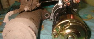
How to replace the VAZ-2114 starter solenoid relay
Now let’s move on to the process of dismantling and replacing the “fourteenth” traction relay. Let us immediately note that for this it is better to remove the starter assembly. This way it will be possible to simultaneously check the condition of its brush assembly and bearings. So, the process of replacing the relay is as follows:
- Remove the negative terminal from the battery.
- Disconnect the wires from the relay terminals and from the terminal of the starter brush assembly.
- Unscrew the bolts securing the starter to the clutch housing. We remove it from its seat.
- Unscrew the coupling bolts securing the relay.
- Disconnect the relay from the starter and install a new one in its place.
- We carry out installation in reverse order.
Main car fuses.
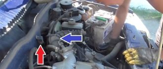
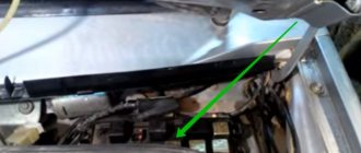
In cars of the fourteenth family there are separate fuses for the fuel pump, as well as the main fuse for the unit, and naturally, like all desktop models, there is a fuse for the main relay. This is also where all these main relays are located, which include the engine control unit and the fuel pump. They are located at the bottom of the instrument panel on the right side of the passenger's feet. In order for you to get to it, you will need to unscrew with a screwdriver the three screws that secure the small cover of the center panel consoles. As an example, you can look at the photo for the location of this panel.
To make it easier for you to check and work with these circuit breakers and relays, it would be better for you to remove this plate completely and remove it from the panel. It is secured with three nuts on the sides; to remove it you will need a small ratchet with an extension and a 10-mm socket.
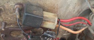
Relay,
No. 1 gas pump,
No. 2 which is the main thing.
No. 3 engine cooling screw,
Diagram of internal connections in the installation room. block of an older version.
Other relay
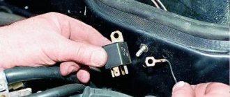
We figured out where the starter relay is located on the VAZ-2114 and how to replace it. But in the engine starting system there is another part with the same name. Yes, yes, it is also called the “starter relay”. Only extra. And its function is completely different. An additional starter relay serves to ensure the safety of the entire starting mechanism. Without it, the brushes and armature windings would burn almost every time it was started.
You will ask again, where is the starter relay located on the VAZ-2114? On the first models of the “fourteenth” it was located in the engine compartment at the top on the partition separating the engine compartment and the interior. On the new VAZ-2114 it is not there. And some “experts” foam at the mouth and prove that cars of the Samara-2 family do not have it at all.
In fact, there is an additional relay, but it is located under the steering column. Just remove the bottom part of the plastic casing and you will immediately see it. This is a regular four-pin relay labeled 98.3777-10 that protects the starter circuit. If you have problems starting the power unit, do not be lazy to check it too.
Interpretation of fuses and relays of injection models
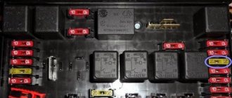
The main electrical fuse module 2114-3722010-60 is located under the front engine compartment. This arrangement allows for quick access to all electrical systems of the car.
Block location
Please note that the location of the electrical fuse module may depend on the type of equipment and year of manufacture of the vehicle. As a rule, this is the upper right part of the engine compartment, under the front windshield. The mounting block is made of plastic in the form of a rectangular box. To protect against accidental opening, the box is equipped with special latches. To open the module, you need to snap off the two protective brackets and lift the top plastic protection. Under the cover are all the main control relays and electrical fuses of the vehicle.
To quickly remove the fuse, special plastic pliers are located on the plastic protection cover. With their help, you can very easily get any element. You need to grab the top edge of the plastic case with pliers and carefully lift the element.
For the convenience of the user, on the top plastic cover there is a complete diagram, made in the form of a schematic image, which shows all the electrical fuses and relays indicating the current strength (A).
Fuse and relay diagram for injection models
Table 1. Explanation of fuses and relays 2114-3722010-60
| № | Current, A | Explanation of fuses |
| F1 | 10 | Rear fog lights, rear fog light indicator lamp |
| F2 | 10 | Turn signals and turn signal breaker relay. Alarm system. Hazard warning lamp |
| F3 | 7,5 | Interior and luggage compartment lighting systems (interior lamp, luggage compartment lamp, ignition key illumination). Brake brake lamp, on-board computer backlight lamp. Engine control lamp |
| F4 | 20 | Rear window heating control. Portable lamp connection socket |
| F5 | 20 | Relay for monitoring and turning on the sound signal. Cooling system engine switch fuse and relay |
| F6 | 30 | Control and relay switching on electric windows |
| F7 | 30 | Electric motor control - heating system, interior heater, windshield washers, headlight cleaners. Interior cigarette lighter, glove box lamp. Turn on the heated rear window. |
| F8 | 7,5 | Turning on the right fog lamp |
| F9 | 7,5 | Turning on the left fog light |
| F10 | 7,5 | Side light for the left side body, indicator light for turning on the side lights (on the display), lamps for illuminating the license plate and engine compartment, illumination lamp for switches, cigarette lighter, heater control levers. Instrument lighting switch. |
| F11 | 7,5 | Right side body marker light |
| F12 | 7,5 | Front right low beam headlight |
| F13 | 7,5 | Front left low beam headlight |
| F14 | 7,5 | Front left high beam headlight. Light indicator lamp. |
| F15 | 7,5 | Front right high beam lamp. |
| F16 | 15 | Body turn signals, relay-breaker for turn signals and hazard warning lights. Control relay and reverse lamps, indicator lamps for the on-board instrument control system, lamps for oil pressure, handbrake activation, brake fluid level, battery charge. On-board computer, engine generator winding. |
| F17-F20 | Spares | |
| № | Relay circuit | |
| K1 | Headlight cleaners | |
| K2 | Turn signals and hazard warning lights | |
| K3 | Windshield wiper | |
| K4 | Monitoring the serviceability of brake light lamps and side lamps | |
| K5 | Window lifters | |
| K6 | Sound signal | |
| K7 | Heated rear window | |
| K8 | High beam headlights | |
| K9 | Low beam headlights | |