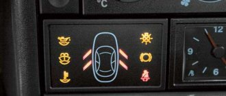
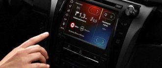
Almost all modern cars are equipped with an on-board unit. This device provides the machine with many useful functions. With its help, you can find out the car’s daily mileage, instantaneous fuel consumption, air temperature, and fuel reserves in the tank. Other functions include additional operating parameters - air flow, crankshaft and damper position, and other data.
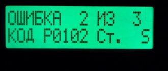
However, the most useful function of an on-board or trip computer is the provision of error information. The device can find out the error number that occurs during engine operation and display it on the screen without additional diagnostics. This allows you to troubleshoot problems without having to pay for diagnostics or unexpected repairs.
Some car models released from the factory do not have this useful device, which makes servicing the car difficult. Therefore, owners strive to carry out their own tuning of vases. Installing an on-board computer on a VAZ 2110 with your own hands will not pose any special problems. If connected correctly, operating time will not take more than an hour. The article will show you how to install and configure the device on a VAZ 2110-2111, and will also tell you about the models and prices of on-board computers.
Types of bookmakers
On-board devices are divided into several types. Injection or carburetor devices are suitable for the VAZ 2110, depending on the type of power system for the car. Additionally, devices are divided into stationary, installed only in specially designated places, or universal, of any size, which can be placed in any convenient place.
Among other things, there are devices that are suitable only for one model. For example, VAZ 20199, but it does not work on VAZ 2110. This may cause the device to display data incorrectly. It’s worth remembering this when purchasing and purchasing an on-board computer that can be installed specifically on these models.
The most common and convenient devices for the VAZ 2110 are simple State 110-X5 devices, the price of which starts from 2-3 thousand rubles. The bortovik is compatible with the old panel and has a number of simple functions, such as information on fuel consumption, coolant temperature in the tank, estimated power reserve and mileage until the upcoming maintenance, coupled with decoding engine errors.
It is best to give preference to more expensive devices such as Omega 168, Orion or Mutltronics. Such devices have an expanded range of useful functions that will significantly simplify the operation of the car. And you won’t be scared by how much such an on-board computer costs. The maximum cost of advanced BCs, which come with a dashboard that simplifies installation, reaches 10-12 thousand rubles.
Connection diagram
The process of diagnosing an ECU using a special scanner.
Electronic control units of the VAZ-2110 are the main tool for controlling and automating most processes in the car. To adjust the software, they often resort to replacing the “brains” with more “flexible” ones and reflashing the ECU.
First of all, it is necessary to clarify several terms that will be required when considering questions about changing the electronic control unit:
- Wiring compatibility . To replace it, the connectors on the old ECU and the new one will need to match.
- Software is a predetermined algorithm that can change depending on the needs or desires of the motorist.
- The hardware component is the electronic control unit itself, boards or other components that allow the systems associated with the ECU to function normally.
For the VAZ-2110 family there were two types of connectors. So, for the “brains” January 5.1.x, Bosch M1.5.4, Bosch MP7.0, and VS 5.1 there was a 51-pin connector, but for January 7.2(+), Bosch M7.9.7(+) and M73 - 81 -pin.
That is, the interchangeability of control units is caused by the pinout of the unit.
ECU January 7.2.
Differences
Fundamental differences between 81-pin blocks and blocks of previous generations:
- Overall body dimensions and weight have been reduced.
- New, more modern connectors with improved connection reliability.
- The controllers have built-in switches, therefore, instead of ignition modules, ignition coils can be used, which increase the reliability of the ECM as a whole.
- There is no software or hardware compatibility with any of the previously released units.
Even electronic control units from the same manufacturer will differ significantly in pinout. Therefore, the interchangeability of the “brains” will depend on the number of connector pins. Also, it is worth understanding that the firmware will play a big role. When changing the ECU, the motorist will have to reflash the unit for the correct operation of all vehicle devices.
ECU January 5.1.
A very important nuance remains that the software of the control unit must be compatible and comply with the type of injection, as well as the toxic standards laid down by the manufacturer.
Assignment of contacts of ECU Bosch M1.5.4, MP7.0 and January-5.1
Pinout of 55-pin ECU.
Let's look at the pinout of control units with 55-pin “brains”:
| Bosch M1.5.4 (1411020 and 1411020-70) January 5.1.1 (71) | Bosch M1.5.4 (40/60) January-5.1 (41/61) January 5.1.2 (71) | Bosch MP7.0 | |
| 1 | Ignition 1-4 cylinders. | Ignition 1-4 cylinders. | Ignition 1-4 cylinders. |
| 2 | . | Ground ignition wire. | . |
| 3 | Fuel pump relay | Fuel pump relay | Fuel pump relay |
| 4 | Stepper motor PXX(A) | Stepper motor PXX(A) | Stepper motor PXX(A) |
| 5 | Canister purge valve. | Canister purge valve. | |
| 6 | Cooling fan relay | Cooling fan relay | Left fan relay (only on Nivas) |
| 7 | Air flow sensor input signal | Air flow sensor input signal | Air flow sensor input signal |
| 8 | . | Phase sensor input signal | Phase sensor input signal |
| 9 | Speed sensor | Speed sensor | Speed sensor |
| 10 | . | General. Oxygen sensor weight | Oxygen sensor weight |
| 11 | Knock sensor | Knock sensor | Knock sensor input 1 |
| 12 | Power supply for sensors. +5 | Power supply for sensors. +5 | Power supply for sensors. +5 |
| 13 | L-line | L-line | L-line |
| 14 | Weight of injectors | Weight of injectors | Weight of injectors. Power "ground" |
| 15 | Control of injectors 1-4 | Oxygen sensor heater | Check Engine Light |
| 16 | . | Injector 2 | Injector 3 |
| 17 | . | Recirculation valve | Injector 1 |
| 18 | Power supply +12V non-switchable | Power supply +12V non-switchable | Power supply +12V non-switchable |
| 19 | Common wire. Weight of electronics | Common wire. Weight of electronics | Common wire. Weight of electronics |
| 20 | Ignition 2-3 cylinders | Ignition 2-3 cylinders | |
| 21 | Stepper motor PXX© | Stepper motor PXX© | Ignition 2-3 cylinders |
| 22 | Check Engine Light | Check Engine Light | Stepper motor PXX(B) |
| 23 | . | Injector 1 | Air conditioner relay |
| 24 | Stepper motor weight | Weight of stepper motor output stages | Power grounding |
| 25 | Air conditioner relay | Air conditioner relay | . |
| 26 | Stepper motor PXX(B) | Stepper motor PXX(B) | Weight of sensors TPS, DTOZH, DMR |
| 27 | Ignition switch terminal 15 | Ignition switch terminal 15 | Ignition switch terminal 15 |
| 28 | . | Oxygen sensor input | Oxygen sensor input |
| 29 | Stepper motor PXX(D) | Stepper motor PXX(D) | Oxygen sensor 2 input signal |
| 30 | Weight of sensors MAF, DTOZH, DPS, DD, DPKV | Weight of sensors MAF, DTOZH, DPS, DD, DPKV | Knock sensor input 2 |
| 31 | . | Reserve output high current | Rough road sensor input signal |
| 32 | . | . | Fuel consumption signal |
| 33 | Control of injectors 2-3 | Oxygen sensor heater. | . |
| 34 | . | Injector 4 | Injector 4 |
| 35 | . | Injector 3 | Injector 2 |
| 36 | . | Exit. Intake pipe length control valve. | Main relay |
| 37 | Nutrition. +12V after the main relay | Nutrition. +12V after the main relay | Nutrition. +12V after the main relay |
| 38 | . | Low-current backup output | . |
| 39 | . | . | Stepper motor РХХ © |
| 40 | . | Reserve input discrete high | . |
| 41 | Request to turn on the air conditioner | Request to turn on the air conditioner | Oxygen sensor heater 2 |
| 42 | . | Reserve input discrete low | . |
| 43 | Signal to tachometer | Signal to tachometer | Signal to tachometer |
| 44 | CO - potentiometer | Air temperature sensor | . |
| 45 | Coolant temperature sensor | Coolant temperature sensor | Coolant temperature sensor |
| 46 | Main relay | Main relay | Cooling fan relay |
| 47 | Programming permission | Programming permission | Air conditioner request signal input |
| 48 | Crankshaft position sensor. Low level | Crankshaft position sensor. Low level | Crankshaft position sensor. Low level |
| 49 | Crankshaft position sensor.High level | Crankshaft position sensor.High level | Crankshaft position sensor.High level |
| 50 | . | Recirculation valve position sensor | Programming permission |
| 51 | . | Request to turn on the power steering | DC heater |
| 52 | . | Reserve input discrete low | . |
| 53 | Throttle position sensor | Throttle position sensor | Throttle position sensor |
| 54 | Fuel consumption signal | Fuel consumption signal | Stepper motor IAC (D) |
| 55 | K-line | K-line | K-line |
We recommend: Arranging the exterior of your car
Description of contacts ECU M7.9.7 / January 7.2
Let's look at the pinout of control units with 81-pin “brains”:
| № | Compound |
| 1 | 21114 - Not used / 21124 - Ignition coil 2 cylinders. |
| 2 | 21114 - Ignition 2-3. Control of the primary winding of the ignition coil, act. level is low. / 21124 — Ignition coil 3 cylinders. |
| 3 | Ignition circuit weight |
| 4 | 21114 - Not used / 21124 - Ignition coil 4 cylinders. |
| 5 | 21114 - Ignition 1-4. Control of the primary winding of the ignition coil, act. level is low. / 21124 - Ignition coil of cylinder 1. |
| 6 | Injector 2. Active level low |
| 7 | Injector 3. Active level low |
| 8 | Output to tachometer. |
| 9 | Not used |
| 10 | Fuel consumption signal |
| 11 | Not used |
| 12 | Battery, terminal 30 of the ignition switch. |
| 13 | Nutrition. Ignition switch terminal 15 |
| 14 | Main relay |
| 15 | Contact "A" DPKV |
| 16 | TPDZ |
| 17 | TPS mass / TPS mass, DND |
| 18 | Input - oxygen sensor |
| 19 | Input - knock sensor |
| 20 | Knock sensor weight |
| 21 | Not used |
| 22 | Not used |
| 23 | Not used |
| 24 | Not used |
| 25 | Bosch Only - High Current Output, Reserved |
| 26 | Bosch Only - High Current Output, Reserved |
| 27 | Injector 1. Active level low |
| 28 | Not used / DK2 heater control output |
| 29 | Not used / Engine cooling fan control output 2 |
| 30 | Not used |
| 31 | CE lamp, act. level low |
| 32 | Power supply TPDZ / Power supply TPDZ, DND |
| 33 | Power supply for mass air flow sensor |
| 34 | DPKV input, contact “B” |
| 35 | Weight of DTOZH / Weight of DTOZH, mass air flow sensor, 1 DC (UDK), 2 DC (DDK) |
| 36 | Mass of the mass air flow sensor |
| 37 | Signal input from mass air flow sensor |
| 38 | Not used |
| 39 | Signal input from DTOZH |
| 40 | Signal input from intake air temperature sensor |
| 41 | Not used |
| 42 | Not used / DND signal input |
| 43 | Not used |
| 44 | On-board voltage input at the main relay output |
| 45 | Phase sensor power output |
| 46 | Canister purge valve control output |
| 47 | Injector 4. Active level low |
| 48 | Oxygen sensor heater control output |
| 49 | Not used |
| 50 | Additional starter relay control output |
| 51 | Controller weight |
| 52 | Not used |
| 53 | Controller weight |
| 54 | Not used |
| 55 | Not used / Signal input DK2 (DDK) |
| 56 | Not used |
| 57 | Input for encoding calibration data options. The controller memory can contain 2 sets of calibration data; switching is performed by shorting to ground. |
| 58 | Not used |
| 59 | Speed sensor |
| 60 | Not used |
| 61 | Weight of output stages |
| 62 | Not used |
| 63 | On-board voltage input at the main relay output |
| 64 | Output “D” IAC |
| 65 | Output “C” IAC |
| 66 | Output “B” IAC |
| 67 | Output “A” IAC |
| 68 | Engine cooling fan relay control output, act. level - low |
| 69 | Air conditioner relay control output, act. level - low |
| 70 | Fuel pump relay control output, act. level - low |
| 71 | K-Line |
| 72 | Not used |
| 73 | Not used |
| 74 | Not used |
| 75 | Input request to turn on the air conditioner, act. level - high |
| 76 | Power steering request input, act. level - high |
| 77 | Not used |
| 78 | Not used |
| 79 | Phase sensor signal input |
| 80 | Weight of output stages |
| 81 | Not used |
The main differences between a BC injector and a carburetor
The main differences between the bk, depending on the type of power supply, are the on-board capabilities for the VAZ 2110. The carburetor type is the simplest. The main reason is that carburetors are largely controlled mechanically, and electronics play a secondary role. Therefore, its standard set of functions is extremely small. You can find out about:
- time of day or set an alarm;
- current and average fuel consumption, as well as power reserve;
- average speed and driving mode;
- engine or outside air temperature;
- diagnostic information that allows you to find out about an engine operation error and decode it.
Lada 2112 Hooliganka › Logbook › -Installation of on-board computer STATE 110x5-m;
Good health to everyone!
As was written earlier in the B/F, I planned to purchase an on-board computer at a reasonable price for me, ranging from 1500 to 2500 rubles.
THANKS TO ALL THOSE WHO LEFT THEIR FEEDBACK AND RECOMMENDED THIS OR ANOTHER ON-BOARD COMPUTER! .Having searched for on-board computers in my city, as it turned out, the choice was small, and then a day later a friend called me from another city and found me on-board computers at a reasonable price and what I needed, initially there were several models to choose from,
STATE 110x4-m
,
STATE 110x5-m
and
ORION BK-30-40
..., but after looking at the reviews and characteristics I chose the
STATE 110x5-m.
Just the day before yesterday, my friend Garamaj safely delivered it to me, for which I want to express my deep gratitude to him! .
Immediately after assembling the car interior, I decided to connect the BC, as it turned out there is nothing complicated, the only thing is that there is still no access to the engine temperature, car speed, revolutions, etc. “it says that there is no connection with the controller,” what could it be?
.
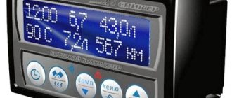
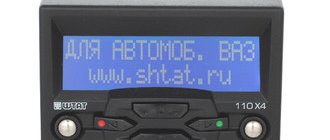
and so everything works Description from the manufacturer BC STATE 110x5-M:
On-board computer STATE 110X5-M.
The trip computer State 110X5-M is designed for installation on fuel-injected cars VAZ 2110, VAZ 2111, VAZ 2112 with any panel. The new design significantly improves its user characteristics. Characteristics
Voice accompaniment: Yes Installation location: In a standard place Display type: LCD monochrome Taximeter: Yes Item name: On-board computer Brand: State Model: 110×5-M
Disadvantages of the BC injector
Some VAZ 2110 models are equipped with a standard on-board computer. This model has a certain number of disadvantages and limitations. For example, the model interacts poorly with the electronic control unit (ECU) and does not allow receiving data through a special diagnostic connector. However, only motorists with on-board computers in the state face this problem. In addition, this can be treated with a standard flashing of factory settings.
If the BC is installed separately on the VAZ 2110, then it can be easily customized for yourself. If connected correctly, the device will not cause problems. If there are still difficulties, for example, the Check light comes on, but the diagnostics shows that such an error code does not exist.
This means that the contacts of the on-board computer may come loose or the electronic system may fail. You need to restart the bookmaker or turn it off for a few minutes. Next, we reconnect and configure the device according to the operating instructions.
- some models of on-board aircraft do not allow reading errors;
- incorrect connection of the computer to the VAZ 2110 can cause errors in the ignition system;
- shows incorrect fuel consumption values due to a faulty mass air flow sensor.
Advantages of injection engines
The engine designs are the same, only the following systems differ significantly:
- Fuel mixture injection.
- Ignition.
- Engine control.
The main advantages of injection engines:
- If faults occur, diagnostic tools will provide an accurate diagnosis in a matter of minutes. In rare cases, it becomes necessary to take the car to a service center for servicing.
- Ideal operation at idle speed, provided that all sensors function stably. Starting the engine in winter is much easier.
- Fuel consumption (depending on the firmware, however) is significantly less than that of carburetor engines.
- Injection systems require virtually no intervention. Sensors and actuators rarely fail.
The cost of spare parts is significantly higher than for carburetor engines. But they also break less often. If the injector is new or has just been serviced, then with proper use it will last for more than one year without breakdowns. If the sensors break down, they can be replaced within a few minutes. And some devices can be repaired.
Rules for driving a car with an injector
A car equipped with an injector is less susceptible to ambient temperatures. However, in severe frost, the injection Lada also experiences difficulty starting. Here it is worth using the on-board computer with the function of heating spark plugs. Every time the temperature drops below a certain value and the car is turned off, a special heating of the tips is carried out to ensure a stable engine start.
Also, the VAZ engine sometimes overheats, which can cause valve burnout and costly overhauls. However, this is possible if the cooling system is faulty. If necessary, you can activate the Tropic function for the on-board computer of the VAZ 2110. When the temperature reaches more than the value set by the owner, the forced cooling fan turns on.
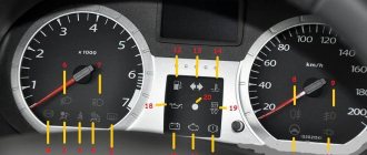
How to connect the State on-board computer to a VAZ 2110 (instructions)
With the advent of more modern technologies, domestic cars began to be equipped with on-board computers. The VAZ 2110 model was no exception.
Thanks to the on-board computer on the VAZ 2110, you can check for yourself what condition the car is in, what problems have arisen and how to solve them.
Installation of BC for injector
Connecting the on-board computer is quite simple. The VAZ 2110 offers several models - a standard one, which takes the place of a standard clock, or universal ones, which can be positioned at your discretion.
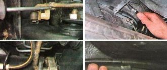
- You need to find a standard connector for connection. Remove the trim from the VAZ 2110 at the bottom of the torpedoes, as a rule, it is located there.
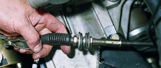
- Next, you should find the K-line wire and connect it to the car's ECU. The location of the wire is indicated on the on-board computer connection diagram (see photo).
- You can connect an air temperature sensor (it is better to install it in the rear bumper or near the steering tips), fuel consumption or car speed to separate connectors. The pinout of the block is shown above.
If necessary, you can install an on-board computer in addition to the standard one. This will save space on the panel. For example, a Sigma or Staff computer is installed on a VAZ 2112 instead of the standard plug for the SAUO unit and there is no need to wire the contacts. It is necessary to connect three contacts - 12 volt, K-line and ground.
Electrical connections
During the preparation stage, you must perform the following steps:
- Disconnect the negative terminal from the battery.
- The VAZ-2110 on-board computer is connected to the alarm block. Find it and position it as conveniently as possible.
- You will need to first locate the orange wire (at pin seven).
- Connect the red-white wire to it, which is located in the computer connection harness.
- To the red-black wire installed in the tenth pin, connect the red one from the harness coming from the trip computer.
- And connect the red on the block with the red-black coming from the BC harness.
- Find the black wire on the fifth pin. And you connect the same one from BC to it.
- A white wire is installed on the eighth contact, which you connect to a similar one going to the BC.
User manual
Additionally, it is worth setting up the computer for the VAZ 2110 after all devices have been installed. The device, as a rule, has a special cross. These buttons help you configure the device. For example, to connect a fuel level sensor, you need to drain the tank, turn on the device, and press the diagnostic button.
The device will carry out the analysis, and then a numerical designation will appear on the display. This amount of gasoline should be poured. The computer will then move on to another phase of analysis. Once completed, you can fill the tank full. The full set of settings is indicated in the operating manual for a specific device and you can make a choice in favor of the desired functions.
conclusions
Determining the compatibility of the electronic engine control unit is quite simple; to do this, you should look at the pinout of the connectors, and also read the technical specifications. You can replace the “brains” yourself.
Sources
- https://MasteraVaza.ru/salon/bortovoj-kompyuter/kolodka-bortovogo-kompyutera-vaz-2110-583
- https://FB.ru/article/342090/bortovyie-kompyuteryi-na-vaz—podklyuchenie-bortovogo-kompyutera-vaz—instruktsiya
- https://carfrance.ru/zamena-bortovoj-kompyuter-vaz-2110/
- https://DaciaClubmd.ru/repair/elektrika/bortovoj-kompyuter-vaz-2110
- https://luxvaz.ru/vaz-2110/17-podklyuchnie-bortovogo-kompyutera.html
Correct operation
With the right approach, the installed BC will not cause problems. However, if it shows unreliable information, then it is worth removing the on-board computer and checking it for serviceability. How to remove the device is clear. After all, it has a disconnectable connector, so you need to dismantle it in the reverse order. The main thing to remember is that this is a fragile thing and can be broken.
After dismantling, you should check the integrity of the soldering and wires and eliminate any breaks . Afterwards, put the device where it was before and use the working device again.
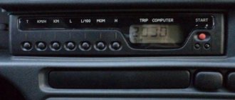
Trip computer
Trip computer (MC), shown in Fig. 37, is installed in a variant version instead of a clock in VAZ 2110, VAZ 2111, VAZ 2112 cars. The MK has 15 functions, divided into 3 groups (see Table 2). The group is selected using buttons 1, 2 and 3.
In each group, functions are divided into basic and additional. The main functions are navigated through the ring using buttons 1, 2 and 3. Additional functions are navigated through button 5. When the ignition is turned off, the computer is always in the “Current Time” mode. When the battery is removed, the clock progress and all accumulated parameters are retained for at least 1 month.
Choice of "Brains"
AvtoVAZ Lada 2110 cars have been equipped with several electronic control units throughout their production history. Thus, the following ECUs can be found on vehicles:
- January 4 - the cost of such an electronic control unit is 4,000 rubles.
- Bosch M1.5.4 - the average price will be 5,500 rubles.
- January 5.1 - the market price will be about 6,000 rubles.
- VS 5.1 - cost 5,000 rubles.
- Bosch MP7.0 - the cost of the control unit will be around 6,000 rubles.
- Bosch M7.9.7 is a little more expensive than its brother, the price ranges from 6000-6500 rubles.
- January 7.2 and January 7.2+ - these blocks will cost the car owner 5000-5500 rubles.
According to the experience of motorists and the recommendations of specialists, it is best to take electronic control units marked Bosch MP7.0, January 7.2+ and January 5.1.
If you have to change the remaining blocks, it is recommended to take an ECU with these markings, since they are more “flexible” for changing the software.
ADJUSTING THE COMPUTER FUNCTION
Clock correction
Press button 4 in the “Current time” mode. At the sixth signal of the exact time, press button 1, this resets the seconds and rounds the clock readings.
Setting the current time (calendar)
Setting an alarm
- Press button 4 in Alarm mode.
- Use buttons 5, 6 to set the desired hour value.
- Press button 4. Use buttons 5, 6 to set the desired minute value.
- Press button 4 to complete the alarm setting.
- In the “Current time” mode, the alarm symbol will light up (the alarm is on).
* If the counter of any of the accumulated parameters (“Travel time”, “Travel time with stops”, “Total consumption”, “Trip mileage”) overflows, all accumulated ones, as well as calculated ones (“Average fuel consumption”, “Forecast”) are reset mileage on remaining fuel", "Average speed") parameters, with the appearance of a two-tone sound signal.
Turning off the alarm
- Press button 4 in Alarm mode.
- Press button 1 to turn off the alarm. “—.—” will appear in the digital digits, and in the “Current time” mode the alarm symbol will not light up (the alarm is turned off).