Some car owners ask search engines where the VAZ 2114 starter fuse is located, but they do not find an answer, because the VAZ 2114 and earlier models of cars from this manufacturer do not have a starter fuse. On several sites, in response to requests for the location of the fuse, huge reviews have been written about the mounting block, but they also do not essentially answer the question posed, because there is no fuse in the mounting block .
The protective function is assigned to the auxiliary relay - a compact device that is located under the steering wheel next to the hood release handle.
VAZ 2115 starter relay where is it located
Today, every car, regardless of type, is equipped with special protection for all electrical systems. This protection is called a fuse. They are installed so that in the event of a short circuit or malfunction, the system can turn off via a fuse, thereby protecting itself from breakdown. Fuses are used for every electrical circuit, from a small light bulb to an engine's ignition system. More important engine systems are equipped with special relays, they protect various pumps, electric motors and other powerful sources of electricity consumption.
The fuse is a small structure consisting of a plastic casing with a fusible element inside. If a short circuit occurs, the thin contact melts under the influence of current, which interrupts the electric current. The simplest electrical fuse is a thin copper wire inserted into a circuit. If the upper limit of the supplied current increases, the contact begins to melt and interrupts the flow of electricity. Here there is a description of all fuses and relays for VAZ 2113, 2114, 2115 models of injection and carburetor types, old and new models.
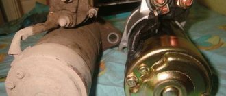
Dismantling and replacement
To make it more convenient to replace the relay, it is recommended not to be lazy and still remove the starter itself. This will allow you to simultaneously check the condition of the starter while replacing the relay.
First, disconnect the negative terminal from the battery. Otherwise, you will be seriously shocked. There is little pleasure in this. Plus, this will lead to burnout of the wiring, which will be extremely difficult and time consuming to change.
The removal procedure described below concerns an assembled relay, which has the ability to replace individual structural elements.
- Disconnect the negative terminal from the battery.
- Disconnect the red terminal from the relay. This is a red wire.
- Using an 8 mm wrench, unscrew the nut securing the brush assembly. You will find it behind the relay.
- Remove the contact that this nut held in place.
- Unscrew the fastening of the solenoid relay to ground. We are talking about coupling bolts.
- Next, you need to dismantle the power wire, after which the relay itself is pulled out.
- The fastening nuts are unscrewed from the end part, which allows you to remove the upper part of the relay.
- It is advisable to immediately replace the relay core with a new one.
- Install a new relay.
- Proceeding strictly in reverse order, reassemble the assembly, which will allow you to complete the replacement of the unit.
- When separating the relay into its two component parts, be sure to ensure that the core does not slip out and the spring does not jump out.
We can say that replacing the gearbox on a VAZ 2114 is not so difficult. It is much easier to replace a non-separable relay, since to replace it it is enough to unscrew all the fasteners in the same way and disconnect the contacts.
Interpretation of fuses and relays of injection models
The main electrical fuse module 2114-3722010-60 is located under the front engine compartment. This arrangement allows for quick access to all electrical systems of the car.
Block location
Please note that the location of the electrical fuse module may depend on the type of equipment and year of manufacture of the vehicle. As a rule, this is the upper right part of the engine compartment, under the front windshield. The mounting block is made of plastic in the form of a rectangular box. To protect against accidental opening, the box is equipped with special latches. To open the module, you need to snap off the two protective brackets and lift the top plastic protection. Under the cover are all the main control relays and electrical fuses of the vehicle.
To quickly remove the fuse, special plastic pliers are located on the plastic protection cover. With their help, you can very easily get any element. You need to grab the top edge of the plastic case with pliers and carefully lift the element.
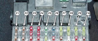
For the convenience of the user, on the top plastic cover there is a complete diagram, made in the form of a schematic image, which shows all the electrical fuses and relays indicating the current strength (A).
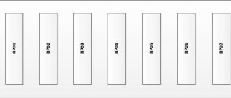
Fuse and relay diagram for injection models
Table 1. Explanation of fuses and relays 2114-3722010-60
| № | Current, A | Explanation of fuses |
| F1 | 10 | Rear fog lights, rear fog light indicator lamp |
| F2 | 10 | Turn signals and turn signal breaker relay. Alarm system. Hazard warning lamp |
| F3 | 7,5 | Interior and luggage compartment lighting systems (interior lamp, luggage compartment lamp, ignition key illumination). Brake brake lamp, on-board computer backlight lamp. Engine control lamp |
| F4 | 20 | Rear window heating control. Portable lamp connection socket |
| F5 | 20 | Relay for monitoring and turning on the sound signal. Cooling system engine switch fuse and relay |
| F6 | 30 | Control and relay switching on electric windows |
| F7 | 30 | Electric motor control - heating system, interior heater, windshield washers, headlight cleaners. Interior cigarette lighter, glove box lamp. Turn on the heated rear window. |
| F8 | 7,5 | Turning on the right fog lamp |
| F9 | 7,5 | Turning on the left fog light |
| F10 | 7,5 | Side light for the left side body, indicator light for turning on the side lights (on the display), lamps for illuminating the license plate and engine compartment, illumination lamp for switches, cigarette lighter, heater control levers. Instrument lighting switch. |
| F11 | 7,5 | Right side body marker light |
| F12 | 7,5 | Front right low beam headlight |
| F13 | 7,5 | Front left low beam headlight |
| F14 | 7,5 | Front left high beam headlight. Light indicator lamp. |
| F15 | 7,5 | Front right high beam lamp. |
| F16 | 15 | Body turn signals, relay-breaker for turn signals and hazard warning lights. Control relay and reverse lamps, indicator lamps for the on-board instrument control system, lamps for oil pressure, handbrake activation, brake fluid level, battery charge. On-board computer, engine generator winding. |
| F17-F20 | Spares | |
| № | Relay circuit | |
| K1 | Headlight cleaners | |
| K2 | Turn signals and hazard warning lights | |
| K3 | Windshield wiper | |
| K4 | Monitoring the serviceability of brake light lamps and side lamps | |
| K5 | Window lifters | |
| K6 | Sound signal | |
| K7 | Heated rear window | |
| K8 | High beam headlights | |
| K9 | Low beam headlights | |
Checking work
Sometimes, despite more than obvious signs of breakage or wear of the retractor, in reality everything turns out to be wrong. The car may behave similarly with some other malfunctions.
Therefore, in order to figure out whether the relay works or not, and also who is the real culprit for the violation of the functionality of the system, we will conduct several checks.
- Check the starter. Turn the ignition key. The starter should begin to turn, and the relay should make a characteristic click. If the starter is not doing its job, replace it. Relyukha has nothing to do with it in this case.
- Check the solenoid relay. To do this, there are two copper bolts on the back cover. Two contacts are attached to them. If the starter starts turning, then your relay has definitely failed and needs to be replaced. In this case, you should not remove the starter, which will allow you to get more accurate test results.
- If you have removed the starter, the check is performed slightly differently : Connect the contact wire of the retractor relay to the positive terminal of the battery;
- The second contact connects the starter ground and the battery charger;
- When the contacts are placed on the relay terminals, the relay should turn on with a characteristic click;
- If the operation is too slow, uncharacteristic, check the condition of the contacts. They often burn out or oxidize.
Decoding fuses and relays of block 2114-3722010-18
VAZ-2114, 2115, 2113 cars of the first models with a carburetor have certain differences in the fuse module.
Old style block fuse and relay diagram
Table 2. Decoding of fuses and relays of block 2114-3722010-18
| № | Current, A | Explanation of fuses |
| F9 | 7,5 | Right rear fog lamp |
| F8 | 7,5 | Left rear fog lamp |
| F1 | 10 | Front headlight cleaners at the moment of switching on, wiper contacts, headlight washer switch valve, headlight wiper switch relay contacts |
| F7 | 30 | Front headlight wipers during operation, winding of the relay for turning on the wipers, fuse for the interior heater, windshield washer, gearbox and timing controller for the rear window wiper, valves for turning on the front and rear washer, relay (winding) for turning on the engine cooling system, relay for turning on the rear window heating, glove box lighting, rear window heating control lamp |
| F16 | 15 | Turn signal indicators and activation of hazard warning lights in turn mode, indicator control lamp, reversing lights, gearbox and relay for activation of windshield washers, generator winding (at startup), control lamps for brake fluid, oil pressure, carburetor flap, hand brake. "STOP" display lamp, voltmeter and coolant temperature indicator |
| F3 | 10 | Interior lighting and rear brake light |
| F6 | 30 | Power windows, power windows on/off relay |
| F10 | 7,5 | License plate lights, engine compartment lamp, warning light on the dashboard (exterior lighting), instrument panel lights, cigarette lighter light, heating lever lights |
| F5 | 20 | Relay for turning on the cooling system fan (electric motor), sound signal. |
| F10 | 7,5 | Left front marker light Left rear marker light |
| F11 | 7,5 | Right front headlight, right rear headlight |
| F2 | 10 | Hazard warning lamp, turn signals and hazard warning relay. |
| F4 | 20 | Rear heated glass, heating on, portable socket, cigarette lighter in the cabin |
| F15 | 7,5 | Front right high beam |
| F14 | 7,5 | Front left high beam Light switch |
| F13 | 7,5 | Left low beam |
| F12 | 7,5 | Right low beam |
| № | Relay circuit | |
| K1 | Headlight washers | |
| K2 | Hazard and turn signals | |
| K3 | Windshield wipers | |
| K4 | Monitoring the health of lamps | |
| K5 | Windows | |
| K6 | Sound signal | |
| K7 | Heated rear window | |
| K8 | High beam headlights | |
| K9 | Low beam headlights | |
Replacing fuses on a VAZ 2114
When any problems are detected in the operation of the car’s electrical network and engine, be it the burnout of light bulbs or the failure of some electrical devices, the driver must first check the functionality of the fuses. The procedure is as follows:
- determine where the fuses are located on the VAZ 2114, which may have failed. To do this, look in the machine’s operating manual for a diagram of the location of the protective devices and determine whether they are located in the mounting block or under the dashboard in the area where the front passenger’s feet are located;
- when working with the car's electrical system, the negative contact of the battery must be disconnected;
- open the plastic latches holding the mounting block cover;
- remove the plastic tweezers from the mount in the upper right part of the block; they can be red, transparent or yellow;
- take the protective device, the circuit of which is supposed to be broken, by the body with tweezers and pull out the fuse;
- There are rules, developed by operating experience, on how to check the fuse. First of all, it is necessary to visually determine whether the fuse-link inside the case has burned out or whether the charger is in good condition;
- if the destruction of the insert cannot be visually determined, it is necessary to check the protective device using a device;
- If confirmation is received that the fuse has blown, it must be replaced with a functional one. The price for a VAZ 2114 fuse box on the automotive market is about 2,000 rubles, and a set of separate chargers of this type will cost 150 -250 rubles.
It is strictly forbidden to install home-made devices or jumpers in place of failed chargers, as well as fuses with a different rated insert current. A short circuit or fire may occur.
When working with the mounting block, do not use metal screwdrivers or other metal tools, this can lead to a short circuit and failure of the mounting tracks of the block.
This is interesting: The scooter does not develop speed
We invite you to watch this useful video:
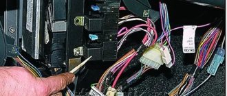
Starter, ignition, rear fog lamp relay
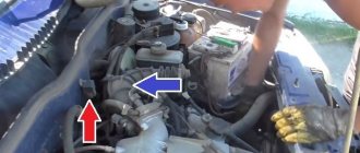
In order to carry out quick checks and repairs, the ignition system relay is installed under the front dashboard of the car, behind the hood release handle. It is located just below the central dashboard. The module is closed with a plastic plug, which must be opened slightly to test for functionality.
Starter, ignition, rear fog lamp relay
Next to the indicated relay, there is a similar one for the rear fog lights and the starter.
The main task of the relay when igniting is to reduce the applied load to the contacts. When the engine starts, the relay turns off some electrical circuits in the vehicle system. The system is used not only in injection, but also in carburetor engines.
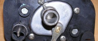
In the event of a malfunction or malfunction in the ignition system, it is necessary to monitor the operation of the relay. For this purpose, open the box and carefully remove the desired element. It is attached using contacts to special grooves. The first thing to do is look at the oxidation of the contacts, if necessary, clean them with a soft cloth or treat them with a special liquid.
To check functionality, you need to use a regular multimeter. We connect to incoming connections and check the numbers. If there is no short circuit when current is applied, it means the element is not working. Replacement is carried out in a similar manner. It is necessary to use a standard element with the number of amperes indicated on the housing.
Starter wiring diagram
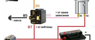
To understand the electrical part of the starter, let’s first get acquainted with its circuit and try to figure out how it works, what elements it consists of, what task the individual elements of the circuit perform.
Useful : Replacing the VAZ 2114 starter (step by step instructions)
The driver inserts the key into the ignition switch (6) and turns the key to start the process. Electric current from the battery (2) is sent to the generator (3) and to the solenoid relay mounted on the starter (1). When the generator is running, it begins to generate electricity and directs it to the tires of the mounting block (4), from where the current flows to the auxiliary starter relay and ignition switch. The relay closes the circuit and directs current to the coil of the solenoid relay, which in turn causes the starter to rotate using bendix. And he starts the engine.
Front fog lamp relay
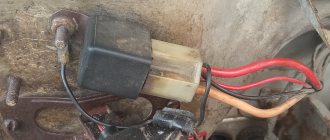
Front fog lights are not standard equipment on the model and are equipped depending on the configuration. The relay itself (if there are fog lights) is located in the engine compartment on the left mudguard.
Front fog lamp relay
Important! To access the relay, you must remove the battery! Without performing this manipulation, it will be difficult to remove and check its functionality.
Replacing a faulty element is very simple. You need to take a Phillips screwdriver (with a short handle), unscrew the bolt securing the relay to the car body, and check the element for malfunction. If it fails, we buy a new one and put everything in the reverse order.
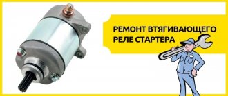
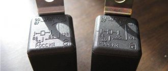
Malfunctions and their symptoms
If you visually inspect the relay when it malfunctions, you may notice stuck contacts, traces of charring on the wiring, burnt windings, and signs of wear.
But it is not at all necessary to disassemble the assembly to recognize the signs of a faulty solenoid relay. They look like this:
- The engine runs, but the starter still turns. At the same time, the sound is too loud and uncharacteristic;
- When the ignition is turned on, the starter does not spin, although the relay makes a characteristic click;
- The ignition is turned on, but the starter is idling and the engine does not respond.
All this suggests that there is a high probability of your transmission on the VAZ 2114 breaking. Therefore, it must be removed and a new element installed in place of the damaged one.
Reasons for premature failure of fuses
- A natural factor is the duration of operation without intermediate prevention;
- Ingress of moisture, formation of condensation, oxidation of terminals, drying out of the insulating layer, open circuit of the electrical supply;
- Mechanical damage, accident, impact, collision;
- Damage to the car fender, windshield, which contributed to damage to the mounting block;
- Short circuit in the electrical supply circuit;
- Exposure to ultraviolet rays.
If after replacing the modules the equipment does not work, then the power supply circuit line is most likely damaged. In the worst case scenario, part failure. Carefully inspect the wiring sections from the battery, generator, starter to the relay switch.
The operating instructions for the technical means indicate the interval before replacing the modules of the mounting block is 40,000 km. In practice, the resource is 5 – 7 thousand km longer.
To prevent premature wear of modules, systematically check the condition of the wiring insulation, the quality of fixation of the terminals, and remove oxidation with fine sandpaper.
As consumables, purchase original domestically produced parts. Check the catalog numbers with the data specified in the instruction manual. Imported analogues are comparable in quality to the Russian manufacturer, but the price is twice as expensive
Grant turn signal relay diagram
Where is the Gazelle fuel pump fuse located?
The general diagram of the mounting block is not particularly complicated and is conventionally divided into 3 areas: - fuse block; — area with installed relays; - an area with operating devices and a fuse responsible for the operation of the heater.
Fuses differ in current strength measured in Amperes. Their markings begin with "F1" and end with "F32". Accordingly, a total of 32 fuses are installed in the module. Rated current varies from 2 amperes to 30.
Relays have designations from “K1” to “K12” and differ in their size and functional purpose.
Fuse box in the engine compartment
It is mounted on the battery shelf on the positive terminal side of the battery.
It contains fuses rated for currents greater than 30 A. Fuse diagrams for LADA Granta of different years of manufacture and their explanation are given below.
For cars assembled in 2011-2014
| Designation | Denomination, A | Protected circuit |
| F1 | 30 | Main relay, interior unit (fuse circuits F1 and F21 |
| F2 | 60 | Generator |
| F3 | 60 | Generator |
| F4 | 30 | Cooling fan |
| F5 | 50 | EUR |
| F6 | – | Reserve |
For cars assembled in 2015
| Designation | Denomination, A | Protected circuit |
| FF1 | 50 | Heated windshield |
| FF2 | 60 | Generator |
| FF3 | 60 | Generator |
| FF4 | 30 | Electric radiator cooling fan (equipped without air conditioning) |
| 40 | Electric radiator cooling fan (equipped with air conditioning system) | |
| FF5 | 50 | Electromechanical power steering |
| FF6 | 40 | ABS ECU |
For cars assembled in 2016, 2022
| Designation | Denomination, A | Protected circuit |
| FF1 | 50 | Heated windshield |
| FF2 | 60 | Generator |
| FF3 | 60 | Generator |
| FF4 | 30 | Electric radiator cooling fan (equipped without air conditioning) |
| 40 | Electric radiator cooling fan (equipped with air conditioning system) | |
| FF5 | 50 | Electromechanical power steering |
| FF6 | 40 | ABS ECU |
For cars assembled from 2022
| Designation | Denomination, A | Protected circuit |
| FF1 | 60 | Generator |
| FF2 | 60 | Generator |
| FF3 | 30 | Electric radiator cooling fan (equipped without air conditioning) |
| 40 | Electric radiator cooling fan (equipped with climate control or air conditioning) | |
| FF4 | 40 | ABS/ESP controller |
| FF5 | 25 | ABS/ESP controller |
| FF6 | 50 | Electric power steering controller |