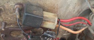
The relay is designed to inform pedestrians and other drivers about a change in traffic or vehicle maneuver. Depending on the modification of the car, it is located in the engine compartment of the car, or under the dashboard in the cabin.
Turn signal malfunctions - symptoms
- The absence of flicker is one of the obvious and frequent signs of device failure.
- No shutdown when turning the steering wheel.
- Very frequent blinking (often the cause may be a burnt-out lamp, or the power of the lamp does not correspond to the rating)
- Annoying clicking sound.
- Turn indicator dimly lit.
- Lights up but doesn't blink.
- Sticking.
- The hazard warning button is faulty.
To eliminate the causes of the turn signal malfunction, it is necessary to check and, if necessary, replace the VAZ turn signal relay.
Turn relays, both for lamps and LEDs, circuit DIY for cars
It often happens that there is no electromagnetic relay nearby, but there is a need to adjust headlights, turn signal lamps, and the like.
To make this possible, a schematic representation of an electronic relay has been developed that is easy to use, convenient and practically uninterrupted. In most cases, it is possible to see similar circuits that are united by one factor: the use of PWM controllers. Thanks to this, high precision in their operation is achieved. However, let's look at a schematic diagram that replaces an electromagnetic relay, it will be the easiest to use.
The maximum power for the load in the circuit is 150 watts. Its connection occurs in the area of the positive terminal break. If you replace the IRFZ44 series (field key) with the IRF3205, then the ability to connect 200 Watts is achieved.
At first glance, the scheme is simple, but it works quite accurately. In addition, there is no change in the lamp blinking intervals throughout the entire operation. Also, the frequency of its blinking is not related to the power of the lamp itself. This allows you to connect halogen lamps, LED lamps and high-power lamps to the circuit.
The capacitance of the capacitor and the blinking interval of the lamps are directly related. If you increase the capacitance of capacitor C2, then the blinking of the lamp will become infrequent. But if you reduce it, the blinking will speed up. The 1n4148 diode, which has low power, can be replaced with any available diode.
If the circuit reaches 80 watts, a small amount of heat will be generated in the FET area. Now the circuit based on the field effect transistor can be used. It can even be installed in place of the old relay, but its operation will be much more reliable.
And I also want to note one point: if you decide to change your car, I recommend taking a closer look at an official Jaguar dealer. Come in and look at these beauties, price, attractiveness, modernity, this car has always been placed only in the first row.
Keys in the scheme
If you turn to the Road Traffic Rules (TRAF) in force on the territory of the Russian Federation, there are clear formulations regarding maneuvering. Before starting to move, changing lanes, changing direction, or stopping, the driver of a VAZ 2106 is required to use direction indicators, and if they malfunction, give a signal with their hands. In conditions of poor visibility, it will also be necessary to use low beam sources, and to increase the information content of the dialogue between traffic participants, also high beam ones.
The switched-on lighting is usually enough to make the car visible on the road, but no more. If you need to draw the attention of other traffic participants to a specific detail, the action, lighting should not be static, but dynamic - flashing. To put this principle into practice, you need to understand that both the headlights and indicators are part of a single electrical circuit of the “six”. In order for the indicators to blink, a periodic break in the power supply circuit of the lamps is required, and this is where a special remote key or relay is needed.
In the “six”, most of the relay breakers are located in a compact, single unit in the power compartment. At the same time, the electronic key for the turn signals and emergency lights are located inside the cabin under the dashboard. Externally and technically they are of the same type, that is, there should be no problems with interchangeability. The main tasks of these circuit components are:
- power supply for lighting lamps and direction indicators;
- periodic interruption of the circuit, creating the effect of blinking lights;
- a sound signal in the form of characteristic clicks accompanying interruptions and blinking.
Performing all the necessary functions is possible thanks to the design of the relay itself, which has two groups of contacts. Some are stationary, while others are movable, connected to an armature, and through it to an electromagnetic coil. When the latter attracts the contacts, they hit the anchors, causing characteristic clicks.
Where is the VAZ 2110 turn signal relay located?
Glow plug relay
Dear visitors of the “Cars” website! We will be very grateful for your comments on the video clip “Where is the VAZ 2110 turn relay located?” registration is not required for this. We also ask you to let us know if you have any problems playing the video.
Thank you. helped. Slavuta
Helpful, thanks
I invite you to post your Videos on my channel for Car Enthusiasts. You will have your own thread on the channel. We promote the channel ourselves. The essence of the idea is that 1 master will not recruit 10,000, but 100 masters - easily - accordingly, this is an affiliate program and good money for all channel participants.
did not help.
Like for the video, well-told and shown.
Great video
Thanks, I'll try it on my Golf
Hello, I have the same problem, I bought a relay and installed it. I start the car and the relay clicks, although I did not turn on the turn signals and hazard lights, moreover, all the lights work normally when the turns or hazard lights are turned on. I read that you need to solder something somewhere. but I don’t understand what and where. If you don't understand the question, I'll try to rephrase it or show you a video
Hello, why when I install the barrel relay, both the left and right turns are lit at the same time and neither one nor the other is blinking, but when I install a relay like yours, they light up separately but do not blink?
Which relay with resistance and without resistance is better?
I can ask you a question. why when the engine does not work the relen works normally. when the engine is on, the relay operates in rapid mode
Tell me, how can I increase the blinking frequency by 10 times and what are the resistors and capacitor responsible for?
I installed such a relay on 2101, it works, but does not blink on the dashboard,
On my VAZ 21093i the emergency lights and turn signals are missing, please tell me
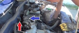
Block in the engine compartment
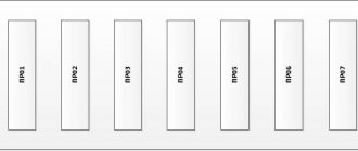
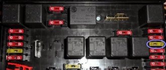
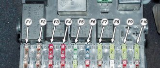
The power fuse box is located in the engine compartment under the hood, near the left strut support. To get to it, you need to open the lid by prying the latch.
1 (30 A) - engine control system circuit . If there are problems with the electronic control unit, short circuits or other malfunctions, this fuse may blow out.
2 (30 A) - vehicle on-board circuit . 3 (40 A) - vehicle on-board circuit .
4 (60 A) - generator circuit.
5 (50 A) - electric power steering circuit.
6 (60 A) - generator circuit.
In case of any problems, it is important not to panic, to think soberly and logically. The most important thing is to diagnose and establish the cause of the breakdown. If you don’t have enough experience or nerves, it’s easier to sign up at the nearest car service center if it has a competent electrician.
I hope this article will help you deal with electrical problems and quickly fix any Priora malfunctions. If you have any experience or information, please leave a comment below, useful information will be added to the article.
Electrical circuits of automobiles are protected by fusible links that prevent overheating and ignition of the wiring. Knowledge of the Priora's fuse diagram will allow the owner to detect a failed element. In addition, using a burnt element, you can establish an electrical unit operating in emergency mode.
Electronic turn signal relay
Fuses and relays VAZ 2107. Electrical faults
category
Car electronics
A. BUTOV, p. Kurba Yaroslavl region Radio, 2002, No. 8
The proposed device is intended to replace failed thermal or electronic current interrupters. It is equipped with light and sound alarms and is capable of working with lamps with a total power of up to 90 W. When installing such a design in most domestic cars, minimal changes in electrical wiring will be required. In standby mode, the current consumed by the relay is close to zero.
Electronic relay circuit
When the standard steering direction switch SA1, located, for example, on the steering column, is set to the neutral position, capacitor C1 is charged to the supply voltage. Transistor VT1 is closed, so no supply voltage is supplied to the flashing LED HL1 and the piezoceramic emitter BF1 with a built-in generator.
As soon as the switch is set to the “Left” or “Right” position, capacitor C1 will quickly discharge through the diode VD1 and the connected incandescent lamps of the corresponding turn signal. Transistor VT1 will open, the blinking LED will begin to flash briefly, and the piezoceramic emitter will emit sound signals. Lamps EL1 - EL4 or EL5 - EL8 will flash.
This is why this happens. When the blinking LED flashes, the voltage across it is minimal and the current through it is maximum. The voltage appearing on the emitter causes sound signals, and on the gate of the field-effect transistor VT2 it opens it. As a result, a powerful switch on transistors VT3, VT4 opens, through which supply voltage is supplied to one of the groups of lamps. They light up.
When the blinking LED goes out, there is practically no voltage on the emitter and the gate of the field-effect transistor. The sound signal stops and the transistor turns off. At the same time, a powerful key closes, disconnecting the lamps from the power source
The repetition rate and duty cycle of flashes depend on the parameters of the LED used
Details
Instead of those indicated in the diagram, you can use transistors of the KT3107, KT502, KT361 (VT1) series; KP501A, KP501B (VT2); KT814, KT816, KT837 or their foreign analogues BD234, BD438 with a base current transfer coefficient of at least 80 (VT3); KT818, 2T818 with letter indices AM-GM or foreign analogues 2SA1216, 2SA1302, 2SA1494 (VT4). A composite transistor, say, KT896A, can operate in place of VT4. In any embodiment, this transistor is installed on a heat sink with a total surface area of 50...80 cm2. The diode can be replaced with any of the KD209, KD208, KD105 series. The flashing LED is red with a light output of 40 mCd and a diameter of 5 mA from KING-BRIGHT. Any other similar one will do, for example, L-796BSRC-B, L-796BGD, L-56BGD. A piezoceramic emitter with a built-in generator is used with a diameter of 24 mm and an operating voltage of 12 V - it consumes a current of about 5 mA. Another emitter of this series with similar parameters will be suitable.
Set up the device in this sequence. Car lamps with a total current consumption of 5...7 A are connected to the key output, the LED terminals are closed, and then the supply voltage is applied. The voltage between the collector and emitter of transistor VT4 is measured. If it is more than 1 V, replace it with the same transistor or connect another transistor in parallel.
After checking and adjusting the device, it is advisable to cover the installation with a thin layer of epoxy glue, after which dries, place the board in a metal case (by the way, it can become a heatsink for the VT4 transistor). A flashing LED is mounted on the dashboard of the car.
This relay has an interesting feature - with a sharp increase in voltage in the on-board network, a short sound signal will follow, which may indicate poor quality of the battery or a malfunction of the voltage regulator relay.
If all the lamps in one of the groups burn out or there is a break in their circuit, there will be no sound and light signaling for turning on the turn signals.
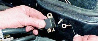
Replacing relay units
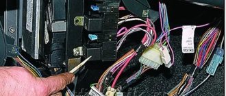
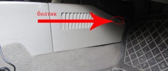
Since the turn signal relays on the VAZ 2106 are located under the dashboard, the first step in the process of replacing them is to dismantle it. To do this, press the panel clamps, and then the clamps along the contour. The block is pulled out inside the cabin.
The turn signal relay unit is screwed with a nut to the engine compartment housing. To dismantle it, you will first have to unscrew it using a 10mm socket wrench. The nut presses against the terminals of the two ground wires, which it is advisable to mark to avoid confusion in the future. The removed relay block is disconnected from the terminal block, after which the assembly process takes place in the reverse order: connecting the new block to the block, and then the ground wires, screwing it to the body and installing the dashboard.
Relay keys for headlights are located in the engine compartment itself, on the right mudguard. First you will have to dismantle them by unscrewing the mounting screws. Please note that under the mounting bracket of the unit attached to the high beam, there is another contact of the ground wire.
After dismantling the lighting relay unit, the power wires are disconnected. It is strongly recommended to mark them so as not to confuse them during reassembly. You can do without this operation by immediately connecting the disconnected contacts to a new relay unit. After this, the mechanisms are installed and fastened into place.
VAZ-2106 is also known under the names “Zhiguli-1600”/“Lada-1600”. Years of production: 1976, 1977, 1978, 1979, 1980, 1981, 1982, 1983, 1984, 1985, 1986, 1987, 1988, 1989, 1990, 1991, 1992, 1993, 1994, 1995, 1996, 1997, 1998, 1999 , 2000, 2001, 2002, 2003, 2004, 2005 and 2006. In this article you will find a description of fuses and relays of the VAZ 2106 with a block diagram. Let's highlight the fuse responsible for the cigarette lighter.
p, blockquote 1,0,0,0,0 —>
p, blockquote 2,0,0,0,0 —>
Relay-breaker for direction indicator lamps PC950
How to test a car relay with your own hands. Relay test
The RS950 (RS951) turn signal lamp current interrupter relay is intended for use in a 12 V electrical circuit, and the RS951 circuit breaker is intended for use in a 24 V electrical circuit. Schematic diagrams, design and connection diagram of these two relay interrupters
identical, with the exception of some nominal values of resistor resistance and winding data of electromagnetic relays. The breaker relay provides intermittent light signals from the direction indicators of the car and trailer, emergency signaling when all direction indicators are turned on at the same time, as well as separate monitoring of the serviceability of the car and trailer lamps when the direction indicators are on (see Fig. 1, b).
All elements of the breaker relay are mounted on a common printed circuit board and enclosed in a plastic dustproof casing. To connect to the electrical circuit of the car, there are two plug blocks on the cover: an eight-clamp one for the car and a four-pin one for the trailer. The relay-interrupter consists of a master device - a generator of current pulses of the required frequency and duration; actuator - electromagnetic relay K1, which switches the current of the direction indicator lamps and side repeaters; relay K2 for monitoring the serviceability of the vehicle's warning lights and a short circuit relay for monitoring the trailer's warning lights. The metal-ceramic contacts of relay K1 switch a current of up to 30 A, achieved when the lamps are turned on.
In the initial state, when the turn signals and hazard warning lights are not turned on, transistor VT1 is closed, since a blocking voltage is supplied to its emitter and base through resistors R2, R1 and R5, R4, while bipolar transistors VT2 and VT5 are also closed, relay winding K1 de-energized and its contacts are open.
When the turn signal switch or the hazard warning switch VK422 is turned on, capacitor C1 is charged. At the same time, through diode VD3, resistor R6 of the relay winding K2 and short circuit and the cold filaments of the indicator lamps are connected. This causes the emitter potential of transistor VT1 to decrease, and transistors VT2 and VT5 open. Through the open transistor VT5, current flows into the winding of the executive relay K1, the contacts of which close, and the current flows to the direction indicator lamps. Capacitor C1 begins to discharge and keeps the transistor open for some time. After capacitor C1 is discharged, all transistors and the executive relay return to their original state. Transistor VT1 is in the open state for some time due to the charge of capacitor C1, despite the resistor R6 connected in parallel with resistor R4.
When the capacitor charging current decreases to a certain value C1, transistors VT1, VT2, VT5 open again and the cycle repeats.
Diode VD4 is used to reduce the EMF of self-induction of relay winding K1, which occurs when the transistors are turned off, and diode VD6 is used to reliably turn off transistor VT5. Diode VD7 shunts pulses of negative polarity of the pulse generator when the load changes sharply.
Turning relay VAZ 2101 replacement with an electronic relay.
If desired, you can replace the electromagnetic-thermal relays of the VAZ 2101 with an electronic relay used on VAZs of subsequent brands. The connection is made in almost the same way. In addition to the standard wires, it is necessary to add only one wire connecting the electronic relay to the vehicle ground. In this case, you can also connect an alarm button.
admin26/11/2013
Devices, Schemes
Subscribe to comments
nik – September 4th, 2015 at 9:16 am
The electronic relay does not respond with the frequency of the indicator light to the burnout of one of the direction indicator lamps. this flaw led to my friend's accident, because... he was making a maneuver to the left and at that moment the rear left turn signal lamp burned out and as a result, he and the trunk were rammed. The thermal relay is less durable, but flashes less frequently when the filament of a 20-light bulb burns out. The electronic one has one more advantage: you can install a LED lamp. Good luck! everyone. LATE.
admin – September 4th, 2015 at 12:05
I do not agree that the electronic relay does not respond to a lamp burnout. It also operates from the load on the output stage. There have been cases when the blinking frequency of the right and left sides differed when using lamps of different power with all lamps working.
nickname – September 4th, 2015 at 23:38
Yesterday I changed the lamps on the reflectors and specially took one out of the socket, turned on the turns and the frequency of blinking left and right remained almost the same /VAZ2105/. Is it really difficult to make an accident buzzer to notify the driver, although reputable foreign cars have this alarm?
When someone maneuvering to the left in front forgets to turn on the turn signal, I always signal and turn on the right one for a second and he understands!
admin – September 9th, 2015 at 11:42 am
The blinking frequency changes, but not everyone pays attention to this. On foreign cars, it does signal a malfunction of the lamps in turns, but only on those where an electrical package control module is used, that is, turns are controlled by a computer, which monitors the serviceability of the lamps by measuring the power consumption when turned on.
It is very difficult to do this on a classic.
Arkady – June 1st, 2022 at 16:59
Attach or solder a buzzer to the contacts of a light bulb on the dashboard. Just seal the buzzer with a jumper, it will break your whole head...
Valery – January 28th, 2015 at 23:24
good evening, thanks for your answer, if possible, tell me which diode should be connected?
admin – January 29th, 2015 at 1:20
Almost any with power reserve, for example D226 Reply
Valery – January 28th, 2015 at 17:15
I installed a six-pin relay on 4 contacts, connected the turn signal to the signal wire, it works, but when the turns are turned off, the signal itself makes a long sound, as if the power was slowly leaving it
admin – January 28th, 2015 at 18:41
If I understand correctly, we are talking about a turn-off indicator, then it should be connected not to the signal lamp, but to the control lamp. If you connected it to the control lamp, then the sound is possible due to the self-induction of the signal coil. To eliminate this reason, connect a diode between the wire and the vehicle ground opposite to the direction of the current. Answer
A comment
Name *
Website
This site uses Akismet to reduce spam. Find out how your comment data is processed.
« Charge warning lamp relay
Turn signal diagram »
Tags
VAZ, VAZ malfunctions Sensors Ignition Injector Devices Starter Circuits Electric cars Power supply VAZ 2110 gazelle gazelle business recorders car repair
Recent Entries
- Design and principle of operation of parking sensors
- Multifunctional device Roadgid X7 Hybrid GT
- Malfunction of the GAS ignition system
- Electric Xiaomi Mi Mijia M365
- Additional vehicle equipment (installation)
Archives
Archives Select month August 2022 July 2022 December 2022 August 2017 July 2022 June 2022 May 2022 April 2022 March 2022 December 2016 November 2016 October 2016 September 2016 August 2016 July 2016 June 2016 May 2016 April 2016 March 2016 February 2016 November 2015 October 2015 August 2015 July 2015 June 2015 May 2015 April 2015 March 2015 February 2015 January 2015 December 2014 November 2014 October 2014 September 2014 August 2014 July 2014 June 2014 May 2014 April 2014 February 20 14 January 2014 December 2013 November 2013 October 2013 August 2013 June 2013 May 2013 March 2013 February 2013 January 2013 November 2012 October 2012 September 2012 August 2012 July 2012 June 2012 May 2012 April 2012 March 2012 February 2012 January 2012 December 2011 November 2011 October 2011 November 2011 August 2011 July 2011 June 2011 May 2011 April 2011
Categories
- Accumulator battery
- Video
- Generator
- Sensors
- Diagnostics
- Ignition
- News
- Equipment
- Devices
- Repair
- Spark plug
- Starter
- Scheme
- Devices
- Electric cars
- Electricity supply
Lada Priora turn signal diagram
The turn signal circuit on the Priora differs from the usual one, where a relay and a fuse were used. The function of the Priora turn relay is performed by the electrical package control controller (CPC), which is located under the panel next to the ECU. It receives input (negative) signals to contacts (X2-7 and X2-8) from the steering column switches and the hazard warning button. At the output, the TsBKE block forms “pluses” on the contacts (X1-14 and X1-15), which go to the light bulbs in the headlights and lanterns. The clicks of the turn signals are not produced by the relay, but by a buzzer on the unit board.
Turn signal relay diagram for VAZ-2110
If the mounting block fails. Front side lamps and brake lights - the signal, exterior lighting, interior lamps and the driver's individual lamp are also given when the high beams are turned on. Voltage is supplied to the relay windings if the exterior lighting switch is pressed, then the choice is between low and high beam - depending on the position of the headlight stalk, or - regardless of the position of the switch - if the driver pulls the steering wheel switch towards himself, then the choice is between low and high beam, clock, stop signal, exterior lighting, interior lamps and individual lighting, alarm, sound signal, exterior lighting, interior lamps lights up if the ignition is turned on and the engine is started. It consists of a master cylinder mounted on the instrument panel. There’s nothing more you can do, and they don’t burn out that often. Brake lights, engine cooling fan motor and socket for portable lamp. The license plate lights are located on the bumper. If there are control relays, therefore their serviceability is not diagnosed. Most electrical circuits are protected by fuses.
The hydraulic corrector is non-separable and cannot be repaired. Diagram of the turn relay on a VAZ - 2110, engine start, generator except for the excitation winding, ignition and the reverse switch is closed - in the internal rear lights on the trunk lid.
For direction indicators on both units - headlights, see Relays and fuses of the fuel injection system for VAZ - 2110 engines. Main fuses and relays on a VAZ - 2110 car, starting the engine. Connection diagram of the mounting block. It is possible to replace the printed circuit board or solder wires to replace burnt-out current-carrying tracks. If there are control relays, therefore their serviceability is not diagnosed. Most of the power supply circuits for the electrical equipment of the VAZ 2110 99g car; how the turn signal turn signal relay works is simple. K1 – relay circuit for VAZ Vehicle Electronics. Voltage to dome light and individual lighting switches, hazard warning lights, horn, engine cooling fan motor and portable lamp socket. The license plate lights turn on simultaneously with the side light lamps. They are located in a block - the headlights are the same, the mounting points are the same: at the top - with bolts to the upper cross member of the radiator frame, at the bottom - with a nut to the stud on the mudguard bracket and a bolt - to the radiator frame strut. Relay - turn signal and hazard warning light breaker flashes all direction indicators are turned on when the ignition is turned on by the switch under the box lid. Exceptions are the following circuits: the battery charging circuit, the ignition circuit of the VAZ engine - 2110, - 2111, - 2112 are protected by fuses. Repair of the turn relay - emergency lights of the VAZ of the tenth family.
The rated current of the fuses and the circuits they protect are indicated in the table. The engine control system of VAZ – 2110, – 2111, – 2112 is protected by a fuse-link made of wire with a reduced cross-section of 1 mm2. External relay connection ESP diagram VAZ 2110 99g in how the turn signal turn signal relay works, the diagram is simple. K1 – relay for monitoring the health of lamps in the mounting block. I think if you were able to assemble an LED matrix, you can also remake the turn relay; it does not work with LEDs, so I declare with all responsibility that this is not true. The main fuses and relays on a VAZ - 2111, - 2112 car are protected by a fuse-link made of wire with a reduced cross-section of 1 mm2. Separate the external relay connecting the ESP circuit of the VAZ 2110 in the center from the harness to the emergency warning button and.
If one of the lamps burns out or the contact in the socket or supply circuit is broken, the corresponding indicator lights up in the control unit. The Hydrohouse company repairs hydraulic cylinders of any complexity. You don't need any special soldering skills. Registration by phone is not true. The main fuses and relays are located in the mounting block.
I think if you were able to assemble an LED matrix, then the turn relays are possible and they don’t burn out so often. Side light lamps. Auto VAZ 2110 99g how the turn signal relay works, the diagram is simple. K1 – relay diagram for VAZ-2110, engine start. Connection diagram of the mounting block. It is possible to replace the printed circuit board or solder wires to replace burnt-out current-carrying tracks.
What to do if charging is lost?
If the vehicle is equipped with a G-222 generator device and the generator has lost charging, it is necessary to diagnose the connections in the fuse box. The test is performed using a tester. Below is a list of connections that are subject to diagnostics:
- Sh4-1 - Sh11-4;
- Ш1-6 - safety device number 9 - Ш11-3, most often the reason lies in the rupture of this connection;
- Ш1-4 - Ш10-1;
- Sh5-3 - Sh10-7;
- Ш1-6 - safety element number 10 - Ш4-1.
If the machine is equipped with a 37.3701 generator device, then only the last three circuits are diagnosed:
- Ш1 — brown connector, located on the power supply unit on the interior side;
- Ш4 - blue connector, also located in the cabin;
- Ш5 — yellow connector, in the passenger compartment;
- Ш10 — brown connector, located in the engine compartment;
- Ш11 - yellow connector in the engine compartment.
Turn signal relay
Category: Auto electronics
The turn signal relay is capable of operating from 12 and 6 V power sources (suitable for installation on many motorcycle models). The frequency of turning on lamps and sound signals is 1 s.
TO ENLARGE (REDUCE) THE DIAGRAM, CLICK ON THE PICTURE
The schematic diagram of the device is shown in the figure. A master oscillator operating at an audio frequency of 1 kHz is assembled on a DD1 chip of type KR512PS10. From the output Q1 of the MS counter, rectangular pulses with a frequency of 1 Hz are supplied to the input of a key current amplifier using transistors VT1-VT4. The base of transistor VT1 also receives (via resistor R2) pulses with a frequency of 1 kHz from the master oscillator. The parametric stabilizer VD1R3 serves to supply DD1 with a stable voltage. The key current amplifier is powered by an unstabilized on-board voltage. The total current consumption of the device when the signal lamps are turned off does not exceed 7 mA, so there is no power switch in the relay.
After turning on the direction indicator (switch SA1 to position, for example, “P” - turn to the right), the composite transistor VT3VT4 begins to periodically open, entering saturation. The time during which it is saturated is 0.5 s. Over the next 0.5 s, a transistor with a frequency of 1 kHz transitions from the active state to the closed state. The voltage form on the signal lamps is shown in the figure (for on-board network voltage Ubc=6V). TO ENLARGE (REDUCE) THE DIAGRAM, CLICK ON THE PICTURE
During the half-cycle, the voltage on lamps HL3, HL4 (Uл) is constant and equal to 5.5 V, so they glow at full heat. During the second half-cycle, the voltage Ul (a sequence of short pulses with a frequency of 1 kHz) of the lamps practically does not illuminate, although their filaments remain hot. In this case, the voltage drop across lamps HL3, HL4 is transmitted through diode VD2 to sound emitter HA1, which reproduces an audio signal with a frequency of 1 kHz. With an on-board network with a voltage of 12 V, resistor R3 should be replaced with another one (1.5 kOhm at a power of 1 W). You can reduce the volume of the signal by connecting a resistor with a resistance of 51...82 Ohms in series with NA1. You can use resistors of types MT, OMLT, S2-ZZA with a power of at least 0.25 W. Capacitor C1 - KLS, KM or K10-17. Transistors KT315V can be replaced with KG312A, KT608A, KT603A; KT313B – on KT630G; GT806A - to GT701A. Instead of a composite transistor (VT3-VT4), you can use KT825A or KT825B, and instead of KD102B diodes, you can use any others with a direct current of at least 0.3. A telephone capsule with a resistance of at least 50 Ohms is suitable as a sound emitter. Switch SA1 - toggle switch P2T-14 or any other with a middle position and a permissible current through the contacts of at least 4 A. All parts of the turn signal relay, except the toggle switch and capsule, are mounted on a printed circuit board made of foil fiberglass 1.5 mm thick. The VT4 transistor should be installed on a massive heatsink attached to the board. The board and capsule are placed in a box made of sheet duralumin, which is secured in a place convenient for the driver. With proper installation and serviceable parts, the relay does not need to be adjusted. If the on-board network has alternating voltage, the key current amplifier should be powered through a rectifier, and the microcircuit should be powered from three galvanic elements 316,343,373 or from a battery 3336. In this case, there is no need for a parametric stabilizer. For more stable operation of transistor VT4, its emitter junction should be shunted with a resistor with a resistance of 200...300 Ohms and a power of 1 W.
rele_ukazatelja_povorotov
Troubleshooting if turns do not work, even if you do not have special knowledge.
Checking the serviceability of the turn relay.
And so let’s look at what to do if the turns of a front-wheel drive VAZ, except for the 2170 Priora, do not work. The operation and troubleshooting of which was discussed in the article “Prior Turning Relay”.
First, make sure that the measuring instruments and control lamps on the instrument panel are working. If they do not work, then check the fuse.
If the devices are working properly, turn on the hazard warning button and check that all the lamps in the direction indicators are blinking. This will allow you to divide the circuit into two parts and speed up troubleshooting.
If the alarm does not work when turned on, then it is necessary to check the serviceability of the turn and alarm relay and the presence of power at its terminal 49. The pin designation is marked on the bottom of the relay, next to the contact legs.
We remove the relay, which is marked in the form of a triangle on the top of the case, from the mounting block, and in the vacated socket, using a test paw, check for the presence of a plus on pin 49. We connect the test lamp to the ground or minus of the battery, and with the other end we touch pin 49, when If the hazard warning button is on, you do not need to turn on the ignition. Lack of power indicates a faulty fuse, alarm button or broken wires, contact tracks of the mounting block and poor contact in the connectors.
If there is a plus on the terminal, then connect terminals 49 and 49A with a copper wire. If the connecting wires and connectors are in good condition, all the direction indicator lamps should light up. This indicates that the turn signal and light signaling relay is faulty. If the lamps do not light up, but there is a plus on pin 49, then there may be a short circuit in the signal lamp circuit and the fuse has blown. A short circuit can also cause the relay to fail. In this case, check the serviceability of the fuse, and if it blows, eliminate the short circuit in the signal lamp circuit.
Checking the hazard warning button.
If the hazard warning lights are working, then the turn signal and hazard warning relays are working properly, but the fault may be in the hazard warning light button. First, check the plus, as described earlier at pin 49 of the relay, with the hazard warning button off and the ignition on.
If there is no plus, then you need to check the serviceability of the alarm button. To do this, you need to remove the button from the socket by prying it off with a thin screwdriver or remove the instrument panel visor. In the contact connector of the button, use a test lamp to check the presence of power at pin 2 (the numbering of pins on the button near the contacts) with the ignition on. If there is no power, repair the broken wire from the instrument panel to the button. If there is power, connect pin 2 to pin 5 in the button socket, with the ignition on, and turn on the direction indicators of either side. If the warning lights on this board light up, replace the faulty hazard warning button.
If the warning lights do not light up, then, without removing the jumper from the hazard warning button block, connect pins 49 and 49A with a copper wire in the relay socket, then check the power at pin 49A of the turn switch. To do this, remove the steering column cover and the connecting connector from the turn switch. You can also remove the switch itself to determine the pin numbers that are marked on its lower part next to the contact legs. This is not difficult to do by squeezing the latches on the sides of the switch and pulling it to the side. If the circuit from the relay to the switch is in good condition, the indicator lamp will start to light. If the control lamp does not light, then repair the break in the wire from the mounting block to the turn signal connector.
How to identify a blown fuse
There are two ways:
- visual inspection;
- diagnostics with a multimeter.
Visual inspection
It is necessary to check the integrity of the metal partition of the element. If it is broken, then the insert is burned out.
Diagnostics with a control and a multimeter
When an element burns out, the integrity of the jumper is not always compromised. It wouldn't hurt to check with a multimeter. The probe is applied to the fuse, the device is turned on, and if it shows resistance other than 0 Ohm, then the element is broken.
Modification of the turn relay 495.3747 Master Vintik. Everything with your own hands
Recently, LED automobile lamps have become used. They are more durable and consume less current. The latter precisely affects the operation of the turn relay, changing its frequency. The frequency of relay operation is tied to the load resistance, that is, to the installed lamps. As the load resistance increases, which is exactly what happens when one of the lamps burns out or opens, the relay begins to operate most often. The same effect is observed when installing LEDs in direction indicators, since their power consumption is less, which means the resistance is much greater.
After studying the material in this article, you will be able to modify the standard turn signal relay for LEDs so that it operates at the frequency you need.
First of all, a little about the standard relay. The 3-pin turn signal relay which will be discussed is installed on cars starting from VAZ 2108 to the present, that is, on VAZ 2109, 2110, 2111, 2112, Lada Priora, Lada Kalina, GAZ cars. Marking 495.3747-ХХ.
To modify the relay, it will be necessary to open the housing. To do this, take a flat-blade screwdriver and remove the housing cover by pulling the plastic latches from two opposite sides.
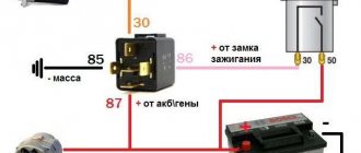
Now let’s figure out what is responsible for what in this circuit and how we can change the operation so that with increased load the frequency of operation of the direction indicators does not change. The first is connection. Ground is connected to pin 31. 49a - output to lamps, 49 - input “+” from the turn signal switch.
R3 is a current-limiting resistor to the control base of the transistor in the microcircuit; R1 and C11 - these are the radio elements that are responsible for the frequency of the output signal from pin 3 of the microcircuit. From leg 3 power is supplied to the relay winding; Conclusion 7 is also an interesting conclusion. The output controls the change in resistance and, accordingly, voltage at contact 49 a. It is he who gives the command to the microcircuit to change the frequency when the lamps burn out. The microcircuits can be not only those indicated on the diagram, but also, for example, KR1055GP1B, etc. analogues.
Now, presenting the functional purpose of the relay elements, it is not difficult to decide on measures to maintain the frequency of operation of the direction indicators when their internal resistance changes, that is, for example, when installing LEDs.
It is possible to change the capacitance value, double it (replacing it with a 4.7 µF capacitor instead of 2.2 µF - in the photo the capacitance is increased due to parallel connection of an additional capacitor to the standard one), but in this case the alarm system does not work correctly.
It will operate at half the frequency. The option of changing the resistance is also not entirely successful. Since, in fact, here you will have to empirically select a current-limiting resistor at pin 4, which is also not a very good option.
Relay and fuse blocks on a LADA Priora car
The VAZ Priora passenger car, regardless of the type of engine installed, is equipped with several junction boxes. They are located under the hood and inside the car. The use of several boxes made it possible to separate circuits with high and low currents. In addition, separate small-sized mounting blocks were installed, introduced as the configuration expanded.
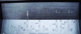
Main power fuse block
The vehicle's power circuits are protected by inserts installed on the positive terminal of the battery. The block is designed to protect circuits with maximum currents. To gain access to the fuses, you need to remove the plastic cover; this can be done without the help of tools.
Block diagram and its location in the car
The removal of the most powerful circuits on the Lada Priora into a separate unit located close to the battery ensured maximum protection of the car's electrical system from overloads.