Oka brand cars are equipped with cylindrical type fuses. Total number of modules: 10 pieces, relays - switches 5 pieces.
Due to ineffective design and outdated technology, fuses often fail and melting elements burn out. The process of replacing with new ones is not at all complicated, but it is not always rational. Many car enthusiasts practice installing knife-type modules. This is a modern design with a melting element in the center.
Installation of blocks is no more difficult than cylindrical ones; every car enthusiast can cope with the task.
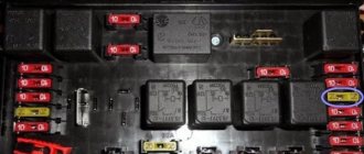
Fuse installation diagram
| Marking | Scheme |
| Fuse (1) / 15 | Stove heater |
| Fuse (2) / 10 | Fan activation sensor |
| Fuse (3) / 5 | Windscreen wipers |
| Fuse (4) / 5 | Carburetor solenoid valve |
| Fuse (5) / 15 | Turn signals. Alarm |
| Fuse (6) / 20 | Tail lights, oil pressure, battery |
| Fuse (7) / 20 | High beam, low beam, dimensions |
| Fuse (8) / 15 | License plate light |
| Fuse (9) / 5 | Power socket, interior lighting |
| Fuse (10) / 5 | Cigarette lighter |
The cost of the original fuse block assembly (hereinafter referred to as the BP) starts from 1,200 rubles. high-quality analogues from 800 rubles.
Relay block
On the left side under the instrument panel there is a block of five identical relays (90.3747-10 / 113.3747-10 / 2105-3747210-20)
Scheme
Designation
| 1 | Engine radiator fan relay |
| 2 | Low beam relay |
| 3 | High beam relay |
| 4 | Starter relay |
| 5 | Heated rear window relay |
Replacing fuses on Oka
The PSU installation process is quite simple and intuitive. At the preparation stage, we check the availability of:
- Collar;
- Heads on "10";
- A new old-style power supply unit (cylindrical type) or a knife type, if the owner decided to upgrade;
- Additional lighting as needed if work is carried out in conditions of limited visibility.
Replacement steps:
- Place the car on a flat surface, open the driver's door wide;
- We wedge the rear row of wheels with wheel chocks and squeeze the parking brake lever. This is necessary for personal safety during work;
- Open the hood, unscrew the power terminals from the battery to prevent a short circuit in the on-board circuit;
- We snap off the cover from the power supply unit and squeeze the plastic clips on the sides;
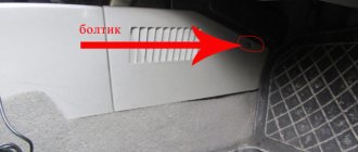
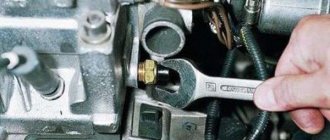
- Using a 10mm socket, unscrew the mounting bolts on the sides. We remove the power supply from the seat.
Next, we insert a power supply with knife-type fuses; if we are upgrading the equipment or identifying a faulty module, we replace it with a new one.
- Screw the bolts and put on the protective cover.
Checking and replacing the relay VAZ "OKA" 1111 1988-2008
- Repair manuals
- VAZ "OKA" 1111 1988-2008
- Checking and replacing the relay
You will need: 8 key, screwdriver.
| 1. To replace the relay for turning on the starter, low and high beam headlights, heated rear door glass, electric motor of the cooling system fan, ignition, unscrew the nuts securing the fuse box and move it to the side without disconnecting the wire ends from it (see “Removing and installing the block fuses"). |
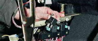
| 2. Unscrew the fastening screw and remove the relay from the body bracket (all listed relays are removed in the same way). | 3. Remove the relay from the connecting block. |
| 4. To test the relay, connect it according to the diagram to an external 12 V power source (for example, to a battery). If the relay is working properly, the lamp should light up. If the lamp does not light up, replace the relay. |
| NOTE Relay for turning on the starter, low and high beam headlights, heated glass of the rear door, electric motor of the cooling system fan, ignition of one type 90.3747–10. The relay marking (type, manufacturer's trademark and contact layout) is printed on the housing cover. |
| 5. Install the new relay on the connection block and secure it to the bracket with a screw. | Ignition switch relay |
(type 90.3747–10) is located under the instrument panel to the right of the steering column. To replace it, follow steps 3 and 4.
The parking brake warning lamp relay, type PC492, is located under the instrument panel to the left of the steering column.
The relay marking (its type and manufacturer's trademark) is printed on the housing cover.
| 6. Label the wires and relay housing cover. |
| 7. Disconnect the wire ends from the relay and remove it. |
| 8. Install the relay in the reverse order of removal. |
The PC514 windshield wiper relay is installed under the left side trim.
The relay marking (its type, manufacturer's trademark) is printed on the housing cover.
| 9. Using a screwdriver, pry up the two upholstery fastening pistons (one is shown) and... | 10. ...remove the body side trim. |
| 11. Bend the floor mat to the side and... | 12. ...unscrew the two screws securing the relay to the side of the body, remove the relay from the side of the body. |
| 13. Disconnect the connecting block of the wires going to the relay (under the instrument panel) and remove the relay from the car. |
| 14. Install the relay in the reverse order of removal. |
The turn signal and hazard warning relay, type 494.3747, is located behind the instrument cluster and is attached with a nut to the front panel stud.
The relay is marked on the cover of its housing.
| 15. Press out the two spring latches located on the sides of the instrument cluster from the inside of the instrument panel, and... | 16. ...remove the combination from the instrument panel. |
| 17. Unscrew the speedometer cable fastening nut and disconnect the speedometer cable from the instrument cluster. | 18. Mark the pads and wire connectors, disconnect the pads from the instrument cluster and remove the combination. |
| 19. Unscrew the relay mounting nut and remove the relay from the body front stud. | 20. Disconnect the relay from the wire block (shown by the arrow). |
| 21. Install the relay in the reverse order of removal. |
↓ Comments ↓
VAZ-1111-11113 OKA
Section 1. VEHICLE STRUCTURE
General information about cars Vehicle registration data
Section 2. ENGINE
Possible engine malfunctions, their causes and solutions Useful tips Replacing the coolant Replacing the engine oil and oil filter Cleaning the crankcase ventilation system Setting the piston of the first cylinder to the TDC position of the compression stroke Adjusting the tension of the camshaft drive belt Replacing the tension roller Replacing the camshaft drive belt Removing, installation and troubleshooting of the flywheel Replacement of engine seal parts Cylinder head Adjustment of clearances in the valve drive Removal and installation of the engine Engine repair Lubrication system Cooling system Exhaust system Power supply system
Section 3. TRANSMISSION
Clutch Gearbox Front wheel drives
Section 4. CHASSIS
Front suspension Rear suspension
Section 5. STEERING
Inspection and check of the steering system on the vehicle Steering column Steering mechanism Steering linkage
Section 6.BRAKE SYSTEM
Checking and adjusting the brake system Replacing the brake fluid Bleeding the brake system hydraulic drive Master cylinder Brake vacuum booster Pressure regulator Replacing brake hydraulic hoses and pipelines Front wheel brakes Rear wheel brakes Parking brake
Section 7. ELECTRICAL EQUIPMENT
Fuses and relays Generator Starter Ignition system Lighting, light and sound alarms Windshield wipers and washers Engine cooling fan Instrument cluster Switches and switches
Section 8.BODY
Possible body malfunctions, their causes and solutions Replacement of buffers Hood Side door Rear door Rear view mirrors Seats Heater Body care
Applications
Appendix 1. Tightening torques for threaded connections Appendix 2. Fuels and lubricants and operating fluids Appendix 3. Basic data for adjustments and control Appendix 4. Filling volumes, l Appendix 5. Oil seals Appendix 6. Layout of rolling bearings Appendix 7. Car electrical diagram : 1 — side turn signal repeater; 2 — front direction indicator; 3 - headlight; 4 — electric motor of the cooling system fan; 5 — sound signal; 6 - sensor for turning on the electric motor
How to identify a blown fuse
It is quite simple to assess the condition of cylindrical type modules, as well as knife type ones. In both cases, a melting element is laid in the center of the fuse.
As soon as the current exceeds the permissible value, the plate instantly melts, opening the contacts. A small black spot forms, which is evidence that the part is faulty.
The module is removed from its seat using special plastic tweezers. In life, an accessory is often lost, so it is practiced with your fingers. After replacement, we put the power terminals on the battery, start the engine, and test the system.
Division by function
By function, all electrical equipment is divided into systems that perform specific tasks:
- Participate in engine operation;
- Ensure traffic safety;
- Create comfortable conditions;
There are also systems designed to maintain the health of the electrical circuit itself.
Systems responsible for engine operation
The ignition system is involved in the operation of the engine and its task is to generate a spark in the engine cylinders to ignite the air-fuel mixture. The components of this system are a switch, spark timing sensor, coil and spark plugs. The system is activated by the ignition switch. All these components are connected by a circuit, the diagram of which is presented below:
The second electrical system that works with the engine is the starting system. To start the engine, a power electric motor is used - a starter, controlled by the ignition switch itself. Its diagram is as follows:
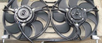
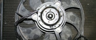
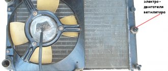
In relation to the engine there is also a cooling fan.
Systems responsible for safety and comfort
Electrical equipment that ensures traffic safety includes:
- Light and sound alarm (turn indicators, brake lights, reversing lights, sound signal);
- Main light (headlights, PTF);
- Heaters, window cleaners and washers;
These devices are combined into several systems. Below is the power supply diagram for only one of them - the turn signals:
Since the Oka is a budget car, there are not so many electrical appliances that create comfortable conditions for the driver. These include the heater (which includes the fan motor), the inner cover and the cigarette lighter.
Please note that in addition to creating convenience, the stove also affects traffic safety: in winter it heats the windows.
Since devices responsible for driving safety and comfort are not always required, they are disabled by default and activated by switches and switches.
In addition, the on-board network includes a battery recharging system, which is a component whose task is to maintain the operation of electrical equipment. Its connection diagram is as follows:
Common causes of fuse failure
- Systematic (periodic) power surges in the network;
- Oxidation of contacts on terminals, end switches;
- Damage to the insulating layer of the wiring, which leads to a “short-circuit” to ground, the car body;
- Damage to the body, impact, collision with oncoming traffic;
- Water entering the housing, condensation formation;
- Installing the module in a low current range;
- Unprofessional installation by the owner of the equipment.
Maintenance, repair
Of all the household appliances in the car, only power supplies need help:
- Battery (periodic recharging via a charger, monitoring the level and density of the electrolyte);
- Generator (periodic check of the transmitted voltage, replacement of worn graphite brushes).
It is also important to monitor the condition of the wire insulation and prevent damage to it to avoid a short circuit. Often, oxidation of contacts occurs in wiring connections, which can lead to failure of electrical appliances.
Most electrical components do not require maintenance and must be replaced if they fail. Such elements include light bulbs, small electric motors, switches, relays, fuses, and sensors.
Both in the starter, and in the generator, and in the heater motors, and in the cooling system fan, mechanical breakdowns are possible - wear of bearings, bushings, brushes. All of these drives are repairable, and their performance can often be restored by disassembling, troubleshooting, and installing new parts to replace worn ones.
Recommendations for caring for BP
- Strictly observe the time intervals for technical inspection, even when the factory warranty has expired;
- Buy mainly original parts;
- Carefully check the catalog article numbers with the data specified in the vehicle’s operating manual;
- In the absence of experience, carry out repairs in certified workshops, where they provide a quality guarantee;
- To a lesser extent, use the services of unverified craftsmen, suppliers of parts and components.
Turn relay: the basis of car light signaling
All vehicles must be equipped with intermittent turn signal lights. Correct operation of turn signals is ensured by special relay-interrupters - read all about these devices, their types, design and operation, as well as selection and replacement in this article.
What is a turn relay?
Turn relay (turn signal breaker relay, current breaker) is an electrical or electronic device designed to close and open the circuit of a vehicle's light direction indicators in order to generate an intermittent signal to warn that the vehicle is performing certain maneuvers.
This device has four main functions:
- Formation of an intermittent signal from the direction indicator lights on one side of the car (on the right or left) when performing the corresponding maneuvers;
- Formation of an intermittent signal of all direction indicator lights when the hazard warning lights are turned on;
- Formation of an intermittent signal from the corresponding warning lamp on the dashboard;
- Generating an intermittent sound signal informing the driver that the direction indicators are on.
The breaker relay is part of three electrical circuits: two turn signal light circuits on the right and left sides of the vehicle, and one hazard warning circuit (which includes turn signal lights on both sides of the vehicle). To turn on the light alarm, the relay is connected to the corresponding circuit using the steering column switch. Therefore, usually only one turn relay is installed on vehicles.
Current traffic rules and standards establish that all motor vehicles operating on the territory of the Russian Federation must be equipped with direction indicators, and the use of this signaling is mandatory when performing any maneuvers. If the light alarm is not working, it is necessary to take measures to eliminate the malfunction; most often, repairs come down to simply replacing the turn signal breaker relay. But before you buy and change a relay, you need to understand the types of these devices that exist today, their design and characteristics.
Classification, design and principle of operation of the turn relay
Two main types of relays are used on cars, tractors and other equipment:
- Electromagnetic thermal;
- Electronic.
Design of electromagnetic thermal relay
Devices of these types differ in the physical operating principles embedded in them and, accordingly, in their design.
Electromagnetic thermal current interrupters. These are turn relays of an old design, which have been used on cars for several decades, but thanks to their simple design and reliability, they have not yet lost their relevance.
The basis of this device is an electromagnetic core with a coil and two steel armatures with contact groups. One armature is pulled away from its contact by a thin string of nichrome (a metal with high resistivity and a high coefficient of thermal expansion), the second armature is held at some distance from its contact by a springy bronze plate. The operation of this type of relay is quite simple.
When the turn indicators are turned on, current flows through the core winding, nichrome string and resistor, the resistance of this circuit is high, so the lamps glow at full intensity. Within a short time, the string heats up and, due to thermal expansion, lengthens - the armature is attracted to its contact and closes the circuit - in this case, the current flows bypassing the string and the resistor, the turn signal lamps glow at full intensity.
The de-energized string quickly cools, shortens and pulls the armature away from the contact - the circuit breaks, the current flows along the string again and the process repeats.
At the moment the contacts close, a large current flows through the electromagnetic core, a magnetic field is formed around it, which attracts the second armature - the second group of contacts is closed, which turns on the lamp on the dashboard. Thanks to this, the operation of the direction indicators is duplicated by the intermittent operation of the lamp on the dashboard. The described processes can occur with a frequency of 60-120 times per minute (that is, each cycle of heating and cooling of the string takes from 0.5 to 1 second).
Electromagnetic-thermal type relays are usually housed in a cylindrical metal housing with screw or blade contacts and can be mounted in the engine compartment or under the dashboard.
Electronic turn switches. These are modern devices that are used on all new cars. Today there are two types of electronic relays:
• With an electromagnetic relay for connecting the load (turn indicator lamps); • With an electronic key for connecting the load.
In the first case, the turn relay consists of two functional blocks - a simple electromagnetic relay and an electronic key on a semiconductor device (transistor or microcircuit). The electronic key acts as a clock generator, which, at a preset frequency, supplies current to the winding of the electromagnetic relay, and the relay contacts, by closing and opening, ensure that the direction indicators are turned on and off.
In the second case, instead of an electromagnetic relay, an electronic key with a powerful transistor is used, which ensures the connection and disconnection of the direction indicators with the required frequency.
Differences between old and new PSUs
- There are no significant differences in functionality. Both blocks work equally efficiently. Another thing is that the modification of cylindrical type fuses is outdated and it is becoming more and more difficult to find components every day.
- Some creative motorists practice installing a power supply on Oka from Lada 10 - 15 models. Theoretically, such an upgrade is possible, but it will just require a lot of knowledge and experience in assembling electrical circuits.
- You need to re-solder the entire power supply, five relays - switches. Loop the parts onto one board and fix it to the frame under the dashboard. To ensure safe work, use the services of certified workshops and auto electricians.
- Remember that unprofessional intervention is more likely to harm than improve the efficiency of a particular unit.
- The average service life of an old-style power supply is 60 – 65 thousand km. The service life of blade type fuses is 80 – 90 thousand km. Depending on operating conditions, quality and professionalism of assembly, the interval can be increased to 5 - 10 thousand km.
- When purchasing parts, carefully check the catalog numbers with the data in the operating instructions for the technical device.
Separation by purpose
According to their purpose, the equipment is divided into:
- Energy reserves;
- Protective equipment;
- Controls;
- Instrumentation;
- Actuators;
Some circuit components serve dual purposes. These include relays, which are both control elements and protective devices.
Power supplies
Power sources include battery and generator. The battery powers the device and ensures its operation when the power supply is turned off. After starting the engine, the on-board network is powered by a generator, which also restores the battery.
Protective components
Protective devices prevent burnout of electrical appliances and electrical circuits in the event of short circuits. The main elements of protection are fuses. For convenience, all protective elements are collected in one place - the fuse box, which in Oka is located under the front panel on the driver’s side.
Controls
Controls include all the components responsible for turning electrical appliances on, on and off. This category includes the ignition switch, all kinds of switches and switches. Most of these elements are located within easy reach of the driver: on the front panel, on the steering column. But there are switches that the driver acts on through certain components: brake light switches, an air warning light switch, and so on.
Instrumentation provides the driver with information about the operation of certain components and mechanisms, performance indicators: fuel level, coolant temperature, oil pressure, etc. Some types of these devices display precise information, while others provide warning lights that only activate when a fault occurs.
Measuring instruments combine sensors installed on the required components and mechanisms, and signal elements located on the dashboard.
Actuating devices
Actuators are components that perform a specific function - they light up, control components, etc. These include electric motors, lighting lamps, buzzer, cigarette lighter, etc.
Common electrical faults
Common problems with electrical equipment on VAZ-1111 and 1113:
- Failure of external lighting devices. A common cause of failure is burnt out lamp filament; the unit must be replaced. If the light bulb is intact, then there may be a defect in the electrical wiring, due to which a short circuit occurs and the fuse fails. The fuse link is replaced with an identical one; it is prohibited to use parts designed for a higher current. It is also unacceptable to install homemade jumpers (“bugs”), as this can cause a fire. If a repeated burnout occurs, it is necessary to check the circuit and eliminate the wiring fault.
- Wire breaks occur at points where the insulation is subject to bending or friction against moving surfaces. An example of such a point is the junction of the door and the body. Damaged areas must be replaced with products made of similar material with an identical cross-section.
- Oxidation of contact surfaces due to moisture or aggressive liquids (for example, battery electrolyte). It is necessary to clean the surfaces down to metal, restoring the transmission of electric current.
- Relay failure associated with burnt contacts or coil breakage. The unit cannot be repaired; it must be replaced with a new one. In the event of a rapid re-failure, the vehicle's electrical system must be checked at a car service center.
- Sudden battery discharge is due to an internal short or current leakage. In winter, a partially charged battery may lose capacity due to low air temperatures. You need to charge the battery and check the condition of the wiring. If necessary, the power source must be replaced.
- Pulsating operation of external lighting lamps with an unusually bright glow indicates a breakdown of the relay regulator on the generator. Repair requires removing the unit and replacing failed components.
- Insufficient battery charge (the warning light does not go out when the engine is running). The cause may be wear on the brushes or commutator, or insufficient tension on the drive belt. The generator needs to be repaired, since the battery charge is enough for 150-200 km during the daytime.
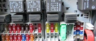
- Poor contact between the ends of the cylindrical fuses and the spring-loaded elements in the mounting block. It arises due to the design features of the unit. Many owners, tired of dealing with the defect, install homemade blocks for knife inserts. Usually a short section from the GAZ-3110 is used, designed for 13 seats. There are self-assembled units designed for fuses and relays.
Photo gallery
The process of installing a new mounting block with blade elements.
Burnt contact of the standard unit
Destruction from local heating is clearly visible
Jumpers on the new block required to reduce the number of insertion locations
Wired unit