January 15, 2015 Lada.Online 2 806 017 315
The relay and fuse box is also called the mounting block or black box. In the event of a car breakdown related to electrical equipment, the fuses and relays are first checked. If a fuse is blown, you must first determine the cause of its blown before replacing it.
Where are the fuses on the Priora?
- The main mounting block of the Priora is closed with a lid and located at the driver’s left foot. To open it, you need to turn three latches 90° and unclip the lid.
- The fuse box is under the hood, which is located near the expansion tank.
- Another mounting block, which is located near the left foot of the front passenger. To gain access to the fuses and relays, unscrew several screws with a Phillips screwdriver.
Below is a description of each fuse and relay block in order.
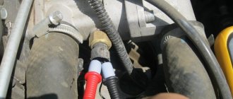
HOW TO REPLACE THE TEMPERATURE SENSOR
Before starting work, you need to partially drain the coolant from the cylinder block.
- Remove the wire.
- Using a 21 wrench, unscrew the temperature sensor.
- Take it off.
- Install the new one in reverse order.
Priora fuse box diagram
| Fuse no. | Current strength, A | "Standard" and "Norm" | “Norma” with air conditioning and “luxury” |
| F1 | 25 | Engine cooling radiator fan | Reserve |
| F2 | 25 | Heated rear window | Mounting block, rear window heating relay (contacts). Electrical package controller, contact “10” of XP2 block. Rear window heating element. |
| F3 | 10 | Right headlight, high beam | Right headlight, high beam lamp. Instrument cluster, headlight high beam indicator. |
| F4 | 10 | Left headlight, high beam | |
| F5 | 10 | Sound signal | Mounting block, horn relay. Sound signal. |
| F6 | 7.5 | Left headlight, low beam | |
| F7 | 7.5 | Right headlight, low beam | |
| F8 | 10 | Alarm signal | Mounting block, alarm relay. Alarm sound. |
| F9 | 25 | Priora heater fuse | Reserve |
| F10 | 7.5/10* | Interior lighting, instrument panels, brake light | Instrument cluster, pin “20”. Brake light switch. Brake light bulbs. Interior lighting unit. Interior lighting. The door sill light on the right front door. Additional brake signal. |
| F11 | 10/20* | Wiper | Mounting block, high speed windshield wiper relay. Switch for cleaners and washers, contact “53a”. Wiper and washer switch, contact “53ah”. Heated rear window switch. Mounting block, rear window heating relay (winding). Windshield wiper motor. Rear window wiper motor (2171,2172). Windshield washer motor. Rear window washer motor (2171,2172). Airbag control unit, pin “25”. |
| F12 | 20/10* | Terminal 15 devices | Instrument cluster, pin “21”. Electrical package controller, contact “9” of block X2. Electromechanical power steering control unit, contact “1” of block X2. Reversing light switch. Reversing lamps. Parking system control unit, contacts “11” and “14”. |
| F13 | 15 | Cigarette lighter fuse Priora | |
| F14 | 5 | Left headlight, parking light, license plate light, trunk light | Side light lamps (left side) Instrument cluster, main light indicator License plate lights Trunk light Electrical package controller, pin “12” of block X2 |
| F15 | 5 | Right headlight, parking light | Side light lamps (right side) Glove compartment lamp |
| F16 | 10 | Terminal 15 ABS | Hydraulic unit, contact "18" |
| F17 | 10 | Left fog lamp | |
| F18 | 10 | Right fog lamp | |
| F19 | 15 | Seat heating | Seat heating switch, contact "1" Front seat heaters |
| F20 | 5/10* | Immobilizer control unit | Recirculation switch (switch on) Mounting block, relay for low beam headlights and parking lights (automatic lighting control system) Heater electric fan relay Automatic lighting control switch Windshield wiper and external lighting control unit, contacts “3”, “11” Automatic climate control system controller installation, pin “1” Automatic window cleaning system sensor (rain sensor), pin “1” |
| F21 | 7.5/5* | Rear fog lights | Light switch, contact "30" Diagnostic block, contact "16" Clock Automatic climate control system controller, contact "14" |
| F22 | -/20* | Reserve | Windshield wiper motor (automatic) Mounting block, windshield wiper relay and windshield wiper high speed relay, (contacts) |
| F23 | -/7.5* | Reserve | Windshield wipers and external lighting control unit, pin “20” |
| F24-F30 | Reserve | ||
| F31 | 30 | Electrical package control unit | Electrical package controller, terminal “2” of block X1 Electrical package controller, terminal “3” of block X1 Driver’s door module, pin “6” Threshold light of the left front door |
| F32 | Reserve | ||
* - for the “Norma” configuration with air conditioning and “luxury”
| Relay | "Norm" | "Norma" with air conditioning | "Lux" |
| K1 | relay for turning on the electric radiator fan of the engine cooling system | Reserve | Relay for turning on the low beam and side lights of the headlights (automatic lighting control system) |
| K2 | rear window heating relay | ||
| K3 | starter activation relay Priora | ||
| K4 | additional relay (ignition relay) | ||
| K5 | space for backup relay | ||
| K6 | windshield washer and wiper relay | ||
| K7 | headlight high beam relay | ||
| K8 | horn relay | ||
| K9 | alarm relay | ||
| K10 | Reserve | Fog light relay | |
| K11 | Reserve | Front seat heating relay | |
| K12 | Reserve | ||
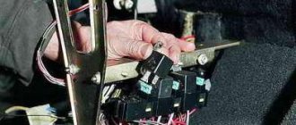
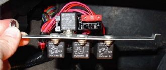
Starter, ignition, rear fog lamp relay
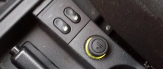
In order to carry out quick checks and repairs, the ignition system relay is installed under the front dashboard of the car, behind the hood release handle. It is located just below the central dashboard. The module is closed with a plastic plug, which must be opened slightly to test for functionality.
Starter, ignition, rear fog lamp relay
Next to the indicated relay, there is a similar one for the rear fog lights and the starter.
The main task of the relay when igniting is to reduce the applied load to the contacts. When the engine starts, the relay turns off some electrical circuits in the vehicle system. The system is used not only in injection, but also in carburetor engines.
In the event of a malfunction or malfunction in the ignition system, it is necessary to monitor the operation of the relay. For this purpose, open the box and carefully remove the desired element. It is attached using contacts to special grooves. The first thing to do is look at the oxidation of the contacts, if necessary, clean them with a soft cloth or treat them with a special liquid.
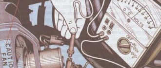
To check functionality, you need to use a regular multimeter. We connect to incoming connections and check the numbers. If there is no short circuit when current is applied, it means the element is not working. Replacement is carried out in a similar manner. It is necessary to use a standard element with the number of amperes indicated on the housing.
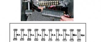
Location of Priora fuses under the hood
- F1 (30 A) – power supply fuse for the electronic engine control system (ECM);
- F2 (60 A) – fuse for the power supply circuit of the engine cooling system fan (power circuit), additional relay (ignition relay), rear window heating, electrical package controller;
- F3 (60 A) – fuse for the power supply circuit of the electric fan of the engine cooling system (relay control circuit), sound signal, alarm signal, ignition switch, instrument cluster, interior lighting, brake light, cigarette lighter;
- F4, F6 (60 A) – generator power circuit fuses;
- F5 (50 A) – fuse for the power supply circuit of the electromechanical power steering
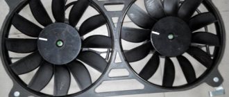
Relay and fuse box for Halla air conditioner
- right electric fan power supply fuse (30 A);
- fuse for the power supply circuit of the left electric fan (30 A).
- right electric fan relay;
- additional relay (sequential activation of left and right electric fans);
- left electric fan relay;
- heater fan power supply fuse (40 A);
- compressor power supply fuse (15 A);
- heater fan relay;
- compressor relay.
Panasonic air conditioner relay and fuse box
- Heater fan maximum speed
- Right fan
- Fan sequential relay (low speed)
- Left fan
- Left fan fuse (low speed)
- Right fan
- Heater fan
- Compressor
- Heater fan
- Compressor
COOLING FAN DIAGNOSTICS
If signals appear on the dashboard indicating that the permissible temperature level in the cooling system has been exceeded, this may indicate that the fan on the VAZ 2114 is not working. The main symptom of the malfunction is that the mechanism does not start even with a significant increase in temperature. It is urgent to turn off the engine to prevent its elements from overheating.
The engine should not be operated with a faulty electric cooling fan. This may damage the cylinder head.
If the cooling fan on a VAZ 2114 does not work, the following malfunctions may be the cause of the breakdown:
- The fan switch sensor on a VAZ 2114 has failed.
- Lack of contact at the sensor connector.
- The wiring has broken.
- Electric fan relay faulty.
- The fuse has blown.
- Damage to the device's electric motor drive.
Unplug the device. Connect it to the battery terminal. Maintaining polarity. If a direct connection to an energy source starts the electric motor, then the drive is working. There may be problems with the wiring, the fuse, or the temperature sensor.
Now it’s time to diagnose the fuse. You don't even have to open the plastic box to do this. If the relay malfunctions, the horn stops working at the same time as the fan. Therefore, if you notice the loss of the sound signal, it means that the fuse has definitely blown. You can find it in the engine compartment in a small plastic box. We release the cover, pressed by two latches, take out the burnt fuse with tweezers and replace it with a new one.
But diagnosing a relay is quite difficult. Especially for those who are exclusively “you” with auto electrics. To check functionality, the easiest way is to find a working relay and temporarily install it. If, after installing a new device, the fan begins to work properly, then it is time to replace the old one.
To diagnose the temperature sensor that supplies a signal to the radiator, you need to disconnect the connector from the sensor and start the ignition. The emergency mode will start, in which the electric fan will start blowing. If the fan starts late when the connector is disconnected, the sensor is most likely faulty. Replacing it will take no more than five minutes. You just need to unscrew two bolts using a Phillips screwdriver and install a new device in its place.
Even if a malfunction has occurred in the VAZ 2114 fan itself, this does not mean that it is time to change it. Sometimes you can simply replace a damaged bearing or brushes. But if the electric motor is faulty, it is much easier to purchase a new mechanism.
Additional mounting block Priora
- F1 (15 A) – main relay and starter interlock circuit fuse;
- F2 (7.5 A) – fuse for the power supply circuit of the ECU (controller);
- F3 (15 A) – Priora fuel pump fuse;
- K1 – main relay;
- K2 is the place where the Priora fuel pump relay is located.
Attention!
The relay and fuse diagram may differ depending on the configuration and production date of the vehicle. Current diagrams of the mounting block are presented in the operating manual for the date of manufacture of the vehicle ().
Let us remind you that on our website you can find detailed instructions for repairing the Lada Priora with your own hands.
Keywords: Lada Priora mounting block | Lada Priora torpedo
8 6 0 2 2 1
Share on social networks:
Protection system
Since the fan is an electrical part, it must have some kind of protection against short circuits or overheating. To provide this protection, it uses a relay and a fuse, which quite often fail, resulting in the fan not working.
Priora cooling fan fuse
To protect the circuit from short circuits and overloads, a fuse is used, which breaks the circuit when it overheats or a short circuit occurs in it.
The Priora uses several fuses to protect the cooling fan circuit: power and control. The cooling fan power fuse is located under the hood in a block near the battery number F3 at 60A. The control circuit fuse is located in the fuse box under the steering column and is numbered F1 at 25A.
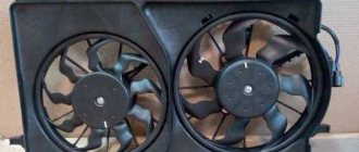
Priora cooling fan relay
The location of the relay depends on the vehicle configuration.
In the “NORM” configuration, the fan relay is located on the main fuse block under the steering column and has the number K1.
In the “NORM+” and “LUX” configurations, the relays are located in the engine compartment and there are 2 of them. For the right fan, relay number 3, for the left fan, relay number 5.
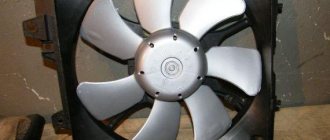
Priora cooling fan sensor
The cooling fan on the Priora turns on automatically when a certain temperature is reached. The coolant temperature is determined by a special sensor installed in the thermostat housing, which sends signals to the ECU when the engine temperature reaches a high temperature, after which the cooling fan turns on and begins to create an artificial air flow through the radiator.
The sensor is a simple part inside which houses a thermistor. As the temperature changes, it changes its resistance.