Engine overheating is an undesirable situation for any car model. Problems with cooling on the VAZ 2114 must be resolved promptly, because An increase in temperature above normal can lead to a breakdown of the gasket under the block head, and then to the appearance of cracks in the block itself. There are several reasons for a sharp increase in engine temperature, but one of them is the failure of the cooling fan. To do the repair yourself, you need to understand what the VAZ 2114 cooling fan diagram (injector) looks like.
Cooling system design features
Depending on the design features, the fan can be turned on in 3 ways:
- using a power sensor for activation of the VSO. This sensor is also called a fan temperature relay, since the power contacts of the electric motor pass directly through the sensor. With this scheme, the load on the thermal relay increases significantly, which reduces its service life;
- using the fan switch sensor, but now closing the contacts in the temperature switch triggers the relay, through which the power contacts of the cooling fan are connected. This connection method is much more reliable than the previous option;
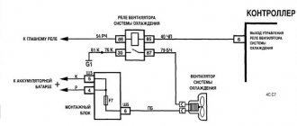
- using an electronic engine control unit. The ECU, focusing on the coolant temperature sensor installed in the engine cooling radiator, supplies power to the VCO through a relay. A resistive temperature sensor is used as a meter. It is this switching circuit that is used on the vast majority of modern cars. On cars equipped with air conditioning, one of the electric fans will be controlled by the comfort unit. This is necessary for forced cooling of the condenser when the interior air conditioning system is activated.
Operating modes
When understanding the operating principle and connection diagram of a radiator fan, you should remember that electric motors often have two speed modes. This is implemented in 2 ways:
- by adding a resistor to the circuit, which increases the resistance and, as a result, reduces the current. The design uses a two-contact sensor, which, depending on the temperature, powers the electric motor directly or through resistors;
- a combination of parallel and series connection. The circuit is used on a car with two fans. They can be connected in series, in which case, according to Ohm's law, they will operate from 6 V, or in series, when 12 V is supplied to each of the VSOs. The modes correspond to low and high speed rotation of the propeller.
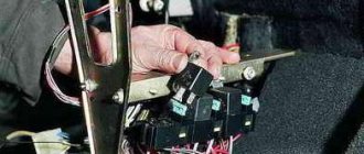
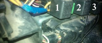
Installing a forced fan button for VAZ 2114
You should start work by disconnecting the ground terminal from the battery so that a short circuit does not occur during the connection of the electrical circuit. The procedure for installing the button is as follows:
- Prepare a block to which the button for forced activation of the VAZ 2114 fan will be connected. To do this, you need to leave 4 terminals with wires on it: two central ones for illuminating the button and two corner ones for controlling the power circuit of the electromagnetic relay.
- Connect two wires with lugs to the electric fan power wires that go to relay K1 (pins 30 and 87). To do this, you need to strip off some of the insulation on the wires approaching the relay and screw the pieces of wire that will go to the relay to them. Ideally, it is better to solder the connection, but you can get by with just a tight twist. The connection points must be carefully insulated.
- Connect the tips of the connected wires to the relay block to pins 30 and 87.
- Connect the control wire from the button block to terminal 85 of the relay, and connect terminal 86 with a wire to the vehicle ground. Install the fan switch button into a free slot on the dashboard, having first removed the plug.
- Install the relay in a convenient place, for example, under the dashboard of a car, and secure it.
- Connect ground to the battery.
- Turn on the ignition and press the fan button. The relay should click and the fan motor should turn on.
This completes the installation of the forced fan button on the VAZ 2114.
Scheme options
Schematic diagram of VSO connection on VAZ 2108, 2109, 21099 (until 1998).
As we can see, the sensor controls the fan relay, which is located in the fuse box. When a certain temperature is reached, the contacts of the temperature switch close, which leads to the flow of current in the electric motor circuit.
Above is a diagram for VAZ 2108, 2109, 21099 cars, but after 1998. As we can see, the power sensor now functions as a relay.
Let's consider a circuit using a resistor to implement two propeller rotation speeds using the VW Passat as an example. The two-position fan power sensor S23, depending on the coolant temperature, closes the contacts directly or through an additional resistance.
Circuit diagram for switching on the cooling fan for a VAZ 2110 carburetor engine.
The circuit diagram for switching on the cooling fan of the VAZ 2110 on carburetor and injection cars is different. On cars with a carburetor engine, a thermobimetallic sensor TM-108 is used for this, and on cars with an injection engine, control is carried out by a controller.
When the fan is controlled by a sensor, the switching temperature depends on the sensor setting temperature, which is indicated on the housing. If the fan does not turn on when the temperature rises to the sensor response temperature, you must first check the serviceability of the sensor. To check, just close the contacts on the sensor and if it turns on, you need to change the sensor. If after closing the terminals the fan does not work, then the cooling fan switching circuit and the integrity of the fuse need to be checked.
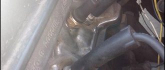
Replacing DVV
To install a new EV switch on sensor, proceed as follows.
- The car is driven into a pit.
- Remove the negative terminal from the battery.
- Unscrew the cap of the expansion tank.
- Place some clean container under the engine.
- After unscrewing the bolt from the engine block, drain the antifreeze into a container.
- Remove the cable plug from the DVV terminals.
- Unscrew the sensor using a 19-mm open-end or socket wrench.
- A new device is installed in its place.
- The EV cable block is secured to the terminals of the new sensor.
- After removing the cap, antifreeze is poured into the radiator neck until the antifreeze level in the expansion tank is between o and “max”.
- Start the engine and monitor the coolant temperature dial indicator. When the arrow approaches the red zone, the fan should turn on.
At the first overheating of the VAZ-2109 engine, you must stop driving and let the engine cool. You need to slowly drive home, watching the coolant temperature gauge along the way. If the DVV breaks down, remove the fan motor cable from the sensor and short-circuit its wires directly. This way, you can return to the garage without letting the antifreeze boil.
How to properly replace the fan switch sensor?
Typical set of tools and accessories for replacement:
- set of heads;
- extension cord with ratchet;
- pliers;
- flat blade screwdriver;
- sealant;
- a socket for removing the sensor or a suitable wrench;
- container for draining liquid (5-6 l);
- coolant for topping up (0.4-0.5 l).
Sequence of steps for replacement:
- Cool the engine to a comfortable temperature.
- Place a container and drain the coolant from the radiator. To access the drain valve, you may need to remove the engine crankcase protection or plastic mud flaps. Some vehicles require removal of the heating system pipe.
- Disconnect the wiring plug from the sensor. Inspect the terminals, clean them from dirt and traces of oxidation. Check the condition of the wires going to the plug. If the insulation becomes cracked or otherwise defective, the worn area must be replaced. Connecting new wires must be carried out in compliance with polarity.
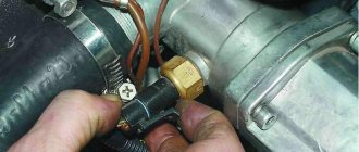
- Unscrew the faulty sensor. It is not recommended to apply a lot of force, as there is a risk of breaking the radiator. To facilitate the process, the use of liquids such as WD40 is allowed. To access the sensor installation location, it may be necessary to remove the battery, its platform, or engine air ducts.
- Lubricate the threads of the new sensor with sealant designed for use in elevated temperatures.
- Install a new O-ring on the sensor. Reusing gaskets is not recommended since the joint is not sealed.
- Screw the sensor into place and tighten to the required torque.
- Install the wiring plug onto the sensor.
- Restore the coolant level in accordance with the vehicle service instructions.
- Warm up the engine to operating temperature and check the operation of the new device. During the first days of operation, carefully monitor the coolant temperature. This applies mainly to domestically produced cars, since the sensors are often defective or set to the wrong response temperature.
On some cars, after turning on the ignition, a new sensor is diagnosed, which consists of turning on the cooling fan for 15-20 seconds (on a cold engine).
How to choose a new sensor?
When purchasing a new sensor, it is recommended to purchase a device of the same type and range as the one you had previously. However, it is possible to replace the device with a similar one, similar in characteristics.
Recommendations for choosing a sensor:
- The operating voltage of the sensor must correspond to the voltage in the on-board network;
- the connection plug must match the wiring harness;
- the sensor must match the current in the circuit. It is unacceptable to use a device designed to operate with a relay in the direct fan connection circuit;
- the temperature range of operation should be close to the marking on the broken device;
- The sensor body must have threads and the length of the threaded part of the appropriate size.
On modern foreign-made cars, the fan switching sensor is selected according to the original spare parts catalogues.
Search form
When the antifreeze in the radiator is heated to a certain temperature, the sensors are different, but, on average, it is 92 degrees, the contacts inside the sensor are closed and voltage is supplied to the fan relay. The light in the room and the fan work in parallel, i.e.
More articles from the Theory section. One is installed at the outlet of the radiator, and the other at the inlet. I take it they duplicate each other?
Yes, and I would like to somehow smooth out the sudden switching on of the radiator fan: There is a solution to the problem, and not even just one!
Let's look at the operation of the radiator fan in more detail: Stories from our readers “Fucking basin!!! Hi all!
The coupling may be blocked by the silicone fluid that is inside it. The circuit is used on a car with two fans. Of course, the dashboard may be lying here and according to the On-Board Computer the readings are completely different.
When the desired change in the contents of the clutch occurs, it will be blocked again and the cooling mechanism will start automatically. The TM sensor only works in conjunction with a relay; the TM, reinforced for high current, can work both with and without a relay. You will laugh, but I work right on the phone. If you want to change your life like me, then this is what I advise you to do right now: 1. When heating the antifreeze in the radiator to a certain temperature, the sensors are different, but, on average, it is 92 degrees, inside the sensor the contacts close and voltage is supplied to the fan relay.
The fan does not turn on.
There will be a large current at relay contacts 87, 30, on the wire from the battery to the fuse and the fan ground, and therefore we must use wires there with a cross-section of at least 2 mm, otherwise the thinner wire will not withstand it and will burn out. To connect, you only need to understand the operating principle of a 4-pin relay and minimal knowledge in installing additional equipment. Messages Yes, and judging by the chips as indicated in the diagram in my primer, it is so. How to make such a system?
Let's look at the operation of the radiator fan in more detail: Stories from our readers “Fucking basin!!! It is purely mechanical, that is, there is no electronics inside. Connection diagram for an electric car radiator cooling fan
Causes of VAZ engine overheating
- A faulty thermostat can cause the engine to overheat. If on a warm engine the upper pipe is hot and the lower pipe is cold, the thermostat is jammed and the antifreeze flows only in a small circle. Or the thermostat will only turn on a large circle, which will not allow the VAZ engine to warm up to the required operating temperature. In this case, the thermostat should be replaced.
- Another reason for excessive engine heating may be airing of the cooling system; in this case, the system must be pressed and air removed from all cavities.
- When the temperature is high, the fan does not turn on - there is a problem with the temperature sensor, the fan relay or the wiring harness to it.
- Sometimes the radiator honeycombs become clogged, which sharply reduces the intensity of heat transfer. It is necessary to thoroughly clean the radiator; it must be done carefully to avoid damage to the cells.
These are the main reasons that affect the quality operation of the VAZ 21093,2109,21099 engine cooling system; with their help, you can identify and eliminate malfunctions, ensuring reliable and durable operation of the engine.
vote
Article rating
Description of DTOZH and DVV
Where is the coolant temperature and fan activation sensor located in 2109 with an injector or carburetor engine, what should I do if the device does not work? First, let's look at the basic questions regarding the purpose, device and principle of operation.
Purpose and functions
The main purpose of the DVV is to activate and deactivate the ventilation device on the engine radiator in order to cool the power unit. The device turns the fan on and off based on the temperature of the liquid in the cooling system. On injection machines, this is DTOZH; turning the fan on and off is controlled by the brain according to the readings of this sensor.
As for the TOZh controller in the VAZ 21093, this device is intended to display readings about the antifreeze temperature on the car’s dashboard in the cabin. With its help, the driver can find out about possible overheating of the power unit.
Location
As for the location, in models 2108, 2109 and 21099 the DTOZH is located between the engine cylinder head and the thermostat, in particular, on the intake hose. The DVV is installed in the threaded hole of the expansion tank with coolant. If you look in the direction of travel of the car, the refrigerant container is installed on the right.
Principle of operation
First, let's look at the operating principle of the antifreeze temperature controller. This device is a thermistor-resistor that operates with a negative coefficient. The amount of resistance in this case can be measured as a result of a decrease or increase in the temperature range. When the car engine heats up, the resistance on the device decreases, and when the power unit cools down, this value increases. For example, when the engine is fully warmed up, the resistance value on the device is 180 Ohms, and at low negative temperatures (-40 degrees) this figure will increase to 100,700 Ohms.
When the driver activates the ignition by turning the key in the lock, the control module (ECU) begins to supply voltage to the controller using a resistor. The DTOZH itself, as mentioned above, is a thermistor; accordingly, the incoming voltage will change in accordance with the temperature of the liquid. When this value decreases, the control module analyzes this, according to which the required volume of fuel for injection into the cylinders is determined. As the car engine warms up, the volume of fuel used for injection will drop.
As for the DVV, it is installed in the negative cable gap, which is connected to the ventilator activation relay in the fuse box. When the temperature value increases to 99 degrees, a short circuit occurs at the controller contacts due to the bimetallic plate. As a result, the current through the device flows to a relay located in the block, from where it is supplied to the electric motor of the device on the fan, ultimately activating the latter (author of the video channel AndRamons).
In “Nines” produced after 1998 and equipped with safety blocks from the VAZ 2114, there is no relay in this section of the circuit. Therefore, the regulator itself is also mounted in the gap of the negative cable, but only the one that is connected directly to the fan. In this case, the closure occurs at a similar temperature. If the antifreeze cools, the plate opens the contacts, causing the electric motor to turn off.
How to check a radiator fan
As we have already established, the radiator fan should turn on when the temperature of the water (antifreeze) exceeds the set value. This can be checked by the instrument readings on the front panel. If the fan does not turn on, then it is necessary to check the entire signal chain.
- Check the presence of supply voltage coming to the product. To do this, you can use a tester or a light bulb. The absence of voltage will indicate a possible blown fuse or poor contact in the wires.
- The serviceability of the fan itself can be checked by applying voltage to it directly from the battery. If it spins, then everything is fine with it, and the defect must be looked for in other devices. If not, and the fan does not spin, then this is the cause of the defect. In principle, you don’t have to stand still and move on, but you must constantly monitor the engine temperature. When the arrow approaches the red sector, you need to stop, open the hood and cool the engine. Two techniques will allow you to move in this case too. Maintain a speed of at least sixty km/h, then the constantly flowing oncoming air will cool the water passing through the radiator, and you will be able to drive as usual as long as you maintain speed. Another technique that allows you to partially replace a non-working fan is to use heating. Turn the stove to maximum heating mode, in this case some of the excess heat will escape through the heater. True, the cabin will be like a bathhouse, but you will be able to get to the nearest service station.
- To check the sensor, you need to disconnect the wires from it and short them together. If the fan turns on and spins, it means that the sensor itself is not working; it cannot be repaired, only replaced. However, if you leave the wires closed, you can move on; with this option, the fan spins constantly, although it is possible that the engine temperature will be lowered, but this is better than standing still.
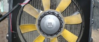
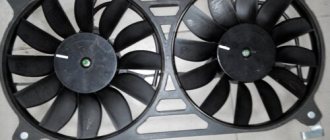
Fan
If the problem lies in the injector or carburetor cooling fan, then you will have to remove it. It is quite possible to repair the unit by replacing the electric motor or impeller.
Diagram with casing, radiator, fan and impeller
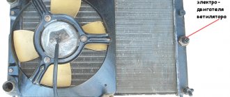
To remove the valve, perform the following operations:
- Disconnect the negative terminal from the battery;
- Disconnect the wire terminals. One of them is mounted on the fan casing;
- Take a wrench and unscrew a couple of connecting bolts. They fix the vent casing on the left tank;
- Next, unscrew another lower nut holding the device casing;
- Now you will need a socket extension to unscrew the right nut on top that secures the vent housing to the radiator;
- All that remains is to unscrew the fan pressure plate. To do this, remove the pair of left nuts;
- Remove the pressure plate by hand;
- Now remove the fan along with the casing.